


 Loading...
Cisco Communication Media Module for Catalyst 6500 Series Switch and Cisco 7600 Series Router Installation and Verification Note
Product Number: WS-SVC-CMM
Last Updated: March 23, 2009
This publication contains the procedures for installing and configuring the Catalyst 6500 series switch and Cisco 7600 series router Communication Media Module (CMM). Installation and configuration procedures are provided for the following CMM port adapters:
•6-port T1 port adapter (WS-SVC-CMM-6T1)
•6-port E1 port adapter (WS-SVC-CMM-6E1)
•24-port FXS port adapter (WS-SVC-CMM-24FXS)
•128-port ad-hoc conferencing and transcoding (ACT) port adapter (WS-SVC-CMM-ACT)
Note Except where specifically differentiated, the term “Catalyst 6500 series switches” includes both the Catalyst 6500 series switches and the Catalyst 6000 series switches.
Note Throughout this publication, except where specifically differentiated, the term supervisor engine refers to Supervisor Engine 1, Supervisor Engine 2, Supervisor Engine 720, and the Supervisor Engine 32. Additionally, the term Multilayer Switch Feature Card (MSFC) refers to MSFC, MSFC2, and MSFC3.
Americas Headquarters:
Cisco Systems, Inc., 170 West Tasman Drive, San Jose, CA 95134-1706 USA

Contents
Contents
This publication contains these sections:
•Front Panel Descriptions, page 2
•Requirements, page 6
•Safety Overview, page 7
•Required Tools, page 10
•Installing and Removing the Module, page 10
•Removing and Replacing Port Adapters, page 19
•Verifying the Installation, page 25
•RJ-45 Port Connector and Cabling Specifications, page 25
•RJ-21 Port Connector and Cabling Specifications, page 27
•Accessing the Port Adapter Ports, page 28
•Configuring the Port Adapter Ports, page 29
•Configuring the Port Adapter Clock Source, page 29
•Disaster Recovery for Module Software Upgrades, page 30
•Password Recovery, page 32
•Regulatory Standards Compliance, page 33
•Related Documentation, page 33
•Obtaining Documentation, Obtaining Support, and Security Guidelines, page 33
Front Panel Descriptions
These sections describe the front panel features of the module and the port adapters:
•CMM Module, page 2
•6-Port T1 and E1 Port Adapters, page 4
•24-Port FXS Port Adapter, page 5
•Ad-Hoc Conferencing and Transcoding Port Adapter, page 6
CMM Module
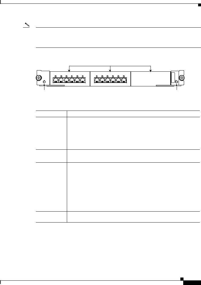
The front panel features of the modules are as follows:
•STATUS LED—When the module powers up, it initializes various hardware components and communicates with the supervisor engine. The STATUS LED shows the dialog with the supervisor engine and the results of the initialization. During the normal initialization sequence, the STATUS LED changes from off to red, to orange, and then to green. Table 1 describes the STATUS LED operation.
•Port adapter slots—Figure 1 and Figure 2 show the E1 port adapter in the left and middle slots, with a blank filler plate in the right slot.
•REAR MODULE STATUS LED—Table 2 describes the REAR MODULE STATUS LED operation.
Cisco Communication Media Module for Catalyst 6500 Series Switch and Cisco 7600 Series Router Installation and Verification Note
2
Front Panel Descriptions
Note For information on the supervisor engine LEDs, see the Catalyst 6500 Series Switch Supervisor Engine Guide at this URL: http://www.cisco.com/en/US/docs/switches/lan/catalyst6500/hardware/Module_Installation/Sup_Eng_ Guide/supe_gd.html
Figure 1 |
|
CMM Front Panel Features |
|
|
|
|
|||||
|
|
|
|
|
|
Interface Module slots |
|||||
WS-SVC-CMM |
|
|
|
|
|
WS-SVC-CMM-6E1 |
|
|
|
|
|
WS-SVC-CMM-6E1 |
|
|
|
|
|
|
|
|
|
|
|
0 |
1 |
2 |
3 |
4 |
5 |
0 |
1 |
2 |
3 |
4 |
5 |
STATUS |
|
|
|
|
|
|
|
|
|
|
|
Communication Media Module 6-Port E1 Interface Port Adapter. |
|
|
|
6-Port E1 Interface Port Adapter. |
|
|
|
|
|||
|
MDL |
STATUS |
|
REAR |
|
68447
STATUS LED |
REAR MODULE STATUS LED |
Table 1 |
Module STATUS LED |
Color
Off
Red
Orange
Green
Description
•The module is waiting for the supervisor engine to provide power.
•The module is not online.
•The module is not receiving power, which could be caused by the following:
–Power is not available to the module.
–Module temperature is over the limit1.
•The module is released from reset by the supervisor engine and is booting.
•If the boot code fails to execute, the LED stays red after power up.
•The module is initializing hardware or communicating with the supervisor engine.
•A fault occurred during the initialization sequence.
•If the module fails to download its Field Programmable Gate Arrays (FPGAs) on startup, it continues initializing and is granted module online status from the supervisor engine, but the LED stays orange.
•If the module is not granted module online status from the supervisor engine, the LED stays orange. This problem could be caused by the supervisor engine detecting a failure in an external loopback test that it issued to the module.
•The module is operational; the supervisor engine has granted module online status.
1.Enter the show environment temperature mod command to display the temperature of each of the four sensors on the module.
Cisco Communication Media Module for Catalyst 6500 Series Switch and Cisco 7600 Series Router Installation and Verification Note
3

Front Panel Descriptions
Table 2 |
Rear Module STATUS LED |
|
|
|
|
Color |
|
Description |
|
|
|
Green |
|
Port adapter in slot 4 is up and operational. |
|
|
|
Red |
|
Port adapter in slot 4 is shut down. |
|
|
|
No light |
|
Slot 4 port adapter is not located by the system. |
|
|
|
6-Port T1 and E1 Port Adapters
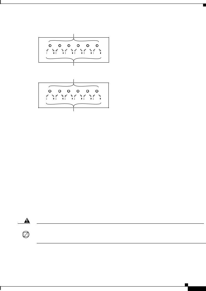
The front panel features of the 6-port T1 and E1 port adapters are as follows:
•Receive port LEDs—The LEDs on the front panel indicate the status of each T1 and E1 interface. Table 3 describes the receive port LED operation.
•RJ-45 connectors—See the “RJ-45 Port Connector and Cabling Specifications” section on page 25 for details.
Figure 2 shows the front panels of the 6-port T1 and E1 port adapters.
Cisco Communication Media Module for Catalyst 6500 Series Switch and Cisco 7600 Series Router Installation and Verification Note
4
Front Panel Descriptions
Figure 2 |
6-Port T1 and E1 Port Adapter Front Panel Features |
Receive port LEDs
WS-SVC-CMM-6T1
0 |
|
1 |
|
|
|
2 |
|
|
|
3 |
|
|
|
4 |
|
|
|
5 |
|
|
|
|
|||||||||||||||||||||||||||
|
|
|
|
|
|
|
|
|
|
|
|
|
|
|
|
|
|
|
|
|
|
|
|
|
|
|
|
|
|
|
|
|
|
|
|
|
|
|
|
|
|
|
|
|
|
|
|
|
|
|
|
|
|
|
|
|
|
|
|
|
|
|
|
|
|
|
|
|
|
|
|
|
|
|
|
|
|
|
|
|
|
|
|
|
|
|
|
|
|
|
|
|
|
|
|
|
|
|
|
|
|
|
|
|
|
|
|
|
|
|
|
|
|
|
|
|
|
|
|
|
|
|
|
|
|
|
|
|
|
|
|
|
|
|
|
|
|
|
|
|
|
|
|
|
|
|
|
|
|
|
|
|
|
|
|
|
|
|
|
|
|
|
|
|
|
|
|
|
|
|
|
|
|
|
|
|
|
|
|
|
|
|
|
|
|
|
|
|
|
|
|
|
|
|
|
|
|
|
|
|
|
|
|
|
|
|
|
|
|
|
|
|
|
|
|
|
|
|
|
|
|
|
|
|
|
|
|
|
|
|
|
|
|
|
|
|
|
|
|
|
|
|
|
|
|
|
|
|
|
|
|
|
|
|
|
|
|
|
|
|
|
|
|
|
|
|
|
|
|
|
|
|
|
|
|
|
|
|
|
|
|
|
|
|
|
|
|
|
|
|
|
|
|
|
|
|
|
|
|
6-Port T1 Interface Port Adapter
68448
RJ-45 connectors
Receive port LEDs
WS-SVC-CMM-6E1
0 |
|
1 |
|
|
|
2 |
|
|
|
3 |
|
|
|
4 |
|
|
|
5 |
|
|
|
|
||||||||||||||||||||||||||
|
|
|
|
|
|
|
|
|
|
|
|
|
|
|
|
|
|
|
|
|
|
|
|
|
|
|
|
|
|
|
|
|
|
|
|
|
|
|
|
|
|
|
|
|
|
|
|
|
|
|
|
|
|
|
|
|
|
|
|
|
|
|
|
|
|
|
|
|
|
|
|
|
|
|
|
|
|
|
|
|
|
|
|
|
|
|
|
|
|
|
|
|
|
|
|
|
|
|
|
|
|
|
|
|
|
|
|
|
|
|
|
|
|
|
|
|
|
|
|
|
|
|
|
|
|
|
|
|
|
|
|
|
|
|
|
|
|
|
|
|
|
|
|
|
|
|
|
|
|
|
|
|
|
|
|
|
|
|
|
|
|
|
|
|
|
|
|
|
|
|
|
|
|
|
|
|
|
|
|
|
|
|
|
|
|
|
|
|
|
|
|
|
|
|
|
6-Port E1 Interface Port Adapter
RJ-45 connectors
68449
Table 3 |
6-Port T1 and E1 Port Adapters Receive Port LEDs |
|
|
|
|
Color |
|
Description |
|
|
|
Green |
|
T1/E1 interface is operational. |
|
|
|
Red |
|
T1/E1 receive alarm. |
|
|
|
Yellow |
|
T1/E1 remote alarm. |
|
|
|
Off |
|
T1/E1 interface has been administratively shut down, or there is no |
|
|
power. |
|
|
|
24-Port FXS Port Adapter
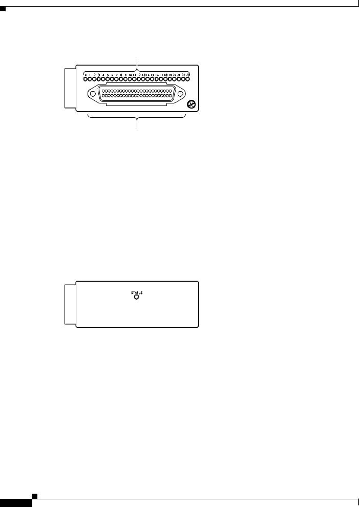
The front panel features of the 24-port FXS port adapter are as follows:
•Receive port LEDs—The LEDs on the front panel indicate the status of each FXS interface. Table 4 describes the receive port LED operation.
•RJ-21 connector—See the “RJ-21 Port Connector and Cabling Specifications” section on page 27 for details.
Warning If the symbol of suitability with an overlaid cross appears above a port, you must not connect the port to a public network that follows the European Union standards. Connecting the port to this type  of public network can cause severe personal injury or can damage the unit. Statement 1031
Figure 3 shows the front panel of the 24-port FXS port adapter.
Cisco Communication Media Module for Catalyst 6500 Series Switch and Cisco 7600 Series Router Installation and Verification Note
5
Requirements
Figure 3 |
24-Port FXS Port Adapter Front Panel Features |
Receive port LEDs
WS-SVC-CMM-24FXS
FXS Interface Board Adapter
98289
|
RJ-21 connector |
|
Table 4 |
24-Port FXS Port Adapter Receive Port LEDs |
|
|
|
|
Color |
|
Description |
|
|
|
Green |
|
Port is off-hook or ringing. |
|
|
|
Off |
|
Port is not active (connected device on-hook) or is disabled through |
|
|
the CLI. |
|
|
|
Ad-Hoc Conferencing and Transcoding Port Adapter
The front panel features of the ad-hoc conferencing and transcoding port adapter are shown in Figure 4, and the STATUS LED is described in Table 5.
Figure 4 |
Ad-Hoc Conferencing and Transcoding Port Adapter Front Panel Features |
||
|
|
WS-SVC-CMM-ACT |
|
|
|
|
|
Ad-hoc Conferencing and Transcoding Port Adapter
99302
Table 5 |
Ad-Hoc Conferencing and Transcoding Port Adapter STATUS LED |
|
|
|
|
Color |
|
Description |
|
|
|
Green |
|
Port adapter is up and operational. |
|
|
|
Red |
|
Port adapter is shut down. |
|
|
|
Off |
|
Port adapter is not located by the system. |
|
|
|
Requirements
These sections describe the hardware and software requirements:
•Hardware Requirements, page 7
•Software Requirements, page 7
Cisco Communication Media Module for Catalyst 6500 Series Switch and Cisco 7600 Series Router Installation and Verification Note
6

Safety Overview
Hardware Requirements
The hardware requirements for the modules are as follows:
•Catalyst 6500 series switch.
•Cisco 7600 series router.
•252.0 Watts (6.00 A @ 42 V) of available system power
•A Supervisor Engine 2, Supervisor Engine 720, or Supervisor Engine 32—The supervisor engine can have an MSFC, MSFC2, or MSFC3, but the CMM does not require one for configuration or operation.
•Supervisor Engine 32—The minimum version for the CMM is 12.4(3) and the recommended version is 12.4(7a). The minimum version for the Supervisor Engine 32 is 12.2(18)SXF4 and the recommended version is 12.2(18)SXF4.
•Port adapters—You can install up to three T1, E1, or FXS port adapters into slots 1 through 3 on either base module.
You can install up to four ACT port adapters into either base module. (The internally located slot 4 is reserved for the ACT port adapter.)
Note You cannot mix T1 port adapters with E1 port adapters, but any other combination of port adapters is supported.
•Module blank filler plate (WS-SVC-CMM-BLANK) for unused port adapter slots.
Software Requirements
For software requirements, see the Release Notes for the Cisco Catalyst 6500 Series and the Cisco 7600 Series Communication Media Module at this URL:
http://www.cisco.com/en/US/products/hw/switches/ps708/prod_release_notes_list.html
Safety Overview
Throughout this publication, safety warnings appear in procedures that, if performed incorrectly, can harm you. A warning symbol precedes each warning statement.
Warning IMPORTANT SAFETY INSTRUCTIONS
This warning symbol means danger. You are in a situation that could cause bodily injury. Before you work on any equipment, be aware of the hazards involved with electrical circuitry and be familiar with standard practices for preventing accidents. Use the statement number provided at the end of each warning to locate its translation in the translated safety warnings that accompanied this device. Statement 1071
SAVE THESE INSTRUCTIONS
Cisco Communication Media Module for Catalyst 6500 Series Switch and Cisco 7600 Series Router Installation and Verification Note
7

Safety Overview
Warning Ultimate disposal of this product should be handled according to all national laws and regulations.
Statement 1040
Warning Only trained and qualified personnel should be allowed to install, replace, or service this equipment.
Statement 1030
Warning If the symbol of suitability with an overlaid cross appears above a port, you must not connect the port to a public network that follows the European Union standards. Connecting the port to this type  of public network can cause severe personal injury or can damage the unit. Statement 1031
Warning During this procedure, wear grounding wrist straps to avoid ESD damage to the card. Do not directly touch the backplane with your hand or any metal tool, or you could shock yourself. Statement 94
Warning Invisible laser radiation may be emitted from disconnected fibers or connectors. Do not stare into beams or view directly with optical instruments. Statement 1051
Warning Blank faceplates and cover panels serve three important functions: they prevent exposure to hazardous voltages and currents inside the chassis; they contain electromagnetic interference (EMI) that might disrupt other equipment; and they direct the flow of cooling air through the chassis. Do not operate the system unless all cards, faceplates, front covers, and rear covers are in place.
Statement 1029
Warning Hazardous voltage or energy is present on the backplane when the system is operating. Use caution when servicing. Statement 1034
Warning Before opening the unit, disconnect the telephone-network cables to avoid contact with telephone-network voltages. Statement 1041
Warning Do not work on the system or connect or disconnect cables during periods of lightning activity.
Statement 1001
Warning Never install telephone jacks in wet locations unless the jack is specifically designed for wet locations. Statement 1036
Cisco Communication Media Module for Catalyst 6500 Series Switch and Cisco 7600 Series Router Installation and Verification Note
8

Safety Overview
Warning Never touch uninsulated telephone wires or terminals unless the telephone line has been disconnected at the network interface. Statement 1037
Warning Hazardous network voltages are present in WAN ports regardless of whether power to the unit is OFF or ON. To avoid electric shock, use caution when working near WAN ports. When detaching cables, detach the end away from the unit first. Statement 1026
Warning To avoid electric shock, do not connect safety extra-low voltage (SELV) circuits to telephone-network voltage (TNV) circuits. LAN ports contain SELV circuits, and WAN ports contain TNV circuits. Some LAN and WAN ports both use RJ-45 connectors. Use caution when connecting cables. Statement 1021
Warning To reduce the risk of fire, use only No. 26 AWG or larger telecommunication line cord. Statement 1023
Cisco Communication Media Module for Catalyst 6500 Series Switch and Cisco 7600 Series Router Installation and Verification Note
9

Required Tools
Required Tools
Warning Only trained and qualified personnel should be allowed to install, replace, or service this equipment.
Statement 1030
These tools are required to remove and replace the module and port adapters:
•Flat-blade screwdriver (for the module)
•Number 1 Phillips screwdriver (for the screws and standoffs)
•Antistatic mat or foam pad
•Your own ESD-prevention equipment or the disposable grounding wrist strap that is included with all upgrade kits, field-replaceable units (FRUs), and spares
Whenever you handle a module, always use a wrist strap or other grounding device to prevent electrostatic discharge (ESD). For information on preventing ESD, see the “Preventing ESD” section of the Regulatory Compliance and Safety Information publication.
Installing and Removing the Module
This section describes the procedures for installing and removing the module:
•Installing the Module, page 10
•Removing the Module, page 17
Installing the Module
This section describes how to install the module into the Catalyst 6500 series switch or the Cisco 7600 series router.
Note All modules, including the supervisor engine (if you have redundant supervisor engines), support hot swapping. You can add, replace, or remove modules without interrupting the system power or causing other software or interfaces to shut down. For more information about hot-swapping modules, see the
Catalyst 6500 Series Switch Module Installation Guide.
Warning During this procedure, wear grounding wrist straps to avoid ESD damage to the card. Do not directly touch the backplane with your hand or any metal tool, or you could shock yourself. Statement 94
To install the module into the Catalyst 6500 series switch or the Cisco 7600 series router, perform these steps:
Step 1 Make sure that you take the necessary precautions to prevent ESD damage.
Step 2 Choose a slot for the module.
Cisco Communication Media Module for Catalyst 6500 Series Switch and Cisco 7600 Series Router Installation and Verification Note
10
Installing and Removing the Module
Step 3 Verify that there is enough clearance to accommodate any interface equipment that you will connect directly to the module ports. If possible, place modules between empty slots that contain only module filler plates.
Step 4 Verify that the captive installation screws are tightened on all modules that are installed in the chassis.
This action ensures that the EMI gaskets on all modules are fully compressed to maximize the opening space for the replacement module.
Note If the captive installation screws are loose, the EMI gaskets on the installed modules will push adjacent modules toward the open slot, reducing the opening size and making it difficult to install the replacement module.
Step 5 Remove the module filler plate by removing the two Phillips pan-head screws from the filler plate. (To remove a module, see the “Removing the Module” section on page 17.)
Step 6 Fully open both ejector levers on the new or replacement module. (See Figure 5.)
Step 7 Depending on the orientation of the slots in the chassis (horizontal or vertical), perform one of the following sets of substeps:
Horizontal slots
a.Position the module in the slot. Make sure that you align the sides of the module carrier with the slot guides on each side of the slot. (See Figure 5.)
a.Carefully slide the module into the slot until the EMI gasket along the top edge of the module makes contact with the module in the slot above it and both ejector levers have closed to approximately 45 degrees with respect to the module faceplate. (See Figure 6.)
Cisco Communication Media Module for Catalyst 6500 Series Switch and Cisco 7600 Series Router Installation and Verification Note
11
Loading...