


 Loading...
Supervisor Engine 720 Switch Processor and Route Processor Memory Installation Note
Product Number: MEM-S2-512MB=, MEM-MSFC2-512MB=, MEM-S3-1GB=,
MEM-MSFC3-1GB=
This publication describes how to upgrade the dynamic random-access memory (DRAM) dual inline memory modules (DIMMs) on the Supervisor Engine 720.
Contents
This publication consists of these sections:
•Safety Overview, page 2
•Installing the SP and RP Memory Upgrade Kit, page 8
•Translated Safety Warnings, page 20
•Obtaining Documentation, page 27
•Documentation Feedback, page 28
•Cisco Product Security Overview, page 28
•Obtaining Technical Assistance, page 29
•Obtaining Additional Publications and Information, page 31
Note For translations of the warnings in this publication, see the “Translated Safety Warnings” section on page 20.
Corporate Headquarters:
Cisco Systems, Inc., 170 West Tasman Drive, San Jose, CA 95134-1706 USA
© 2003–2005 Cisco Systems, Inc. All rights reserved.

Safety Overview
Safety Overview
Safety warnings appear throughout this publication in procedures that may harm you if performed incorrectly. A warning symbol precedes each warning statement.
Warning IMPORTANT SAFETY INSTRUCTIONS
This warning symbol means danger. You are in a situation that could cause bodily injury. Before you work on any equipment, be aware of the hazards involved with electrical circuitry and be familiar with standard practices for preventing accidents. Use the statement number provided at the end of each warning to locate its translation in the translated safety warnings that accompanied this device. Statement 1071
SAVE THESE INSTRUCTIONS
Waarschuwing BELANGRIJKE VEILIGHEIDSINSTRUCTIES
Dit waarschuwingssymbool betekent gevaar. U verkeert in een situatie die lichamelijk letsel kan veroorzaken. Voordat u aan enige apparatuur gaat werken, dient u zich bewust te zijn van de bij elektrische schakelingen betrokken risico's en dient u op de hoogte te zijn van de standaard praktijken om ongelukken te voorkomen. Gebruik het nummer van de verklaring onderaan de waarschuwing als u een vertaling van de waarschuwing die bij het apparaat wordt geleverd, wilt raadplegen.
BEWAAR DEZE INSTRUCTIES
Varoitus TÄRKEITÄ TURVALLISUUSOHJEITA
Tämä varoitusmerkki merkitsee vaaraa. Tilanne voi aiheuttaa ruumiillisia vammoja. Ennen kuin käsittelet laitteistoa, huomioi sähköpiirien käsittelemiseen liittyvät riskit ja tutustu onnettomuuksien yleisiin ehkäisytapoihin. Turvallisuusvaroitusten käännökset löytyvät laitteen mukana toimitettujen käännettyjen turvallisuusvaroitusten joukosta varoitusten lopussa näkyvien lausuntonumeroiden avulla.
SÄILYTÄ NÄMÄ OHJEET
Attention IMPORTANTES INFORMATIONS DE SÉCURITÉ
Ce symbole d'avertissement indique un danger. Vous vous trouvez dans une situation pouvant entraîner des blessures ou des dommages corporels. Avant de travailler sur un équipement, soyez conscient des dangers liés aux circuits électriques et familiarisez-vous avec les procédures couramment utilisées pour éviter les accidents. Pour prendre connaissance des traductions des avertissements figurant dans les consignes de sécurité traduites qui accompagnent cet appareil, référez-vous au numéro de l'instruction situé à la fin de chaque avertissement.
CONSERVEZ CES INFORMATIONS
Supervisor Engine 720 Switch Processor and Route Processor Memory Installation Note
2 |
78-15538-02 |
|
|

Safety Overview
Warnung WICHTIGE SICHERHEITSHINWEISE
Dieses Warnsymbol bedeutet Gefahr. Sie befinden sich in einer Situation, die zu Verletzungen führen kann. Machen Sie sich vor der Arbeit mit Geräten mit den Gefahren elektrischer Schaltungen und den üblichen Verfahren zur Vorbeugung vor Unfällen vertraut. Suchen Sie mit der am Ende jeder Warnung angegebenen Anweisungsnummer nach der jeweiligen Übersetzung in den übersetzten Sicherheitshinweisen, die zusammen mit diesem Gerät ausgeliefert wurden.
BEWAHREN SIE DIESE HINWEISE GUT AUF.
Avvertenza IMPORTANTI ISTRUZIONI SULLA SICUREZZA
Questo simbolo di avvertenza indica un pericolo. La situazione potrebbe causare infortuni alle persone. Prima di intervenire su qualsiasi apparecchiatura, occorre essere al corrente dei pericoli relativi ai circuiti elettrici e conoscere le procedure standard per la prevenzione di incidenti. Utilizzare il numero di istruzione presente alla fine di ciascuna avvertenza per individuare le traduzioni delle avvertenze riportate in questo documento.
CONSERVARE QUESTE ISTRUZIONI
Advarsel VIKTIGE SIKKERHETSINSTRUKSJONER
Dette advarselssymbolet betyr fare. Du er i en situasjon som kan føre til skade på person. Før du begynner å arbeide med noe av utstyret, må du være oppmerksom på farene forbundet med elektriske kretser, og kjenne til standardprosedyrer for å forhindre ulykker. Bruk nummeret i slutten av hver advarsel for å finne oversettelsen i de oversatte sikkerhetsadvarslene som fulgte med denne enheten.
TA VARE PÅ DISSE INSTRUKSJONENE
Aviso INSTRUÇÕES IMPORTANTES DE SEGURANÇA
Este símbolo de aviso significa perigo. Você está em uma situação que poderá ser causadora de lesões corporais. Antes de iniciar a utilização de qualquer equipamento, tenha conhecimento dos perigos envolvidos no manuseio de circuitos elétricos e familiarize-se com as práticas habituais de prevenção de acidentes. Utilize o número da instrução fornecido ao final de cada aviso para localizar sua tradução nos avisos de segurança traduzidos que acompanham este dispositivo.
GUARDE ESTAS INSTRUÇÕES
¡Advertencia! INSTRUCCIONES IMPORTANTES DE SEGURIDAD
Este símbolo de aviso indica peligro. Existe riesgo para su integridad física. Antes de manipular cualquier equipo, considere los riesgos de la corriente eléctrica y familiarícese con los procedimientos estándar de prevención de accidentes. Al final de cada advertencia encontrará el número que le ayudará a encontrar el texto traducido en el apartado de traducciones que acompaña a este dispositivo.
GUARDE ESTAS INSTRUCCIONES
Supervisor Engine 720 Switch Processor and Route Processor Memory Installation Note
|
78-15538-02 |
3 |
|
|
|

Safety Overview
Varning! VIKTIGA SÄKERHETSANVISNINGAR
Denna varningssignal signalerar fara. Du befinner dig i en situation som kan leda till personskada. Innan du utför arbete på någon utrustning måste du vara medveten om farorna med elkretsar och känna till vanliga förfaranden för att förebygga olyckor. Använd det nummer som finns i slutet av varje varning för att hitta dess översättning i de översatta säkerhetsvarningar som medföljer denna anordning.
SPARA DESSA ANVISNINGAR
Supervisor Engine 720 Switch Processor and Route Processor Memory Installation Note
4 |
78-15538-02 |
|
|
Safety Overview
Aviso INSTRUÇÕES IMPORTANTES DE SEGURANÇA
Este símbolo de aviso significa perigo. Você se encontra em uma situação em que há risco de lesões corporais. Antes de trabalhar com qualquer equipamento, esteja ciente dos riscos que envolvem os circuitos elétricos e familiarize-se com as práticas padrão de prevenção de acidentes. Use o número da declaração fornecido ao final de cada aviso para localizar sua tradução nos avisos de segurança traduzidos que acompanham o dispositivo.
GUARDE ESTAS INSTRUÇÕES
Advarsel VIGTIGE SIKKERHEDSANVISNINGER
Dette advarselssymbol betyder fare. Du befinder dig i en situation med risiko for legemesbeskadigelse. Før du begynder arbejde på udstyr, skal du være opmærksom på de involverede risici, der er ved elektriske kredsløb, og du skal sætte dig ind i standardprocedurer til undgåelse af ulykker. Brug erklæringsnummeret efter hver advarsel for at finde oversættelsen i de oversatte advarsler, der fulgte med denne enhed.
GEM DISSE ANVISNINGER
Supervisor Engine 720 Switch Processor and Route Processor Memory Installation Note
|
78-15538-02 |
5 |
|
|
|
Safety Overview
Supervisor Engine 720 Switch Processor and Route Processor Memory Installation Note
6 |
78-15538-02 |
|
|
Safety Overview
Supervisor Engine 720 Switch Processor and Route Processor Memory Installation Note
|
78-15538-02 |
7 |
|
|
|
Installing the SP and RP Memory Upgrade Kit
Installing the SP and RP Memory Upgrade Kit
This section is divided into the following topics:
•Required Tools, page 8
•Removing the Supervisor Engine 720, page 8
•Removing and Installing the DRAM DIMMs, page 11
•Installing the Supervisor Engine 720, page 14
Warning Only trained and qualified personnel should be allowed to install, replace, or service this equipment.
Statement 1030
Required Tools
The following tools are required to perform the memory upgrade kit installation:
•Antistatic mat or foam pad to support and protect the removed supervisor engine
•3/16-inch flat-blade screwdriver for the captive installation screws on the supervisor engine
•Your own ESD-prevention equipment or the disposable grounding wrist strap included with all upgrade kits, field-replaceable units (FRUs), and spares
Caution Always use an ESD wrist strap when handling modules or coming into contact with internal components.
Warning Blank faceplates and cover panels serve three important functions: they prevent exposure to hazardous voltages and currents inside the chassis; they contain electromagnetic interference (EMI) that might disrupt other equipment; and they direct the flow of cooling air through the chassis. Do not operate the system unless all cards, faceplates, front covers, and rear covers are in place. Statement 1029
Warning Hazardous voltage or energy is present on the backplane when the system is operating. Use caution when servicing. Statement 1034
Removing the Supervisor Engine 720
To install the DRAM DIMM upgrade, you must first remove the Supervisor Engine 720 from the switch.
The Supervisor Engine 720 is a required system component. If only one Supervisor Engine 720 is present, removing it while the system is operating causes the system to halt. When two Supervisor Engine 720s are installed, hot swapping allows you to remove and replace one of the supervisor engines without turning off the system power.
To avoid erroneous failure messages, note the current configuration of all interfaces before you remove or replace another switching module, and allow at least 15 seconds for the system to reinitialize after a module has been removed or replaced.
Supervisor Engine 720 Switch Processor and Route Processor Memory Installation Note
8 |
78-15538-02 |
|
|
Installing the SP and RP Memory Upgrade Kit
Caution Always use an ESD wrist strap when handling the Supervisor Engine 720 or coming in contact with internal components.
To remove the supervisor engine, follow these steps:
Step 1 Disconnect any network interface cables attached to the supervisor engine.
Step 2 Verify that the captive installation screws on all of the modules in the chassis are tight. This step ensures that the space created by the removed module is maintained.
Note If the captive installation screws are loose, the EMI gaskets on the installed modules will push the modules toward the open slot, reducing the opening size and making it difficult to reinstall the module.
Step 3 Loosen the two captive screws on the supervisor engine that is to be removed.
Step 4 Depending on the orientation of the slots in the chassis (horizontal or vertical), perform one of the following two sets of steps:
Horizontal slots
a.Place your thumbs on the left and right ejector levers, and simultaneously rotate the levers outward to unseat the supervisor engine from the backplane connector. (See Figure 1.)
b.Grasp the front edge of the supervisor engine, and slide the supervisor engine partially out of the slot. Place your other hand under the supervisor engine to support the weight of the module. Do not touch the module circuitry. (See Figure 2.)
Vertical slots
a.Place your thumbs on the ejector levers located at the top and bottom of the supervisor engine, and simultaneously rotate the levers outward to unseat the supervisor engine from the backplane connector.
b.Grasp the edges of the supervisor engine, and slide the supervisor engine straight out of the slot. Do not touch the module circuitry.
Step 5 Place the supervisor engine on an antistatic mat or antistatic foam.
Supervisor Engine 720 Switch Processor and Route Processor Memory Installation Note
|
78-15538-02 |
9 |
|
|
|
Installing the SP and RP Memory Upgrade Kit
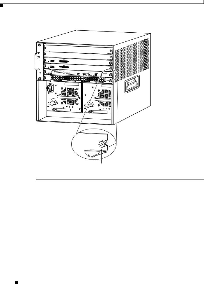
Figure 1 |
Opening the Ejector Levers (Horizontal Chassis Shown) |
1
2
3
4
5
WS-X6348-RJ-45V
6
48 PORT |
|
10/100 BASE-T |
ETHERNET SWITCHING |
|
MODULE |
o |
|
o |
|
|
|
INPUT |
FAN |
OUTPUT |
OK |
OK |
FAIL |
INPUT |
FAN |
OUTPUT |
OK |
OK |
FAIL |
91525
Ejector lever 
Captive installation screw
Supervisor Engine 720 Switch Processor and Route Processor Memory Installation Note
10 |
78-15538-02 |
|
|
Loading...