


SPA8000
Table of contents
 Loading...
Cisco Small Business Pro
SPA2102, SPA3102, SPA8000, PAP2T, WRP400
Analog Telephone Adapters
ADMINISTRATION
GUIDE

6bZg^XVh=ZVYfjVgiZgh
8^hXdHnhiZbh!>cX#
HVc?dhZ!86
6h^VEVX^[^X=ZVYfjVgiZgh
8^hXdHnhiZbhJH6EiZ#AiY#
H^c\VedgZ
:jgdeZ=ZVYfjVgiZgh
8^hXdHnhiZbh>ciZgcVi^dcVa7K
6bhiZgYVb!I]ZCZi]ZgaVcYh
8^hXd]VhbdgZi]Vc '%%d[[^XZhldgaYl^YZ#6YYgZhhZh!e]dcZcjbWZgh!VcY [VmcjbWZghVgZa^hiZYdci]Z8^hXdLZWh^iZVilll#X^hXd#Xdb$\d$d[[^XZh#
889:!88:CI!8^hXd:dh!8^hXdAjb^c!8^hXdCZmjh!8^hXdHiVY^jbK^h^dc!8^hXdIZaZEgZhZcXZ!8^hXdLZW:m!i]Z8^hXdad\d!98:!VcYLZaXdbZidi]Z=jbVcCZildg`VgZigVYZbVg`h08]Vc\^c\i]ZLVnLZLdg`!
A^kZ!EaVn!VcYAZVgcVcY8^hXdHidgZVgZhZgk^XZbVg`h0VcY6XX ZhhGZ\^higVg!6^gdcZi!6hncXDH!7g^c\^c\i]ZBZZi^c\IdNdj!8ViVanhi!8896!889E!88>:!88>E!88C6!88CE!88HE!88KE!8^hXd!i]Z8^hXd8Zgi^[^ZY
>ciZgcZildg`:meZgiad\d!8^hXd>DH!8^hXdEgZhh!8^hXdHnhiZbh!8^hXdHnhiZbh8Ve^iVa!i]Z8^hXdHnhiZbhad\d!8^hX dJc^in!8daaVWdgVi^dcL^i]djiA^b^iVi^dc!:i]Zg;Vhi!:i]ZgHl^iX]!:kZci8ZciZg!;VhiHiZe!;daadlBZ
7gdlh^c\!;dgbH]VgZ!<^\V9g^kZ!=dbZA^c`!>ciZgcZiFjdi^Zci!>DH!^E]dcZ!^Fj^X`HijYn!>gdcEdgi!i]Z>gdcEdgiad\d!A^\]iHigZVb!A^c`hnh!BZY^VIdcZ!BZ Zi^c\EaVXZ!BZZi^c\EaVXZ8]^bZHdjcY!B<M!CZildg`Zgh!CZildg`^c\
6XVYZbn!CZildg`GZ\^higVg!E8Cdl!E>M!EdlZgEVcZah!Egd8dccZXi!HXg^eiH]VgZ!HZcYZg7VhZ!HB6GIcZi!HeZXigjb:meZgi!HiVX`L^h Z!I]Z;VhiZhiLVnid>cXgZVhZNdjg>ciZgcZiFjdi^Zci!IgVchEVi]!LZW:m!VcYi]ZLZW:m
ad\dVgZgZ\^hiZgZYigVYZbVg`hd[8^hXdHnhiZbh!>cX#VcY$dg^ihV[[^a^ViZh^ci]ZJc^iZYHiViZhVcYXZgiV^cdi]ZgXdjcig^Zh#
6aadi]ZgigVYZbVg`hbZci^dcZY^ci]^hYdXjbZcidglZWh^iZVgZi]ZegdeZgind[i]Z^ggZheZ Xi^kZdlcZgh#I]ZjhZd[i]ZldgYeVgicZgYdZhcdi^beanVeVg icZgh]^egZaVi^dch]^eWZilZZc8^hXdVcYVcndi]ZgXdbeVcn#%-%.G
6bZg^XVh=ZVYfjVgiZgh
8^hXdHnhiZbh!>cX#
HVc?dhZ!86
6h^VEVX^[^X=ZVYfjVgiZgh
8^hXdHnhiZbhJH6EiZ#AiY#
H^c\VedgZ
:jgdeZ=ZVYfjVgiZgh
8^hXdHnhiZbh>ciZgcVi^dcVa7K
6bhiZgYVb!I]ZCZi]ZgaVcYh
OL-17901-01

Contents
ATA Administration Guide i
About This Document ix
Chapter 1: Introducing Cisco Small Business Analog Telephone Adapters 16
Comparison of ATA Devices 17
ATA Connectivity Requirements 20
PAP2T Connectivity 21
SPA2102 Connectivity 22
SPA3102 Connectivity 23
SPA8000 Connectivity 24
ATA Software Features 25
Voice Supported Codecs 25
SIP Proxy Redundancy 27
Other ATA Software Features 27
Chapter 2: Basic Administration and Configuration 35
Basic Services and Equipment Required 35
Downloading Firmware 36
Basic Installation and Configuration 36
Upgrading the Firmware for the ATA Device 36
Setting up Your ATA Device 37
Using the Administration Web Server 38
Connecting to the Administration Web Server 39
Setting Up the WAN Configuration for Your ATA Device 39
Registering to the Service Provider 41
Advanced Configurations 42
Upgrading, Rebooting, and Resyncing Your ATA Device 42
Upgrade URL 42
Resync URL 43

Contents
ATA Administration Guide ii
Reboot URL 44
Provisioning Your ATA Device 44
Provisioning Capabilities 44
Configuration Profile 45
Chapter 3: Configuring Your System for ITSP Interoperability 47
Network Address Translation (NAT) and Voice over IP (VoIP) 47
NAT Mapping with Session Border Controller 48
NAT Mapping with SIP-ALG Router 48
Configuring NAT Mapping with a Static IP Address 48
Configuring NAT Mapping with STUN 50
Determining Whether the Router Uses Symmetric or Asymmetric NAT
52
Firewalls and SIP 53
Configuring SIP Timer Values 53
Chapter 4: Configuring Voice Services 54
Supported Codecs 54
Using a FAX Machine (SPA2102, SPA3102 or SPA8000) 55
Fax Troubleshooting 57
Managing Caller ID Service 58
Silence Suppression and Comfort Noise Generation 60
Configuring Dial Plans 61
About Dial Plans 61
Editing Dial Plans 70
Secure Call Implementation 72
Enabling Secure Calls 72
Secure Call Details 73

Contents
ATA Administration Guide iii
Using a Mini-Certificate 74
Generating a Mini Certificate 75
SIP Trunking and Hunt Groups on the SPA8000 77
About SIP Trunking 78
Setting the Trunk Group Call Capacity 80
Inbound Call Routing for a Trunk Group 80
Contact List for a Trunk Group 81
Outgoing Call Routing for a Trunk Group 83
Configuring a Trunk Group 84
Trunk Group Management 85
Setting the Hunt Policy 86
Additional Notes About Trunk Groups 87
Chapter 5: Configuring Music on Hold 88
Using the Internal Music Source for Music On Hold 88
Using the Internal Music Source 88
Changing the Music File for the Internal Music Source 89
Configuring a Streaming Audio Server 90
About the Streaming Audio Server 90
Configuring the Streaming Audio Server 92
Using the IVR with an SAS Line 93
Chapter 6: Configuring the PSTN (FXO) Gateway on the SPA3102 94
Connecting to PSTN and VoIP Services 94
How VoIP-To-PSTN Calls Work 95
One-Stage Dialing 95
Two-Stage Dialing 97
How PSTN-To-VoIP Calls Work 98
Terminating Gateway Calls 99
VoIP Outbound Call Routing 101

Contents
ATA Administration Guide iv
Configuring VoIP Failover to PSTN 102
Sharing One VoIP Account Between the FXS and PSTN Lines 103
Other Options 104
PSTN Call to Ring Line 1 104
Symmetric RTP 104
Call Progress Tones 105
Call Scenarios 105
PSTN to VoIP Call with and Without Ring-Thru 106
VoIP to PSTN Call With and Without Authentication 106
Call Forwarding to PSTN Gateway 109
Appendix A: ATA Routing Field Reference 111
Router Status page 111
Product Information section 112
System Status section 112
WAN Setup page 113
Internet Connection Settings section 113
Static IP Settings section 114
PPPoE Settings section 114
Optional Settings section 115
MAC Clone Settings section 116
Remote Management section 116
QOS Settings section 116
VLAN Settings section 117
LAN Setup page 117
Networking Service section 117
LAN Networking Settings section 118
Static DHCP Lease Settings section 118
Application page 118

Contents
ATA Administration Guide v
Port Forwarding Settings section 119
DMZ Settings section 119
Miscellaneous Settings section 120
System Reserved Ports Range section 120
Appendix B: ATA Voice Field Reference 121
Info page 122
Product Information section 122
System Status section 123
Line Status section 123
System Information section (PAP2T) 126
PSTN Line Status section (SPA3102) 126
Trunk Status section (SPA8000) 129
System page 130
System Configuration section 130
Internet Connection Type section (PAP2T) 131
Optional Network Configuration section (PAP2T) 131
Miscellaneous Settings section (not used with PAP2T) 132
SIP page 133
SIP Parameters section 133
SIP Timer Values (sec) section 135
Response Status Code Handling section 137
RTP Parameters section 138
SDP Payload Types section 140
NAT Support Parameters section 141
Trunking Parameters section (SPA8000) 144
Regional page 145
Call Progress Tones section 146
Distinctive Ring Patterns section 148
Distinctive Call Waiting Tone Patterns section 149

Contents
ATA Administration Guide vi
Distinctive Ring/CWT Pattern Names section 150
Ring and Call Waiting Tone Spec section 151
Control Timer Values (sec) section 151
Vertical Service Activation Codes section 153
Vertical Service Announcement Codes section (SPA2102, SPA8000)
159
Outbound Call Codec Selection Codes section 159
Miscellaneous section 161
Line page 165
Line Enable section 166
Streaming Audio Server (SAS) section 166
NAT Settings section 167
Network Settings section 168
SIP Settings section 169
Call Feature Settings section 172
Proxy and Registration section 173
Subscriber Information section 174
Supplementary Service Subscription section 175
Audio Configuration section 178
Gateway Accounts section (SPA3102) 178
VoIP Fallback to PSTN section (SPA3102) 179
Dial Plan section 179
FXS Port Polarity Configuration section 181
Trunk Group page (SPA8000) 181
Line Enable section 182
Network Settings section 182
SIP Settings section 182
Subscriber Information section 186
Dial Plan section 188
NAT Settings section 188
Proxy and Registration section 189

Contents
ATA Administration Guide vii
PSTN Line page (SPA3102) 190
Line Enable section 191
NAT Settings section 191
Network Settings section 192
SIP Settings section 193
Proxy and Registration section 195
Subscriber Information section 197
Audio Configuration section 198
Dial Plans section 201
VoIP-To-PSTN Gateway Setup section 202
VoIP Users and Passwords (HTTP Authentication) section 204
Ring Settings section 205
FXO (PSTN) Timer Values (sec) section 205
PSTN Disconnect Detection section 207
International Control (Settings) section 211
User page 213
Call Forward Settings section 214
Selective Call Forward Settings section 215
Speed Dial Settings section 215
Supplementary Service Settings section 216
Distinctive Ring Settings section 217
Ring Settings section 218
PSTN User page (SPA3102 Only) 219
PSTN-To-VoIP Selective Call Forward Settings section 219
PSTN-To-VoIP Speed Dial Settings section 219
PSTN Ring Thru Line 1 Distinctive Ring Settings section 220
PSTN Ring Thru Line 1 Ring Settings section 220

Contents
ATA Administration Guide viii
Appendix C: Provisioning Reference (WRP400) 221
Appendix D: Troubleshooting 235
Appendix E: Environmental Specifications 239
PAP2T 239
SPA2102 240
SPA3102 240
SPA8000 241
WRP400 242
WRTP54G 242
Appendix F: Where to Go From Here 244
Product Resources 244
Related Documentation 245
Appendix G: Additional Information 247
Appendix H: Support Contacts 248

Preface
ATA Administration Guide ix
About This Document
This guide is intended to help VARs and Service Providers to manage and
configure the Cisco Analog Telephone Adapters (ATAs). This preface provides
helpful information about this guide and other resources that are available to you.
Before you begin to use this guide, refer to the following topics:
• “Purpose,” on page ix
• “Audience,” on page ix
• “Firmware,” on page x
• “Organization,” on page xi
• “Document Conventions,” on page x
• “Finding Information in PDF Files,” on page xiii
Purpose
This document provides information that administrators can use to configure and
manage Cisco ATAs that are used in conjunction with the SPA9000 Voice System.
Audience
This document is written for the following audience:
• Service providers offering services using LVS products
• VARs and resellers who need LVS configuration references
• System administrators or anyone who performs LVS installation and
administration
NOTE This guide does not provide the configuration information required by specific
service providers. Please consult with the service provider for specific service
parameters.

Preface
ATA Administration Guide x
Firmware
This guide describes the features that are available in the following firmware
releases.
Document Conventions
The following are the typographic conventions used in this document.
Product Firmware Version
PAP2T 5.1.6
SPA2102 5.2.5
SPA3102 5.1.7
SPA8000 6.1.3
WRP400 1.00.06
Typographic
Element
Meaning
Boldface
May indicate either of the following:
• A user interface element that you need to click, select, or
otherwise act on
• A literal value to be entered in a field.
Italic
May indicate either of the following:
• A variable that should be replaced with a literal value.
• The name of a page, section, or field in the user interface
Monospaced
Font
Indicates code samples or system output.

Preface
ATA Administration Guide xi
Organization
The information in this guide is organized into the following chapters and
appendices:
Chapter Contents
Chapter 1, “Introducing
Cisco Small Business
Analog Telephone
Adapters”
This chapter introduces the functionality of the ATA
devices and describes the features that are
available.
Chapter 2, “Basic
Administration and
Configuration”
This chapter describes the equipment and
services that are required to install your ATA device
and explains how to complete the basic
administration and configuration tasks.
Chapter 3, “Configuring
You r Sy stem for ITS P
Interoperability”
This chapter provides configuration details to help
you to ensure that your infrastructure properly
supports voice services.
Chapter 4, “Configuring
Voice Services”
This chapter describes how to configure your ATA
device to meet the customer’s requirements for
voice services.
Chapter 5, “Configuring
Music on Hold”
This chapter explains how to configure Music on
Hold using either a music file or streaming audio.
Chapter 6, “Configuring
the PSTN (FXO) Gateway
on the SPA3102”
This chapter describes how to configure the
Linksys SPA3102 and AG310 devices to provide
PSTN connectivity.
Appendix A, “ATA Routing
Field Reference”
This chapter describes the settings that you can
configure under the Router and Network tabs in the
administration web server pages.
Appendix B, “ATA Voice
Field Reference”
This chapter describes the settings that you can
configure under the Voice tab in the administration
web server pages.
Appendix C, “Provisioning
Reference (WRP400)”
This chapter provides information about the
parameters that can be provisioned from an XML
profile by using the profile compiler tool (SPC).

Preface
ATA Administration Guide xii
Appendix D,
“Troubleshooting”
This appendix provides solutions to problems that
may occur during the installation and operation of
the ATA devices.
Appendix F, “Where to Go
From Here”
Appendix G, “Additional
Information”
Appendix H, “Support
Contacts”
These appendices provide information about other
resources that may be useful to you.
Chapter Contents
Preface
ATA Administration Guide xiii
Finding Information in PDF Files
The SPA9000 Voice System documents are published as PDF files. The PDF Find/
Search tool within Adobe® Reader® lets you find information quickly and easily
online. You can perform the following tasks:
• Search an individual PDF file.
• Search multiple PDF files at once (for example, all PDFs in a specific folder or
disk drive).
• Perform advanced searches.
Finding Text in a PDF
Follow this procedure to find text in a PDF file.
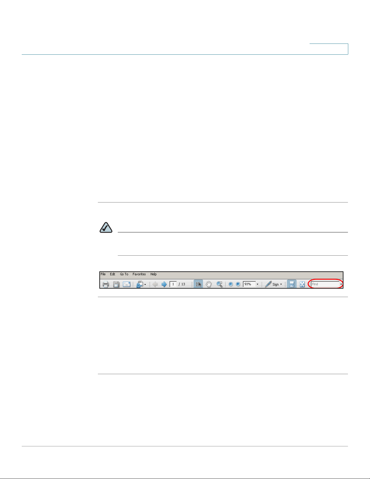
STEP 1 Enter your search terms in the Find text box on the toolbar.
NOTE By default, the Find tool is available at the right end of the Acrobat toolbar. If
the Find tool does not appear, choose Edit > Find.
STEP 2 Optionally, click the arrow next to the Find text box to refine your search by
choosing special options such as Whole Words Only.
STEP 3 Press Enter.
STEP 4 Acrobat displays the first instance of the search term.
STEP 5 Press Enter again to continue to more instances of the term.
Preface
ATA Administration Guide xiv
Finding Text in Multiple PDF Files
The
Search
window lets you search for terms in multiple PDF files that are stored
on your PC or local network. The PDF files do not need to be open.
STEP 1 Start Acrobat Professional or Adobe Reader.
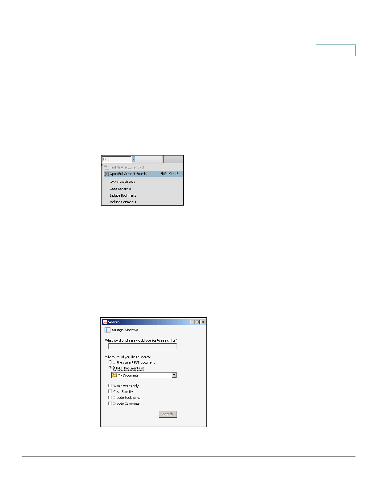
STEP 2 Choose Edit > Search, or click the arrow next to the
Find
box and then choose
Open Full Acrobat Search.
STEP 3 In the
Search
window, complete the following steps:
a. Enter the text that you want to find.
b. Choose All PDF Documents in.
From the drop-down box, choose Browse for Location. Then choose the
location on your computer or local network, and click OK.
c. If you want to specify additional search criteria, click Use Advanced Search
Options, and choose the options you want.
d. Click Search.
Preface
ATA Administration Guide xv
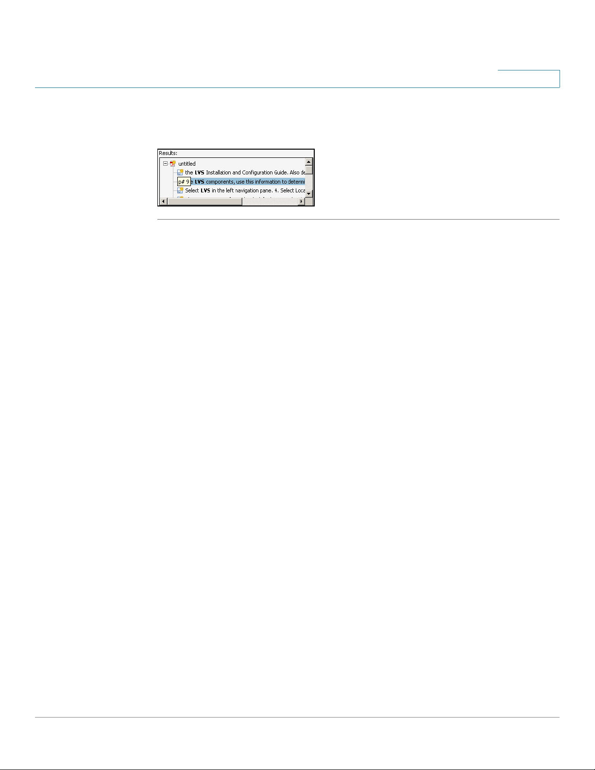
STEP 4 When the Results appear, click + to open a folder, and then click any link to open
the file where the search terms appear.
For more information about the Find and Search functions, see the Adobe Acrobat
online help.
1
ATA Administration Guide 16
Introducing Cisco Small Business Analog
Telephone Adapters
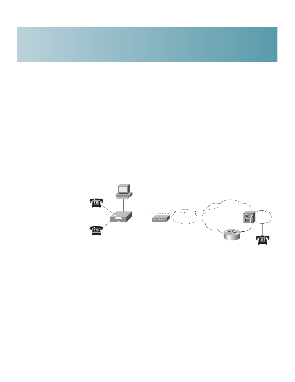
This guide describes the administration and use of Cisco Small Business analog
telephone adapters (ATAs). These ATA devices are a key element in the end-to-
end IP Telephony solution. An ATA device provides user access to Internet phone
services through one or more standard telephone RJ-11 phone ports using
standard analog telephone equipment. The ATA device connects to a wide area IP
network, such as the Internet, through a broadband (DSL or cable) modem or
router.
This chapter introduces the functionality of the ATA devices and describes the
features that are available.
Refer to the following topics:
• “Comparison of ATA Devices,” on page17
• “ATA Connectivity Requirements,” on page 20
• “ATA Software Features,” on page 25
Linksys ATA
Telephone/fax
Ethernet
Broadband CPE
(DSL, cable,
fixed wireless)
Broadband
SIP proxy
Layer 3
IP infrastructure
PSTN
Voice
gateway
187254
V
V
V

Introducing Cisco Small Business Analog Telephone Adapters
Comparison of ATA Devices
ATA Administration Guide 17
1
Comparison of ATA Devices
Each ATA device is an intelligent low-density Voice over IP (VoIP) gateway that
enables carrier-class residential and business IP Telephony services delivered
over broadband or high-speed Internet connections. An ATA device maintains the
state of each call it terminates and makes the proper reaction to user input events
(such as on/off hook or hook flash). The ATA devices use the Session Initiation
Protocol (SIP) open standard so there is little or no involvement by a “middle-man”
server or media gateway controller. SIP allows interoperation with all ITSPs that
support SIP.
The following table summarizes the ports and features provided by the ATA
devices described in this document.
Product
Name
FXS
(Analog
Phone)
FXO
PSTN
RJ-45
Internet
(WAN)
RJ-45
Ethernet
(LAN)
Voice
Lines
Description
PAP2T 2 — 1 — 2 Voice adapter with
two FXS ports.
SPA2102 2 — 1 1 2 Voice adapter with
router.
SPA3102 1 1 1 1 1 Voice adapter with
router and PSTN
connectivity.
SPA8000 8 — 1 Mainte-
nance
only
8 Voice adapter with
support for up to
eight FXS devices.
Supports SIP
Trunking for inbound
call routing to trunk
groups.
WRP400 2 — 1 4 2 Wireless-G IP router
with two FXS ports.
Provides ATA device
functionality. Can be
remotely
provisioned.
WRTP54G 2 — 1 4 2 Wireless-G IP router
with two FXS ports.
Provides ATA device
functionality.

Introducing Cisco Small Business Analog Telephone Adapters
Comparison of ATA Devices
ATA Administration Guide 18
1
NOTE The information contained in this guide is not a warranty from Cisco. Customers
planning to use ATA devices in a VoIP service deployment are advised to test all
functionality they plan to support before putting the ATA device in service. By
implementing ATA devices with the SIP protocol, intelligent endpoints at the edges
of a network perform the bulk of the call processing. This allows the deployment of
a large network with thousands of subscribers without complicated, expensive
servers.
The following figure illustrates how the different ATA devices provide voice
connectivity in a VoIP network.
Introducing Cisco Small Business Analog Telephone Adapters
Comparison of ATA Devices
ATA Administration Guide 19
1
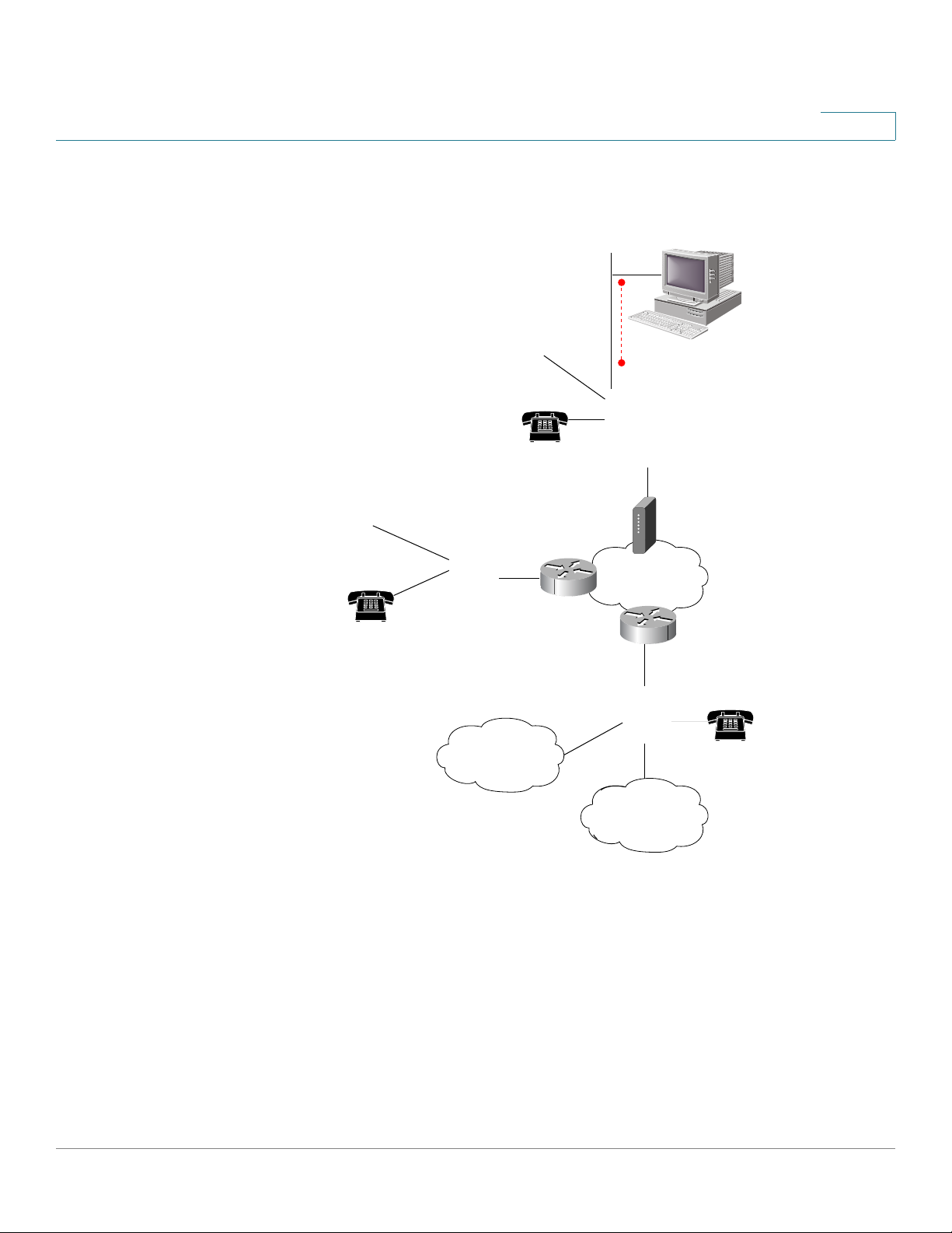
Figure1 How ATAs Provide Voice Connectivity
• The SPA3102 and SPA8000 act as SIP-PSTN gateways. They provide PSTN
connectivity in addition to a single FXS port.
• The WRP400 and WRTP54G routers provide ports for analog telephone
devices and provide QoS in the form of priority packet queueing.
SPA3102
Broadband
router
Broadband
router
SPA8000,
PAP2T
DSL/cable
modem
WRP400,
WRTP54G,
and SPA2102
Ethernet/Wireless
LAN
Fax (up to 4
SPA8000)
Analog phone
(up to 8 with
SPA8000)
PSTN
Ethernet/Wired
LAN
Internet
187255-revised

Introducing Cisco Small Business Analog Telephone Adapters
ATA Connectivity Requirements
ATA Administration Guide 20
1
ATA Connectivity Requirements
An ATA device can be connected to a local router, or directly to the Internet. Each
phone connected to an RJ-11 (analog) port on the ATA device connects to other
devices through SIP, which is transmitted over the IP network.
In order to ensure connectivity between the devices connected to its FXS ports,
the ATA device requires the following functionality to be supplied on the network
connected to its Ethernet port:
• Connection to an IP router with hairpinning support
• Connection to an outbound Proxy server
When a phone connected to the ATA device communicates with another phone, it
sends a SIP packet onto the internal LAN. The packet is then forwarded to the
external LAN or directly to the Internet. The source address and source port on the
original packet are assigned by the ATA device DHCP server. The address and
port are translated by the ATA device using Network Address Translation (NAT)
and Port Address Translation (PAT). The packet is then routed back to the internal
network on the ATA device by the local router or the ISP router.
Problems can occur with calls between phones connected to the ATA device
when an outbound proxy or a router with hairpinning support is not available. The
ATA device cannot directly connect the two telephone devices, but requires a
local or remote router to route the packet back to its destination on the local
network from which it originated.
The necessary routing can be provided by a router with hairpinning support, or by
an outbound SIP proxy, which is typically provided by the Internet Telephony
Service Provider (ITSP). When relying on the ITSP for interconnecting phones on
the ATA device, local phones connected to the ATA device are unable to
communicate with each other if the Internet connection is not available for any
reason. It is recommended you connect the ATA device to a local router that
provides hairpinning support to prevent this problem.
Introducing Cisco Small Business Analog Telephone Adapters
ATA Connectivity Requirements
ATA Administration Guide 21
1
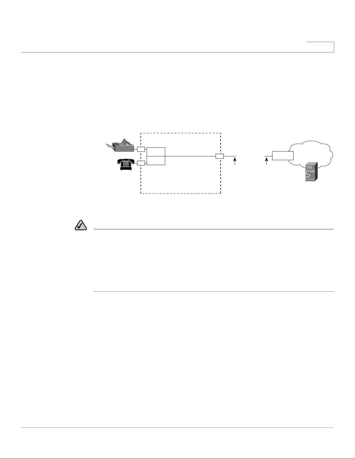
PAP2T Connectivity
As shown in the following figure, the PAP2T has two FXS ports (voice lines 1 and
2).
NOTE
• The IVR functions are accessed by connecting an analog telephone to Line 1.
• For proper operation, the service provider should use an Outbound Proxy to
forward all voice traffic when the PAP2T is located behind a router. If
necessary, explicit port ranges can be specified for SIP and RTP.
Line 1
Line 2
Internet
IP Router (with
hairpinning) or
Broadband mode
m
ITSP
ISP
PAP2T
LAN WAN
Ethernet
port
Administrative
IVR (Line 1 or
Line 2)
IP
IP
Introducing Cisco Small Business Analog Telephone Adapters
ATA Connectivity Requirements
ATA Administration Guide 22
1
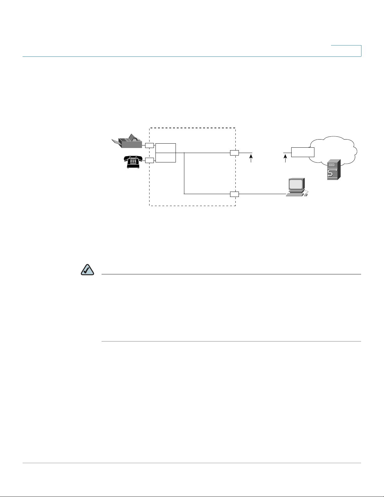
SPA2102 Connectivity
As shown in the following illustration, the SPA2102 has two FXS ports (voice lines
1 and 2).
By default, the device attached to the LAN port is assigned the network address
192.168.0.0 with a subnet mask of 255.255.255.0. If there is a network address
conflict with a device on the Ethernet port, the network address of the device on
the LAN port is automatically changed to 192.168.1.0.
NOTE
• The IVR functions are accessed by connecting an analog telephone to Line 1.
• For proper operation, the service provider should use an Outbound Proxy to
forward all voice traffic when the SPA2102 is located behind a router. If
necessary, explicit port ranges can be specified for SIP and RTP.
Line 1
Line 2
Internet
IP Router (with
hairpinning) or
Broadband mode
m
ITSP
ISP
SPA
2102
LAN
WAN
Ethernet
port
LAN
port
Administrative
IVR (Line 1 or
Line 2)
IP
IP
Administration
PC
187257
Introducing Cisco Small Business Analog Telephone Adapters
ATA Connectivity Requirements
ATA Administration Guide 23
1
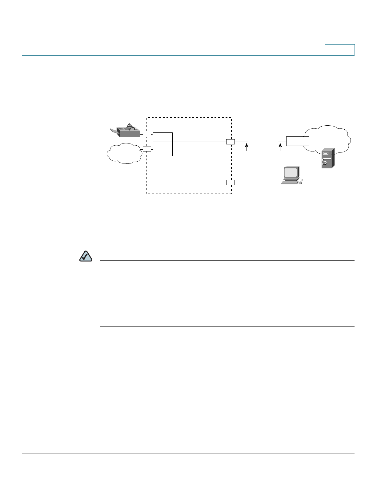
SPA3102 Connectivity
As shown in the following figure, the SPA3102 has one FXS port (voice line 1).
By default, the device on the LAN port is assigned the network address
192.168.0.0 with a subnet mask of 255.255.255.0. If there is a network address
conflict with a device on the Ethernet port, the network address of the device on
the LAN port is automatically changed to 192.168.1.0.
NOTE
• The IVR functions are accessed by connecting an analog telephone to Line 1.
• For proper operation, the service provider should use an Outbound Proxy to
forward all voice traffic when the SPA3102 is located behind a router. If
necessary, explicit port ranges can be specified for SIP and RTP.
Line 1
PSTN
Line 1
Internet
IP Router (with
hairpinning) or
Broadband mode
m
ITSP
ISP
SPA
3102
Ethernet
port
LAN
port
LAN WAN
Administrative
IVR (Line 1 or
Line 2)
IP
IP
Administration
PC
187259
PSTN
Introducing Cisco Small Business Analog Telephone Adapters
ATA Connectivity Requirements
ATA Administration Guide 24
1
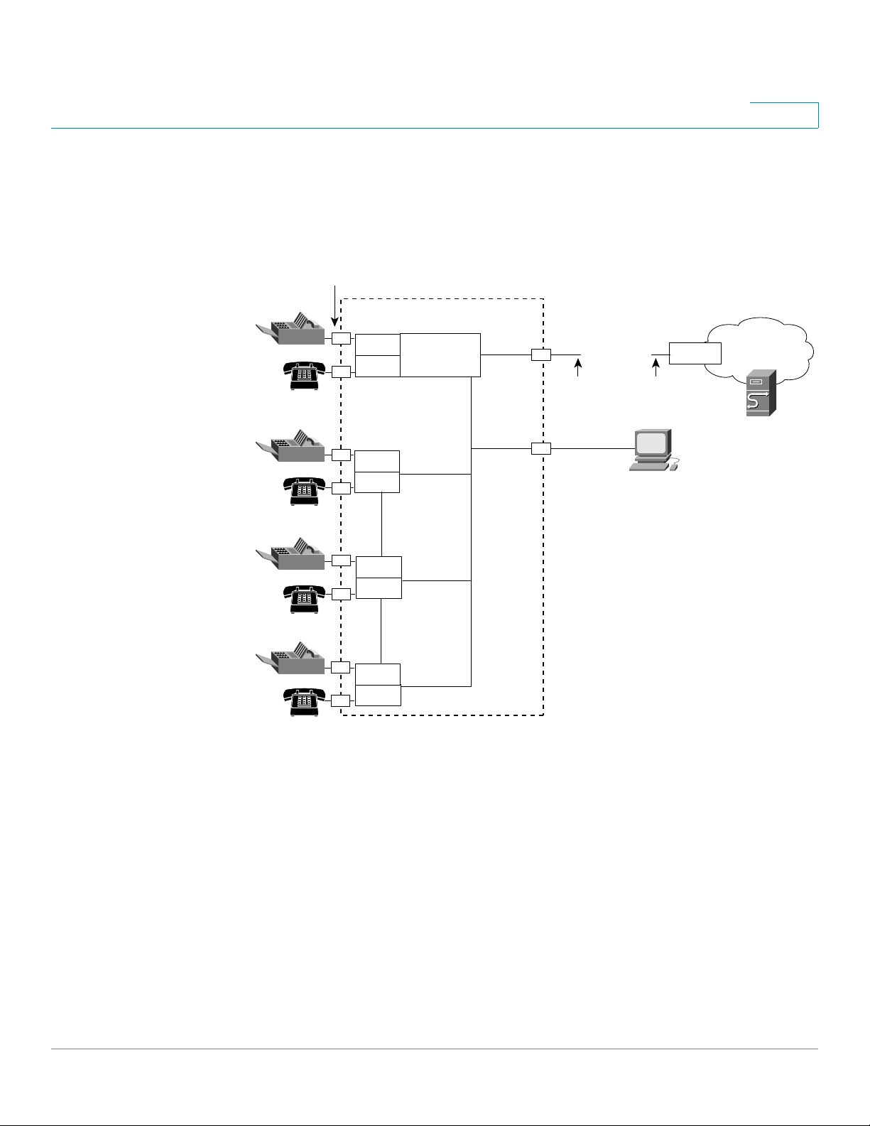
SPA8000 Connectivity
As shown in the following illustration, the SPA8000 consists of eight voice ports
(voice lines 1-8).
By default, the device on the AUX port is assigned the network address
192.168.0.0 with a subnet mask of 255.255.255.0. If there is a network address
conflict with a device on the Ethernet port, the network address of the device on
the AUX port is automatically changed to 192.168.1.0.
In the illustration, one fax machine is connected to each pair of ports to illustrate
that only one T.38 connection is supported by each of the four pairs of RJ-11 ports.
Up to four fax machines can be connected to the SPA8000 router, but they must be
distributed as shown.
Line 1
Line 2
Internet
IP Router (with
hairpinning) or
Broadband modem
ITSP
ISP
SPA800
0
Line 4
Line 3
Line 6
Line 5
Line 8
Line 7
NAT/PAT
Internal DHCP
server
LAN WAN
Ethernet
port
AUX
port
Administrative
IVR (Line 1 or
Line 2
)
IP
IP
8 FXS (RJ-11/RJ-21 ) ports
Administration
PC

Introducing Cisco Small Business Analog Telephone Adapters
ATA S of t w ar e F ea tur es
ATA Administration Guide 25
1
NOTE
• With the SPA8000, use line 1 or line 2 to access the IVR functions. See the
SPA8000 Quick Installation Guide for IVR instructions.
• For proper operation, the service provider should use an Outbound Proxy to
forward all voice traffic when the SPA8000 is located behind a router. If
necessary, explicit port ranges can be specified for SIP and RTP.
• The SPA8000 is not designed to forward IP packets to devices connected to its
AUX port and that configuration is not supported.
• The SPA8000 also can be configured with trunk groups and trunk lines. See
“SIP Trunking and Hunt Groups on the SPA8000,” on page 77.
ATA Software Features
The ATA device is a full featured, fully programmable phone adapter that can be
custom provisioned within a wide range of configuration parameters. This section
contains a high-level overview of features to provide a basic understanding of the
feature breadth and capabilities of the ATA device.
The following sections describe the factors that contribute to voice quality:
• “Voice Supported Codecs,” on page 25
• “SIP Proxy Redundancy,” on page 27
• “Other ATA Software Features,” on page 27
Voice Supported Codecs
Negotiation of the optimal voice codec sometimes depends on the ability of the
ATA device to match a codec name with the codec used by the far-end device.
The ATA device allows the network administrator to individually name the various
codecs that are supported so that the ATA device can successfully negotiate the
codec with the far-end equipment. The administrator can select which low-bit-rate

Introducing Cisco Small Business Analog Telephone Adapters
ATA S of t w ar e F ea tur es
ATA Administration Guide 26
1
codec is to be used for each line. G.711a and G.711u are always enabled.
Configure your preferred codec in the (FXS) tab in the Administration Web Server.
See “ATA Voice Field Reference,” on page121. See also “Supported Codecs,” on
page 54 for a list of which codecs are supported on each ATA device.
NOTE When no static payload value is assigned per RFC 1890, the ATA device can
support dynamic payloads for G.726.
Codec (Voice Compression
Algorithm)
Description
G.711 (A-law and mμ-law) This very low complexity codec supports
uncompressed 64 kbps digitized voice transmission at
one through ten 5 ms voice frames per packet. This
codec provides the highest voice quality and uses the
most bandwidth of any of the available codecs.
G.726 This low complexity codec supports compressed 16,
24, 32, and 40 kbps digitized voice transmission at one
through ten 10 ms voice frames per packet. This codec
provides high voice quality.
G.729a The ITU G.729 voice coding algorithm is used to
compress digitized speech. Cisco supports G.729.
G.729a is a reduced complexity version of G.729. It
requires about half the processing power to code
G.729. The G.729 and G.729a bit streams are
compatible and interoperable, but not identical.
G.723.1 The ATA device supports the use of ITU G.723.1 audio
codec at 6.4 kbps. Up to two channels of G.723.1 can be
used simultaneously. For example, Line 1 and Line 2 can
be using G.723.1 simultaneously, or Line 1 or Line 2 can
initiate a three-way conference with both call legs using
G.723.1.
NOTE: The WRP400 device does not support the
G.723.1 audio codec.

Introducing Cisco Small Business Analog Telephone Adapters
ATA S of t w ar e F ea tur es
ATA Administration Guide 27
1
SIP Proxy Redundancy
In typical commercial IP Telephony deployments, all calls are established through
a SIP proxy server. An average SIP proxy server may handle thousands of
subscribers. It is important that a backup server be available so that an active
server can be temporarily switched out for maintenance. The ATA device supports
the use of backup SIP proxy servers (via DNS SRV) so that service disruption
should be nearly eliminated.
A relatively simple way to support proxy redundancy is to configure your DNS
server with a list of SIP proxy addresses. The ATA device can be instructed to
contact a SIP proxy server in a domain named in the SIP message. The ATA device
consults the DNS server to get a list of hosts in the given domain that provides SIP
services. If an entry exists, the DNS server returns an SRV record that contains a
list of SIP proxy servers for the domain, with their host names, priority, listening
ports, and so on. The ATA device tries to contact the list of hosts in the order of
their stated priority.
If the ATA device is currently using a lower priority proxy server, it periodically
probes the higher priority proxy to see whether it is back on line, and switches
back to the higher priority proxy when possible. SIP Proxy Redundancy is
configured in the Line and PSTN Line tabs in the Administration Web Server. See
“ATA Routing Field Reference,” on page111.
Other ATA Software Features
The following table summarizes other features provided by ATA devices.
Feature Description
Streaming Audio
Server
See “Configuring a Streaming Audio Server,” on page 90.
T.38 Fax Relay See “Using a FAX Machine (SPA2102, SPA3102 or
SPA8000),” on page 55.
Silence
Suppression
See “Silence Suppression and Comfort Noise
Generation,” on page 60.

Introducing Cisco Small Business Analog Telephone Adapters
ATA S of t w ar e F ea tur es
ATA Administration Guide 28
1
Modem and Fax
Pass-Through
• Modem pass-through mode can be triggered only by
predialing the number set in the
Modem Line Toggle Code.
(Set in the Regional tab.)
• FAX pass-through mode is triggered by a CED/CNG tone or
an NSE event.
• Echo canceller is automatically disabled for Modem pass-
through mode.
• Echo canceller is disabled for FAX pass-through if the
parameter
FAX Di sa ble ECAN
(Line 1 or 2 tab) is set to “yes”
for that line (in that case FAX pass-through is the same as
Modem pass-through).
• Call waiting and silence suppression is automatically
disabled for both FAX and Modem pass-through. In addition,
out-of-band DTMF Tx is disabled during modem or fax pass-
through.
Adaptive Jitter
Buffer
The ATA device can buffer incoming voice packets to
minimize out-of-order packet arrival. This process is
known as jitter buffering. The jitter buffer size proactively
adjusts or adapts in size, depending on changing network
conditions.
The ATA device has a Network Jitter Level control setting
for each line of service. The jitter level determines how
aggressively the ATA device tries to shrink the jitter buffer
over time to achieve a lower overall delay. If the jitter level
is higher, it shrinks more gradually. If jitter level is lower, it
shrinks more quickly.
Adaptive Jitter Buffer is configured in the Line and PSTN
Line tabs. See “ATA Voice Field Reference,” on page121.
International Caller
ID Delivery
In addition to support of the Bellcore (FSK) and Swedish/
Danish (DTMF) methods of Caller ID (CID) delivery, ATAs
provide a large subset of ETSI-compliant methods to
support international CID equipment. International CID is
configured in the Line and PSTN Line tabs. See “ATA Voice
Field Reference,” on page121.
Secure Calls A user (if enabled by service provider or administrator)
has the option to make an outbound call secure in the
sense that the audio packets in both directions are
encrypted. See ”Secure Call Implementation” section on
page 72.
Feature Description
Loading...