


 Loading...
Quick Start Guide
Cisco Small Business
SLM2048, SLM2024, SLM248G, SLM248P, SLM224G,
SLM224P Smart Switch
Package Contents
•Smart Switch
•Power Cord
•Rubber feet
•Quick Start Guide
•Mounting Hardware
•Product CD-ROM
Welcome
Thank you for choosing the Cisco Small Business Series Smart Gigabit Switch. The Smart Switches offer the following interfaces:
•The SLM2024 and SLM2048 offer twenty four (24) or forty eight (48) gigabit copper ports, with two (2) shared copper or optical (SFP) uplink interfaces for connecting the switch to the core network.
•The SLM224G, SLM224P, SLM248G, and SLM248P offer twenty four (24) or forty eight (48) 10/100 copper ports, with two (2) shared gigabit copper or optical (SFP) uplink interfaces for connecting the switch to the core network.
This guide describes how to physically install your Smart Switch, connect network devices, and launch the Web-based configuration utility.
1 Getting to Know the Switch
SLM2024 and SLM2048
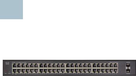
The following section describes the SLM2024 and SLM2048 switches. The front panel of the SLM2048 is shown.
Front Panel
Gigabit — (1-24 or 1-48) (Amber) Lights up to indicate a functional 1000 Mbps connection on the corresponding port (1 through 24 or 48) to an attached device.
To establish a gigabit Ethernet connection by using a miniGBIC port, you must install a MGBT1, MGBSX1, or MGBLH1 gigabit expansion module and use Category 5e cabling or fiber optic cabling.
Cisco Small Business SLM Series Smart Switch Installation Guide |
1 |
To establish a Fast Ethernet connection using a miniGBIC port, you will need to install a MFEFX1 (100BASE-FX) or MFELX1 (100BASE-LX) 100SFP transceiver and use fiber optic cabling.
NOTE On the SLM2024 and SLM2048, miniGBIC ports are shared with standard ports. If a miniGBIC port is used, then the shared standard port on the switch cannot be used. The following table defines the shared port mapping of the SLM2024 and SLM2048 switch.
Switch Model |
miniGBIC Port |
Standard Port |
|
|
|
SLM2024 |
miniGBIC 1 |
Port 12 |
|
|
|
SLM2024 |
miniGBIC 2 |
Port 24 |
|
|
|
SLM2048 |
miniGBIC 1 |
Port 24 |
|
|
|
SLM2048 |
miniGBIC 2 |
Port 48 |
|
|
|
SLM248G, SLM248P, SLM224G, and SLM224P
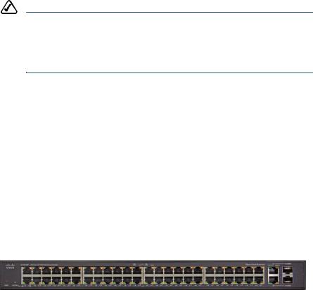
The following section describes the SLM248G, SLM248P, SLM224G, and SLM224P switches. The front panel of the SLM248P is shown.
Front Panel
PoE — (Amber) Blinks to indicate that power is being supplied to a device attached to the corresponding port. PoE is available on:
•SLM224P ports 1-6, and 13-18
•SLM248P ports 1-12, and 25-36
100M (1-24 or 1-48) — (Amber) Appears on the “G” models of the switch on each port, and lights up to indicate a functional 100 Mbps connection on the corresponding port with an attached device. Appears on the “P” models of the switch only on the non-PoE ports:
•SLM224P ports 7-12, and 19-24
•SLM248P ports 13-24, and 37-48
Gigabit — (G1-G2) (Amber) Lights up to indicate a functional 1000 Mbps connection on the corresponding port (G1-G2) with an attached device.
2 |
Cisco Small Business SLM Series Smart Switch Installation Guide |

G1-G2 — The switch is equipped with two autosensing gigabit Ethernet network ports, which use RJ-45 connectors. The gigabit Ethernet ports support network speeds of 10 Mbps, 100 Mbps, or 1000 Mbps. They can operate in halfand full-duplex modes. Auto-sensing technology enables each port to automatically detect the speed of the device connected to it (10 Mbps, 100 Mbps, or 1000 Mbps), and adjust its speed and duplex accordingly.
To establish a gigabit Ethernet connection using a miniGBIC port, you must install a MGBT1, MGBSX1, or MGBLH1 gigabit expansion module and use Category 5e cabling or fiber optic cabling. To establish a Fast Ethernet connection using a miniGBIC port, you must install a MFEFX1 (100BASEFX) or MFELX1 (100BASE-LX) 100SFP transceiver and use fiber optic cabling.
NOTE On the SLM248G, SLM248P, SLM224G, and SLM224P switches, miniGBIC ports are shared with standard ports. If a miniGBIC port is used, the shared standard port on the switch cannot be used. The following table defines the shared port mapping of the switch.
Switch Model |
miniGBIC Port |
Standard Port |
|
|
|
SLM248G/P |
miniGBIC 1 |
Port G1 |
|
|
|
SLM248G/P |
miniGBIC 2 |
Port G2 |
|
|
|
SLM224G/P |
miniGBIC 1 |
Port G1 |
|
|
|
SLM224G/P |
miniGBIC 2 |
Port G2 |
|
|
|
LEDs and Ports Common to all Switch Models
System — (Green) Lights up to indicate that the switch is powered on. Blinks while the switch is performing a system self-test.
LNK/ACT — (Green) Lights up to indicate a functional network link through the corresponding port to an attached device. Blinks to indicate that the switch is actively sending or receiving data through that port.
Reset — Press and hold the Reset Button for less than ten seconds to reboot the switch. Press and hold the Reset Button for more than ten seconds to reset the switch’s settings to the factory defaults.
Ethernet (1-24 or 1-48) The switch is equipped with 24 or 48 autosensing, Ethernet ports, which use RJ-45 connectors. The Fast Ethernet ports support network speeds of 10 Mbps or 100 Mbps. They can operate
Cisco Small Business SLM Series Smart Switch Installation Guide |
3 |
Loading...