


 Loading...
Installing Power Boards in Cisco Ethernet
Switch Network Modules
Product Numbers: PPWR-DCARD-16ESW, PPWR-DCARD-36ESW
This document describes how to install the optional power board for the Cisco Ethernet switch network module if external -48V power for IP telephones is required.
Network module installation documents provide detailed instructions for network module installation and cabling. You can access these documents at: Cisco Product Documentation > Access Servers and Access Routers > Modular Access Routers > Cisco platform you are using> Hardware installation documents for Cisco platform you are using > Network module (netmod) installation
This document contains the following sections:
•Safety Information, page 1
•Tools and Equipment Needed, page 2
•Adding an Optional Power Board, page 2
•Obtaining Documentation, page 4
•Obtaining Technical Assistance, page 5
Safety Information
For safety information you need to know before working on your Cisco router, see the Regulatory Compliance and Safety Information document that accompanied this device.
Warning Only trained and qualified personnel should be allowed to install or replace this equipment. To see translations of the warnings that appear in this publication, refer to the Regulatory Compliance and Safety Information document that accompanied this device.
Caution Electrostatic discharge (ESD) can damage equipment and impair electrical circuitry. Always follow ESD prevention procedures when removing and replacing cards.
Corporate Headquarters:
Cisco Systems, Inc., 170 West Tasman Drive, San Jose, CA 95134-1706 USA
Copyright © 2002. Cisco Systems, Inc. All rights reserved.
Tools and Equipment Needed
Tools and Equipment Needed
You need the following tools and equipment to remove and install Compact Flash memory cards:
•ESD-preventive wrist strap
•Antistatic bag or mat
•Number 2 Phillips screwdriver or flat-blade screwdriver
Adding an Optional Power Board
An optional power board can be used if the Ethernet switch network module requires external -48V power for IP telephones. Installation and configuration of the external power suppy system is described in the Cisco External Power Supply for Cisco Ethernet Switch Network Modules Installation Guide. Use the Cisco Network Modules Hardware Installation Guide and platform hardware installation guide for more information.
Follow this procedure to install power boards:
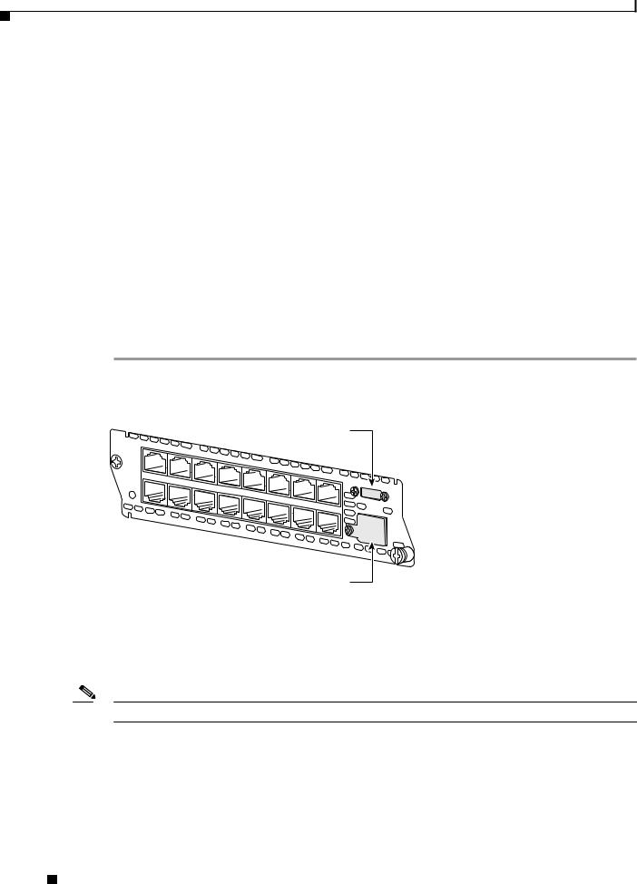
Step 1 Use a Philips screwdriver to remove the cover on the external power board port, as shown in Figure 1.
Figure 1 Power Board Port Cover on the Ethernet Switch Network Module
NMESW- 16
|
|
|
External power supply port cover |
|
|
||||||||||||
15x |
|
|
|
|
|
|
|
|
|
|
|
|
|
|
|
|
|
|
|
|
|
|
|
FastEthernet |
|
|
|
|
|
|
|
|
|
||
|
|
|
|
|
|
|
|
Ports |
|
|
|
|
|
|
|
|
|
|
|
|
|
|
|
|
|
|
|
|
|
|
|
|
8x |
|
|
7x |
|
|
|
|
|
|
|
|
|
|
|
|
|
|
|
|
Ext |
|
|
|
|
|
|
|
|
|
|
|
|
|
|
|
|
Pwr |
|
15x |
|
|
|
|
|
|
|
|
|
|
|
|
|
|
|
-48V |
GE |
7x |
|
|
|
|
|
|
|
|
|
|
|
|
|
|
|
||
14x |
6x |
|
|
|
|
|
|
|
|
|
|
|
|
|
10/100/ |
||
|
|
|
|
|
|
|
|
|
|
|
|
|
|
||||
|
|
|
|
|
|
|
|
|
|
|
|
|
|
|
|||
|
|
|
13x |
5x |
|
|
|
|
|
|
|
|
|
|
|
1000 |
|
|
|
|
|
|
|
|
|
|
|
|
|
|
|
|
|||
|
|
|
|
|
12x |
4x |
11x |
|
|
|
|
|
|
|
|
Base-Tx |
|
|
|
|
|
|
|
|
|
|
|
|
|
|
|
||||
|
|
|
|
|
|
|
3x |
|
|
|
|
|
|
|
EN |
||
|
|
|
|
|
|
|
|
10x |
2x |
|
|
|
0x |
|
|||
|
|
|
|
|
|
|
|
|
|
|
9x |
1x |
8x |
|
|
|
|
|
|
|
|
|
|
|
|
|
|
|
|
0x |
|
|
|||
|
|
|
|
|
|
|
|
|
|
|
|
|
|
|
|||
|
|
|
|
|
|
|
|
|
|
|
|
|
|
|
|
||
|
|
|
|
|
|
|
|
|
|
|
|
|
|
|
|
|
|
62426
Gigabit Ethernet port cover
Step 2 Remove the thumbscrews on either side of the power board port. Put these in a safe place as they will be replaced once the power board is installed.
Step 3 Guide the external connector through the power board port opening on the card faceplate.
Step 4 Insert the connector on the power board into the connector on the network module. See Figure 2 for 16-port Ethernet switch network modules and Figure 3 for 36-port Ethernet switch network modules.
Note Be sure to press firmly on the power board until the board seats onto the connector.
Step 5 Insert the screws from the board installation kit through the power board into the standoffs on the network module.
Step 6 Replace the thumbscrews on either side of the power board port. Make sure the thumbscrews are tightened firmly.
Installing Power Boards in Cisco Ethernet Switch Network Modules
2 |
78-14282-02 |
|
|

Adding an Optional Power Board
Warning Do not connect the external power supply cable to the power connector on the front of the network module until the network module has been inserted into the router chassis. To see translations of the warnings that appear in this publication, refer to the Regulatory Compliance and Safety Information document that accompanied this device.
Step 7 After installing the network module into the chassis, connect the power cable to the power module connector on the front of the network module. See the Cisco External Power Supply for Cisco Ethernet Switch Network Modules Installation Guide for more information.
Figure 2 Installing a Power Board in a 16-Port Ethernet Switch Network Module
NMESW 16 -
15x
7x
|
|
|
FastEthernet |
Ports |
|
||
15x |
7x |
|
|
|
|
||
|
|
|
|
|
|
||
|
|
|
|
|
|
|
|
|
14x |
6x |
|
|
|
|
|
|
|
|
|
|
|
|
|
|
|
13x |
5x |
|
|
|
|
|
|
|
|
|
|
|
|
|
|
|
12x |
4x |
|
|
|
|
|
|
|
|
|
|
|
|
|
|
|
11x |
3x |
|
|
|
|
|
|
|
|
|
|
|
|
|
|
|
|
10x |
2x |
|
|
|
|
|
|
|
|
|
|
|
|
|
|
|
9x |
|
|
|
|
|
|
|
1x |
8x 0x
8x
0x
-48V
Ext
Pwr
GE 10/100/1000 Base-Tx EN
62350
Installing Power Boards in Cisco Ethernet Switch Network Modules
|
78-14282-02 |
3 |
|
|
|
Loading...