


PA-2H Dual-Port HSSI Port Adapter
Installation and Configuration
Product Numbers: PA-2H and PA-2H=
Platforms Supported: Cisco 7200 Series (including a Cisco 7206 as a router shelf in a Cisco AS5800 Universal Access Server), Cisco 7000 Series and Cisco 7500 Series with VIP2, Cisco uBR7200 Series, and the
Catalyst RSM/VIP2 on the Catalyst 5000 Family Switches
Corporate Headquarters
Cisco Systems, Inc. 170 West Tasman Drive
San Jose, CA 95134-1706 USA http://www.cisco.com
Tel: 408 526-4000
800 553-NETS (6387) Fax: 408 526-4100
Text Part Number: 78-4771-06
THE SPECIFICATIONS AND INFORMATION REGARDING THE PRODUCTS IN THIS MANUAL ARE SUBJECT TO CHANGE WITHOUT NOTICE. ALL STATEMENTS, INFORMATION, AND RECOMMENDATIONS IN THIS MANUAL ARE BELIEVED TO BE ACCURATE BUT ARE PRESENTED WITHOUT WARRANTY OF ANY KIND, EXPRESS OR IMPLIED. USERS MUST TAKE FULL RESPONSIBILITY FOR THEIR APPLICATION OF ANY PRODUCTS.
THE SOFTWARE LICENSE AND LIMITED WARRANTY FOR THE ACCOMPANYING PRODUCT ARE SET FORTH IN THE INFORMATION PACKET THAT SHIPPED WITH THE PRODUCT AND ARE INCORPORATED HEREIN BY THIS REFERENCE. IF YOU ARE UNABLE TO LOCATE THE SOFTWARE LICENSE OR LIMITED WARRANTY, CONTACT YOUR CISCO REPRESENTATIVE FOR A COPY.
The following information is for FCC compliance of Class A devices: This equipment has been tested and found to comply with the limits for a Class A digital device, pursuant to part 15 of the FCC rules. These limits are designed to provide reasonable protection against harmful interference when the equipment is operated in a commercial environment. This equipment generates, uses, and can radiate radio-frequency energy and, if not installed and used in accordance with the instruction manual, may cause harmful interference to radio communications. Operation of this equipment in a residential area is likely to cause harmful interference, in which case users will be required to correct the interference at their own expense.
The following information is for FCC compliance of Class B devices: The equipment described in this manual generates and may radiate radio-frequency energy. If it is not installed in accordance with Cisco’s installation instructions, it may cause interference with radio and television reception. This equipment has been tested and found to comply with the limits for a Class B digital device in accordance with the specifications in part 15 of the FCC rules. These specifications are designed to provide reasonable protection against such interference in a residential installation. However, there is no guarantee that interference will not occur in a particular installation.
Modifying the equipment without Cisco’s written authorization may result in the equipment no longer complying with FCC requirements for Class A or Class B digital devices. In that event, your right to use the equipment may be limited by FCC regulations, and you may be required to correct any interference to radio or television communications at your own expense.
You can determine whether your equipment is causing interference by turning it off. If the interference stops, it was probably caused by the Cisco equipment or one of its peripheral devices. If the equipment causes interference to radio or television reception, try to correct the interference by using one or more of the following measures:
•Turn the television or radio antenna until the interference stops.
•Move the equipment to one side or the other of the television or radio.
•Move the equipment farther away from the television or radio.
•Plug the equipment into an outlet that is on a different circuit from the television or radio. (That is, make certain the equipment and the television or radio are on circuits controlled by different circuit breakers or fuses.)
Modifications to this product not authorized by Cisco Systems, Inc. could void the FCC approval and negate your authority to operate the product.
The Cisco implementation of TCP header compression is an adaptation of a program developed by the University of California, Berkeley (UCB) as part of UCB’s public domain version of the UNIX operating system. All rights reserved. Copyright © 1981, Regents of the University of C alifornia.
NOTWITHSTANDING ANY OTHER WARRANTY HEREIN, ALL DOCUMENT FILES AND SOFTWARE OF THESE SUPPLIERS ARE PROVIDED “AS IS” WITH ALL FAULTS. CISCO AND THE ABOVE-NAMED SUPPLIERS DISCLAIM ALL WARRANTIES, EXPRESSED OR IMPLIED, INCLUDING, WITHOUT LIMITATION, THOSE OF MERCHANTABILITY, FITNESS FOR A PARTICULAR PURPOSE AND NONINFRINGEMENT OR ARISING FROM A COURSE OF DEALING, USAGE, OR TRADE PRACTICE.
IN NO EVENT SHALL CISCO OR ITS SUPPLIERS BE LIABLE FOR ANY INDIRECT, SPECIAL, CONSEQUENTIAL, OR INCIDENTAL DAMAGES, INCLUDING, WITHOUT LIMITATION, LOST PROFITS OR LOSS OR DAMAGE TO DATA ARISING OUT OF THE USE OR INABILITY TO USE THIS MANUAL, EVEN IF CISCO OR ITS SUPPLIERS HAVE BEEN ADVISED OF THE POSSIBILITY OF SUCH DAMAGES.
Access Registrar, AccessPath, Any to Any, AtmDirector, CCDA, CCDE, CCDP, CCIE, CCNA, CCNP, CCSI, CD-PAC, the Cisco logo, Cisco Certified Internetwork Expert logo, CiscoLink, the Cisco Management Connection logo, the Cisco NetWorks logo, the Cisco Powered Network logo, Cisco Systems Capital, the Cisco Systems Capital logo, Cisco Systems Networking Academy, the Cisco Technologies logo, ConnectWay, ControlStream, Fast Step, FireRunner, GigaStack, IGX, JumpStart, Kernel Proxy, MGX, Natural Network Viewer, NetSonar, Network Registrar, New World, Packet, PIX, Point and Click Internetworking, Policy Builder, Precept, RouteStream, Secure Script, ServiceWay, SlideCast, SMARTnet, StreamView, The Cell, TrafficDirector, TransPath, ViewRunner, VirtualStream, VisionWay, VlanDirector, Workgroup Director, and Workgroup Stack are trademarks; Changing the Way We Work, Live, Play, and Learn, Empowering the Internet Generation, The Internet Economy, and The New Internet Economy are service marks; and Asist, BPX, Catalyst, Cisco, Cisco IOS, the Cisco IOS logo, Cisco Systems, the Cisco Systems logo, the Cisco Systems Cisco Press logo, Enterprise/Solver, EtherChannel, EtherSwitch, FastHub, FastLink, FastPAD, FastSwitch, IOS, IP/TV, IPX, LightStream, LightSwitch, MICA, NetRanger, Registrar, StrataView Plus, Stratm, TeleRouter, and VCO are registered trademarks of Cisco Systems, Inc. in the U.S. and certain other countries. All other trademarks mentioned in this document are the property of their respective owners. The use of the word partner does not imply a partnership relationship between Cisco and any of its resellers. (9906R)
PA-2H Dual-Port HSSI Port Adapter Installation and Configuration
Copyright © 1996–1999, Cisco Systems, Inc.
All rights reserved.

About This Manual
This chapter explains the objectives and organization of the PA-2H Dual-Port HSSI Port Adapter Installation and Configuration document and defines the conventions used to convey instructions and information.
Document Objectives
This document describes the installation and configuration of the dual-port High-Speed Serial Interface (HSSI) port adapter (PA-H Rev. B), which can be used in the following platforms:
•Cisco 7200 series routers—Consisting of the 2-slot Cisco 7202, 4-slot Cisco 7204 and
Cisco 7204VXR, and the 6-slot Cisco 7206 and Cisco 7206VXR, and including a Cisco 7206 as a router shelf in a Cisco AS5800 Universal Access Server
•Cisco uBR7200 series universal broadband routers—Consisting of the 6-slot Cisco uBR7246 (4 cable modem card slots and 2 port adapter slots) and the 3-slot Cisco uBR7223 (2 cable modem card slots and 1 port adapter slot)
•Second-generation Versatile Interface Processor (VIP2)—In all Cisco 7500 series routers and in Cisco 7000 series routers using the Cisco 7000 Series Route Switch Processor (RSP7000) and Cisco 7000 Series Chassis Interface (RSP7000CI) installed
•Catalyst Route Switch Module (RSM)/VIP2—In all Catalyst 5000 family switches
Note The Cisco 7206 and Cisco 7206VXR can be used as router shelves in a Cisco AS5800 Universal Access Server. For information about the Cisco 7206 and Cisco 7206VXR as router shelves, refer to the Cisco AS5800 Universal Access Server documentation listed in the “If You Need More Information” section on page vii.
For complete descriptions of interface subcommands and the configuration options available for interfaces, and which ones support HSSI port adapter functionality, refer to the documentation resources listed in the “If You Need More Information” section on page vii.
Document Organization
This document is organized into the following chapters:
•Chapter 1, “Overview,” describes the PA-2H dual-port HSSI port adapter, illustrates its location in the supported hardware platforms, and describes its LED displays, cables, and receptacles.
About This Manual v

Cisco Connection Online
•Chapter 2, “Preparing for Installation,” is a preparatory chapter that describes safety considerations, tools required, and procedures you should perform before the actual installation.
•Chapter 3, “VIP2 and the Dual-Port HSSI Port Adapter,” provides instructions for installing the PA-2H dual-port HSSI port adapter on a VIP2 interface processor installed in a Cisco 7500 or Cisco 7000 series router.
•Chapter 4, “Catalyst RSM/VIP2 and the Dual-Port HSSI Port Adapter,” provides instructions for installing the PA-2H dual-port HSSI port adapter on a Catalyst RSM/VIP2 installed in the Catalyst 5000 family switches.
•Chapter 5, “Cisco 7200 Series and the Dual-Port HSSI Port Adapter,” provides instructions for installing the PA-2H dual-port HSSI port adapter in a Cisco 7200 series router.
•Chapter 6, “Cisco uBR7200 Series and the Dual-Port HSSI Port Adapter,” provides instructions for installing the PA-2H dual-port HSSI port adapter in Cisco uBR7200 series universal broadband routers.
•Chapter 7, “Cable Installation and Interface Configuration,” provides instructions for installing port adapter cables and configuring your port adapter on the supported platforms. The instructions given in this chapter apply to all supported platforms described in this document.
Cisco Connection Online
Cisco Connection Online (CCO) is Cisco Systems’ primary, real-time support channel. Maintenance customers and partners can self-register on CCO to obtain additional information and services.
Available 24 hours a day, 7 days a week, CCO provides a wealth of standard and value-added services to Cisco’s customers and business partners. CCO services include product information, product documentation, software updates, release notes, technical tips, the Bug Navigator, configuration notes, brochures, descriptions of service offerings, and download access to public and authorized files.
CCO serves a wide variety of users through two interfaces that are updated and enhanced simultaneously: a character-based version and a multimedia version that resides on the World Wide Web (WWW). The character-based CCO supports Zmodem, Kermit, Xmodem, FTP, and Internet e-mail, and it is excellent for quick access to information over lower bandwidths. The WWW version of CCO provides richly formatted documents with photographs, figures, graphics, and video, as well as hyperlinks to related information.
You can access CCO in the following ways:
•WWW: http://www.cisco.com
•WWW: http://www-europe.cisco.com
•WWW: http://www-china.cisco.com
•Telnet: cco.cisco.com
•Modem: From North America, 408 526-8070; from Europe, 33 1 64 46 40 82. Use the following terminal settings: VT100 emulation; databits: 8; parity: none; stop bits: 1; and connection rates up to 28.8 kbps.
For a copy of CCO’s Frequently Asked Questions (FAQ), contact cco-help@cisco.com. For additional information, contact cco-team@cisco.com.
vi PA-2H Dual-Port HSSI Port Adapter Installation and Configuration

Documentation CD-ROM
Note If you are a network administrator and need personal technical assistance with a Cisco product that is under warranty or covered by a maintenance contract, contact Cisco’s Technical Assistance Center (TAC) at 800 553-2447, 408 526-7209, or tac@cisco.com. To obtain general information about Cisco Systems, Cisco products, or upgrades, contact 800 553-6387,
408 526-7208, or cs-rep@cisco.com.
Documentation CD-ROM
Cisco documentation and additional literature are available in a CD-ROM package, which ships with your product. The Documentation CD-ROM, a member of the Cisco Connection Family, is updated monthly. Therefore, it might be more current than printed documentation. To order additional copies of the Documentation CD-ROM, contact your local sales representative or call customer service.
The CD-ROM package is available as a single package or as an annual subscription. You can also access Cisco documentation on the World Wide Web at http://www.cisco.com, http://www-china.cisco.com, or http://www-europe.cisco.com.
If you are reading Cisco product documentation on the World Wide Web, you can submit comments electronically. Click Feedback in the toolbar and select Documentation. After you complete the form, click Submit to send it to Cisco. We appreciate your comments.
If You Need More Information
Your router and the Cisco IOS software running on it contain extensive features and functionality, which are documented in the following resources:
•Cisco Documentation CD-ROM package
Cisco documentation and additional literature are available in a CD-ROM package, which ships with your product. The Documentation CD-ROM, a member of the Cisco Connection Family, is updated monthly; therefore, it might be more up to date than printed documentation. To order additional copies of the Documentation CD-ROM, contact your local sales representative or call customer service. The CD-ROM package is available as a single package or as an annual subscription.
If you are reading Cisco product documentation on the World Wide Web, you can submit comments electronically. Click Feedback on the toolbar; and then select Documentation. After you complete the form, click Submit to send it to Cisco. We appreciate your comments.
Note You can access Cisco IOS software configuration and hardware installation and maintenance documentation on the World Wide Web at http://www.cisco.com, http://www-china.cisco.com, or http://www-europe.cisco.com.
•For Cisco IOS software configuration information and support, refer to the modular configuration and modular command reference publications in the Cisco IOS software configuration documentation set that corresponds to the software release installed on your Cisco hardware.
•For hardware installation and maintenance information on the Cisco 7000 series and Cisco 7500 series routers, and the VIP2, refer to the following publications:
—The installation and configuration guide that shipped with your Cisco 7000 series or Cisco 7500 series router
About This Manual vii

If You Need More Information
—Second-Generation Versatile Interface Processor (VIP2) Installation and Configuration (for VIP2 users only)
•For hardware installation and maintenance information on the Catalyst 5000 family switches and the Catalyst RSM/VIP2, refer to the following publications:
—The installation and configuration guide that shipped with your Catalyst 5000 family switches
—Route Switch Module Catalyst VIP2-15 and VIP2-40 Installation and Configuration Note
(Document Number 78-4780-01) which shipped with your Catalyst RSM/VIP2
•For hardware installation and maintenance information on the Cisco 7200 VXR routers, refer to the Cisco 7200 VXR Installation and Configuration Guide that shipped with your
Cisco 7200 VXR router.
•For hardware installation and maintenance information on the Cisco 7200 routers, refer to the following publications that shipped with your router:
—Cisco 7202 Installation and Configuration Guide
—Cisco 7204 Installation and Configuration Guide
—Cisco 7206 Installation and Configuration Guide
•For port adapter hardware and memory configuration guidelines for the Cisco 7200 series routers (including a Cisco 7206 and Cisco 7206VXR as router shelves in the Cisco AS5800 Universal Access Server), refer to the document Cisco 7200 Series Port Adapter Hardware Configuration Guidelines.
•For hardware installation and maintenance information on the Cisco uBR7200 series universal broadband router, refer to the Cisco uBR7246 Universal Broadband Router Installation and Configuration Guide that shipped with your Cisco uBR7246 universal broadband router, or the
Cisco uBR7223 Universal Broadband Router Installation and Configuration Guide that shipped with your Cisco uBR7223.
•For hardware installation and maintenance information and software configuration information on the Cisco AS5800 Universal Access Server, refer to the following publications:
—Cisco AS5800 Universal Access Server Hardware Installation and Configuration Guide
—Cisco AS5800 Universal Access Server Software Installation and Configuration Guide
•For international agency compliance, safety, and statutory information for wide-area network (WAN) interfaces for the Cisco 7500 series, Cisco 7000 series, Cisco 7200 series routers, the Cisco uBR7200 series universal broadband routers, and the Cisco AS5800 Universal Access Server, refer to the following publications:
—Regulatory Compliance and Safety Information for the Cisco 7500 Series Routers
—Regulatory Compliance and Safety Information for the Cisco 7000 Series Routers
—Regulatory Compliance and Safety Information for the Cisco 7200 Series Routers
—Regulatory Compliance and Safety Information for the Cisco uBR7246 Universal Broadband Router or Regulatory Compliance and Safety Information for the Cisco uBR7223 Universal Broadband Router
—Cisco AS5800 Universal Access Server Regulatory Compliance and Safety Information
Note The regulatory compliance and safety information documentation listed above applies to the Catalyst 5000 family switches and the Catalyst RSM/VIP2.
viii PA-2H Dual-Port HSSI Port Adapter Installation and Configuration

If You Need More Information
•For general information about documentation, refer to the Documentation CD-ROM, the “Cisco Connection Online” section on page vi or call Customer Service at 800 553-6387 or
408 526-7208. Customer Service hours are 5:00 a.m. to 6:00 p.m. Pacific time, Monday through Friday (excluding Cisco-observed holidays). You can also send e-mail to cs-rep@cisco.com, refer to the Cisco Information Packet that shipped with your router, or access Cisco documentation on the World Wide Web at http://www.cisco.com, http://www-china.cisco.com, or http://www-europe.cisco.com.
About This Manual ix

If You Need More Information
x PA-2H Dual-Port HSSI Port Adapter Installation and Configuration
C H A P T E R 1
Overview
This chapter provides physical and functional overviews of the PA-2H dual-port high-speed serial interface (HSSI) port adapter. The chapter contains the following sections:
•
•
•
Port Adapter Overview, page 1-1
LEDs, page 1-3
Receptacles, Cables, and Pinouts, page 1-4
Port Adapter Overview
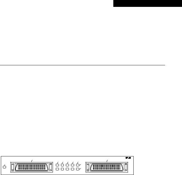
The PA-2H dual-port HSSI port adapter provides two high-speed serial interfaces. (See Figure 1-1.) The interfaces on PA-2H are considered to be data terminal equipment (DTE) devices. (Port adapters have a handle attached, but this handle is occasionally not shown in figures in this publication to allow a full view of detail on the port adapter faceplate.)
Figure 1-1 PA-2H Port Adapter (Faceplate View)
ENABLED |
0 |
|
|
|
|
0 |
1 |
|
|
TD |
TC |
RD |
RC |
LB/C |
|
|
|
|
|
|
|
1 |
|
HSSI
Rev. B
H10887
HSSI network interfaces reside on modular port adapters, which provide a direct connection between the high-speed bus in the router and the external networks. The PA-2H port adapter can be installed in the following slots on the hardware platforms described in this document:
•
•
•
VIP2—Port adapter slot 0 and port adapter slot 1
Catalyst RSM/VIP2—Port adapter slot 0 and port adapter slot 1
Cisco 7200 series routers—Port adapter slot 1 through 6 in the Cisco 7206, or slots 1 through 4 in the Cisco 7204
•Cisco uBR7200 series routers—Port adapter slot 1 or slot 2 of the Cisco uBR7246, and port adapter slot 1 for the Cisco uBR7223.
Each HSSI port is a female, 50-pin, SCSI-II-type receptacle. You must use an HSSI interface cable to connect the interface with an external data service unit (DSU). Refer to the “Receptacles, Cables, and Pinouts” section on page 1-4 for descriptions of HSSI cables.
Overview 1-1

Port Adapter Overview
The HSSI port adapter conforms to BABT/TC/130 and EIA/TIA-612 and EIA/TIA-613 standards for HSSI. PA-2H provides two interfaces. Each interface provides a full-duplex synchronous serial interface for transmitting and receiving data at rates of up to 52 megabits per second (Mbps).
The HSSI, which was recently standardized as EIA/TIA 612/613, provides access to services at T3 (45 Mbps), E3 (34 Mbps), and Synchronous Optical Network (SONET) STS-1 (51.82 Mbps) rates. The actual rate of the interface depends on the external DSU and the type of service to which it is connected.
The port adapter supports both 16and 32-bit cyclic redundancy checks (CRCs). The default is 16-bit CRCs; to enable 32-bit CRCs, you use a configuration command. (For a description of the CRC function, refer to “Chapter 7, “Cable Installation and Interface Configuration.”
Note While the VIP2 and Catalyst RSM/VIP2 supports online insertion and removal, individual port adapters do not. To replace port adapters in the Cisco 7000 series and Cisco 7500 series routers, and the Catalyst 5000 family switches, you must first remove the VIP2 or Catalyst RSM/VIP2 from the chassis, then replace port adapters as required. Online insertion and removal is supported for port adapters in the Cisco 7200 series and Cisco uBR7200 series routers.
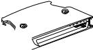
The BABT605559 marking on the HSSI port adapter signifies that the port adapter meets United Kingdom directive 605559 and has been designed to BABT/TC/130 standards. The BABT label is located on the top of each HSSI port adapter (PA-2H). Figure 1-2 shows the BABT label.
Figure 1-2 BABT Label for the HSSI Port Adapter
605559
H7823
Note PA-2H has been updated to Revision B (Rev. B).
The newest dual-port HSSI port adapter can be identified by Rev. B in the lower right corner of its front-panel label (see Figure 1-1). The older dual-port HSSI port adapter does not have Rev. B on its label (see Figure 1-3). (For specific information on software and hardware compatibility, refer to Chapter 2, “Preparing for Installation.”
Figure 1-3 Older HSSI Port Adapter (Pre-Rev. B)
ENABLED |
0 |
|
|
|
|
0 |
1 |
|
|
TD |
TC |
RD |
RC |
LB/C |
|
|
|
|
|
|
|
1 |
|
HSSI
H7443
To determine which dual-port HSSI port adapter you currently have installed, examine the front-panel label or, use the show diagbus command. (For information on using the show diagbus command, refer to Chapter 7, “Cable Installation and Interface Configuration.”)
1-2 PA-2H Dual-Port HSSI Port Adapter Installation and Configuration
LEDs
Note You should replace older PA-2H port adapters with the newer PA-2H Rev. B port adapter. Contact Cisco’s Technical Assistance Center (TAC) for replacement details. (For information on the TAC, refer to the “Cisco Connection Online” section on page vi.)
LEDs
This section provides information on the LEDs on the faceplate of the HSSI port adapter. The HSSI port adapter has two rows of five status LEDs, one row of five for each HSSI port on the port adapter (TD, TC, RD, RC, and LB/C), and one enabled LED for the port adapter. (See Figure 1-4.)
Figure 1-4 LEDs on the HSSI Port Adapter (Partial Front View of PA-2H Shown)
ENABLED |
|
|
|
|
0 |
|
|
TD |
TC |
RD |
RC |
LB/C |
|
|
|
|
|
|
1 |
H7446 |
|
|
|
|
|
|
After system initialization, the enabled LED, which is present on all interface processors, lights to indicate that the port adapter has been enabled for operation.
The following conditions must be met before the HSSI port adapter is enabled:
•The port adapter contains a valid microcode version that has successfully been downloaded.
•The port adapter is correctly connected to the backplane and receiving power in Cisco 7000 series and Cisco 7500 series routers, the Catalyst 5000 family switches, or to the midplane and receiving power in Cisco 7200 series and Cisco uBR7200 series routers.
•The bus recognizes the port adapter or HSSI-equipped VIP2 or Catalyst RSM/VIP2.
If any of these conditions is not met, or if the initialization fails for other reasons, the enabled LED does not go on.
The five additional status LEDs on the HSSI port adapter indicate the following:
•TD—When on, the transmit data LED indicates that the port adapter has been detected by, and is able to send packets to, the external DSU.
•TC—When on, the transmit clock LED indicates that the port adapter is transmitting a transmit clock signal to the external DSU. During normal operation, this signal is derived from the RT signal from the external DSU. During loopback, this signal is generated internally.
•RD—When on, the receive data LED indicates that the port adapter has detected, and is able to receive packets from, the external DSU.
•RC—When on, the receive clock LED indicates that the port adapter has detected a Receive Clock signal. During normal operation, this signal is received from the external DSU. During loopback, this signal is generated internally.
•LB/C—When green, this dual-color, loopback/connected LED indicates normal operation which means that the port adapter is properly connected to the external DSU and the TA (data terminal equipment [DTE] Available) and CA (data communications equipment [DCE] Available) signals are active. (See Table 1-1.) When yellow, this LED indicates that the port adapter is in loopback (LB) mode or is otherwise not physically connected to the DSU. When off, the port is neither connected or in loopback mode.
Overview 1-3
Receptacles, Cables, and Pinouts
Receptacles, Cables, and Pinouts
This section provides information about the HSSI cables you should use with the HSSI port adapter. Two types of cables are available for use with the HSSI port adapter: the HSSI interface cable used to connect your router to an external DSU (and HSSI network) and a null modem cable, which allows you to connect two routers back to back. Both HSSI cables are available only from Cisco systems and conform to EIA/TIA-612 and EIA/TIA-613 specifications.
HSSI Interface Cable
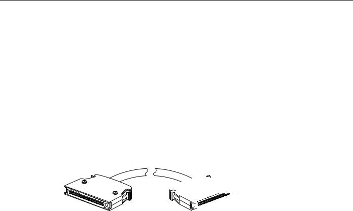
The HSSI cable (CAB-HSI1=) connects the HSSI port adapter with the external DSU. The HSSI cable is 10-feet (3.048 meters) long. The maximum HSSI cable length allowed is 50 feet (15.24 meters). Figure 1-5 shows the HSSI cable and the 50-pin connector used at each end of the HSSI cable. Table 1-1 lists the pinout.
Figure 1-5 HSSI Interface Cable and Connectors
 H5691
H5691
Table 1-1 |
HSSI Interface Cable Pinout |
|
|
|
|
|
|
|
|
|
|
|
|
|
|
Direction1 |
|
Signal Name |
|
+ Side Pin No. |
– Side Pin No. |
Router |
DSU |
|
|
|
|
|
|
SG (Signal Ground) |
1 |
26 |
— |
|
|
|
|
|
|
|
|
RT (Receive Timing) |
2 |
27 |
<— |
|
|
|
|
|
|
|
|
CA (DCE Available) |
3 |
28 |
<— |
|
|
|
|
|
|
|
|
RD (Receive Data reserved) |
4 |
29 |
<— |
|
|
|
|
|
|
|
|
LC (Loopback circuit C) |
5 |
30 |
<— |
|
|
|
|
|
|
|
|
ST (Send Timing) |
|
6 |
31 |
<— |
|
|
|
|
|
|
|
SG (Signal Ground) |
7 |
32 |
— |
|
|
|
|
|
|
|
|
TA (DTE Available) |
8 |
33 |
—> |
|
|
|
|
|
|
|
|
TT (Terminal Timing) |
9 |
34 |
—> |
|
|
|
|
|
|
|
|
LA (Loopback circuit A) |
10 |
35 |
—> |
|
|
|
|
|
|
|
|
SD (Send Data) |
|
11 |
36 |
—> |
|
|
|
|
|
|
|
LB (Loopback circuit B) |
12 |
37 |
—> |
|
|
|
|
|
|
|
|
SG (Signal Ground) |
13 |
38 |
— |
|
|
|
|
|
|
|
|
5 (Ancillary to DCE) |
14–18 |
39–43 |
—> |
|
|
|
|
|
|
|
|
SG (Signal Ground) |
19 |
44 |
— |
|
|
|
|
|
|
|
|
5 (Ancillary from DCE) |
20–24 |
45–49 |
<— |
|
|
|
|
|
|
|
|
SG (Signal Ground) |
25 |
50 |
— |
|
|
|
|
|
|
|
|
1 Router is + side (DTE). DSU is – side (DCE).
1-4 PA-2H Dual-Port HSSI Port Adapter Installation and Configuration
HSSI Null Modem Cable
HSSI Null Modem Cable
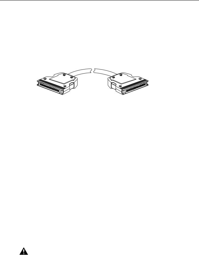
The null modem cable (CAB-HNUL=) can connect two routers directly back to back. The null modem cable is 10-feet (3.048 meters) long. Figure 1-6 shows the null modem cable. The maximum null modem cable length allowed is 50 feet (15.24 meters). The two routers must be in the same location and can be two Cisco 7000 series routers, two Cisco 7500 series routers, two Cisco 7200 series routers, two Cisco uBR7200 series routers, or any combination of each. A null modem connection allows you to verify the operation of the HSSI or to link the routers directly in order to build a larger node.
Figure 1-6 Null Modem Cable Connectors
H5692
The null modem cable uses the same 50-pin connectors as the HSSI cable, but uses the pinouts listed in Table 1-2. For connection and configuration instructions, refer to Chapter 7, “Cable Installation and Interface Configuration,” for information about attaching null modem cables.
Table 1-2 |
HSSI Null Modem Cable Pinouts |
|
|
||
|
|
|
|
|
|
Signal Name |
|
From Pins |
Direction |
To Pins |
Signal Name |
|
|
|
|
|
|
RT (Receive Timing) |
2, 27 |
—> |
9, 34 |
TT (Terminal Timing) |
|
|
|
|
|
|
|
CA (DCE available) |
3, 28 |
—> |
8, 33 |
TA (DTE Available) |
|
|
|
|
|
|
|
RD (Receive Data) |
4, 29 |
—> |
11, 36 |
SD (Send Data) |
|
|
|
|
|
|
|
LC (Loopback C) |
|
5, 30 |
—> |
10, 35 |
LA (Loopback A) |
|
|
|
|
|
|
ST (Send Timing) |
|
6, 31 |
—> |
6, 31 |
ST (Send Timing) |
|
|
|
|
|
|
TA (DTE available) |
8, 33 |
—> |
3, 28 |
CA (DCE Available) |
|
|
|
|
|
|
|
TT (Terminal Timing) |
9, 34 |
—> |
2, 27 |
RT (Receive Timing) |
|
|
|
|
|
|
|
LA (Loopback A) |
|
10, 35 |
—> |
5, 30 |
LC (Loopback C) |
|
|
|
|
|
|
SD (Send Data) |
|
11, 36 |
—> |
4, 29 |
RD (Receive Data) |
|
|
|
|
|
|
GND (Ground) |
|
1, 26, |
|
1, 26, |
GND (Ground) |
|
|
7, 32, |
|
7, 32, |
|
|
|
13, 38, |
|
13, 38, |
|
|
|
19, 44, |
|
19, 44, |
|
|
|
25, 50 |
|
25, 50 |
|
|
|
|
|
|
|
Loopback (not |
|
12, 37 |
|
|
|
connected) |
|
|
|
|
|
|
|
|
|
|
|
|
|
|
|
12, 37 |
Loopback (not connected) |
|
|
|
|
|
|
Not used |
|
14–18, 20–24, |
|
14–18, 20–24, Not used |
|
|
|
39–43, 45–49 |
|
39–43, 45–49 |
|
|
|
|
|
|
|
Caution Although the HSSI connector and the HSSI cable are similar to SCSI-II format, they are not identical. The HSSI cable specification is more restrictive than that for the SCSI-II. If a SCSI-II cable is used instead of an HSSI cable, proper operation cannot be guaranteed.
Overview 1-5

Receptacles, Cables, and Pinouts
1-6 PA-2H Dual-Port HSSI Port Adapter Installation and Configuration

C H A P T E R 2
Preparing for Installation
This chapter describes the general equipment, safety, and site preparation requirements for installing the PA-2H dual-port high-speed serial interface (HSSI) port adapters. This chapter contains the following sections:
•
•
•
•
List of Parts and Tools, page 2-1
Software and Hardware Requirements, page 2-2
Safety Guidelines, page 2-3
FCC Class B Compliance, page 2-6
List of Parts and Tools
You need the following parts and tools to install a port adapter. If you need additional equipment, contact a service representative for ordering information.
•PA-2H(=), (Revision B) dual-port HSSI port adapter and one of the following:
—VIP2-15(=), VIP2-20=, VIP2-40(=), or VIP2-50(=) motherboard
—Catalyst RSM/VIP2-15(=) or Catalyst RSM/VIP2-40(=) motherboard
—Cisco 7200 series router (including a Cisco 7206 as a router shelf in a Cisco AS5800 Universal Access Server) with at least one available port adapter slot
—Cisco uBR7200 series router with at least one available port adapter slot
•HSSI cables appropriate for the port adapter’s interfaces. (HSSI cables are available only from Cisco Systems; they are not available from outside commercial cable vendors.)
Caution Although the port adapter’s HSSI connector and the HSSI cable are similar to SCSI-II format, they are not identical. The HSSI cable specification is more restrictive than that for SCSI-II. If a SCSI-II cable is used instead of an HSSI cable, proper operation cannot be guaranteed.
•Number 1 Phillips and a 3/16-inch, flat-blade screwdriver (for VIP2 and Catalyst RSM/VIP2 installation only)
•Your own ESD-prevention equipment or the disposable grounding wrist strap included with all upgrade kits, field-replaceable units (FRUs), and spares
Preparing for Installation 2-1

Software and Hardware Requirements
Software and Hardware Requirements
Table 2-1 lists the minimum Cisco IOS software release required to use the 2H port adapters in supported router platforms.
Table 2-1 |
2H Port Adapter Software Requirements |
||
|
|
|
|
Platform |
|
Minimum Cisco IOS Release |
|
|
|
||
Cisco 7000 series and Cisco 7500 series |
|
||
|
|
|
|
• |
With VIP2-15(=) |
Cisco IOS Release 11.1(15)CA or a later release of Cisco IOS Release 11.1 CA |
|
• |
With VIP2-40(=) |
Cisco IOS Release 11.1(15)CA or a later release of Cisco IOS Release 11.1 CA |
|
• |
With VIP2-50(=) |
Cisco IOS Release 11.1(14)CA or a later release of Cisco IOS Release 11.1 CA |
|
|
|
|
|
Cisco 7200 series |
|
|
|
|
|
||
• Cisco 7204VXR, and Cisco 7206VXR |
Cisco IOS Release 12.0(2)XE2 or a later release of Cisco IOS Release 12.0 XE |
||
|
|
|
Cisco IOS Release 12.0(3)T or a later release of Cisco IOS Release 12.0 T |
• Cisco 7204 and Cisco 7206 |
Cisco IOS Release 11.1(15)CA or a later release of Cisco IOS Release 11.1 CA |
||
• |
Cisco 7202 |
|
Cisco IOS Release 11.1(19)CC1 or a later release of Cisco IOS Release 11.1 CC |
|
|
|
Cisco IOS Release 11.3(4)AA or a later release of Cisco IOS Release 11.3 AA |
• Cisco 7206 router shelf |
Cisco IOS Release 11.3(2)AA or a later release of Cisco IOS Release 11.3 AA |
||
|
|
||
Cisco uBR7200 series |
|
||
|
|
||
• Cisco uBR7246 and Cisco uBR7223 |
Cisco IOS Release 12.0(3)T or later release of Cisco IOS Release 12.0T |
||
|
|
||
Catalyst 5000 family switches |
|
||
|
|
|
|
• |
With Catalyst RSM/VIP2-15(=) |
Cisco IOS Release 11.2(15A)P or later release of Cisco IOS Release 11.2P |
|
|
|
|
|
• |
With Catalyst RSM/VIP2-40(=) |
Cisco IOS Release 11.2(15A)P or later release of Cisco IOS Release 11.2P |
|
|
|
|
|
Note In the Cisco 7200 series routers, there are specific configuration guidelines that must be observed for high-bandwidth port adapters such as the PA-2H Rev. B. For port adapter hardware and memory configuration guidelines for the Cisco 7200 series routers (including a Cisco 7206 as a router shelf in a Cisco AS5800 Universal Access Server), refer to the document, Cisco 7200 Series Port Adapter Hardware Configuration Guidelines , that shipped with your Cisco 7200 series router.
Caution The VIP2 requires that the host Cisco 7000 series router has the RSP7000 and RSP7000CI installed. The VIP2 will not operate properly with the Route Processor (RP), Switch Processor (SP), or Silicon Switch Processor (SSP) installed in the host Cisco 7000 series router.
Caution If you are using the HSSI dual-port adapter in the Catalyst 5000, 5500, 5505, or 5509 switch, you must install the port adapter on the Catalyst RSM/VIP2-15 or -40 Revision 2 (board part number 73-3468-XX, where XX is the version number). Do not use the HSSI dual-port adapter in the Catalyst 5000, 5505, or 5509 switch if you are installing it on a Catalyst RSM/VIP2-15 or -40 module that is not the Revision 2. If you fail to comply with this restriction, your system will shut down due to an overload of the power supply.
Caution You can only have two HSSI dual-port adapters per chassis when installed on a
Catalyst RSM/VIP2-15 or -40 module Revision 1 and used in the Catalyst 5500 switch.
2-2 PA-2H Dual-Port HSSI Port Adapter Installation and Configuration

Safety Guidelines
PA-2H cannot be used with a PA-A1 (Asynchronous Transfer Mode [ATM]) port adapter installed in the adjacent port adapter slot of your VIP2 or Catalyst RSM/VIP2. All other port adapters are compatible with PA-2H when installed in the adjacent port adapter slot of your VIP2 or
Catalyst RSM/VIP2.
Note PA-2H(=) is considered a high-bandwidth port adapter; therefore, and at a minimum, we recommend that the PA-2H port adapter be installed on the VIP2-15 motherboard (with 1 MB of SRAM and 8 MB of DRAM) or Catalyst RSM/VIP2-15 motherboard (with 1-MB SRAM and 16-MB DRAM).
Cisco does not recommend using PA-2H on the VIP2-10 (with 512 KB of SRAM and 8 MB of
DRAM).
Note Port adapters used with the 7200 VXR routers require the correct base hardware revision in order to function. The following error message will occur on bootup if the incorrect hardware revision is used:
> PA-3-REVNOTSUPPORTED:PA in slot 1 (Ethernet) requires base h/w revision of (1.3)
for this chassis
Use the sh diag command to display the hardware revision. (See the “Using show Commands to
Verify the New Interface Status” section on page 7-9).
Safety Guidelines
Following are safety guidelines that you should follow when working with any equipment that connects to electrical power or telephone wiring.
Safety Warnings
Safety warnings appear throughout this publication in procedures that, if performed incorrectly, might harm you. A warning symbol precedes each warning statement.
Warning This warning symbol means danger. You are in a situation that could cause bodily injury. Before you work on any equipment, be aware of the hazards involved with electrical circuitry and be familiar with standard practices for preventing accidents. To see translations of the warnings that appear in this publication, refer to the Regulatory Compliance and Safety Information document that accompanied this device.
Waarschuwing Dit waarschuwingssymbool betekent gevaar. U verkeert in een situatie die lichamelijk letsel kan veroorzaken. Voordat u aan enige apparatuur gaat werken, dient u zich bewust te zijn van de bij elektrische schakelingen betrokken risico's en dient u op de hoogte te zijn van standaard maatregelen om ongelukken te voorkomen. Voor vertalingen van de waarschuwingen die in deze publicatie verschijnen, kunt u het document Regulatory Compliance and Safety Information (Informatie over naleving van veiligheidsen andere voorschriften) raadplegen dat bij dit toestel is ingesloten.
Preparing for Installation 2-3

Safety Guidelines
Varoitus Tämä varoitusmerkki merkitsee vaaraa. Olet tilanteessa, joka voi johtaa ruumiinvammaan. Ennen kuin työskentelet minkään laitteiston parissa, ota selvää sähkökytkentöihin liittyvistä
vaaroista ja tavanomaisista onnettomuuksien ehkäisykeinoista. Tässä julkaisussa esiintyvien varoitusten käännökset löydät laitteen mukana olevasta Regulatory Compliance and Safety Information -kirjasesta (määräysten noudattaminen ja tietoa turvallisuudesta).
Attention Ce symbole d'avertissement indique un danger. Vous vous trouvez dans une situation pouvant causer des blessures ou des dommages corporels. Avant de travailler sur un équipement, soyez conscient des dangers posés par les circuits électriques et familiarisez-vous avec les procédures couramment utilisées pour éviter les accidents. Pour prendre connaissance des traductions d’avertissements figurant dans cette publication, consultez le document Regulatory Compliance and Safety Information (Conformité aux règlements et consignes de sécurité) qui accompagne cet appareil.
Warnung Dieses Warnsymbol bedeutet Gefahr. Sie befinden sich in einer Situation, die zu einer Körperverletzung führen könnte. Bevor Sie mit der Arbeit an irgendeinem Gerät beginnen, seien Sie sich der mit elektrischen Stromkreisen verbundenen Gefahren und der Standardpraktiken zur Vermeidung von Unfällen bewußt. Übersetzungen der in dieser Veröffentlichung enthaltenen Warnhinweise finden Sie im Dokument Regulatory Compliance and Safety Information
(Informationen zu behördlichen Vorschriften und Sicherheit), das zusammen mit diesem Gerät geliefert wurde.
Avvertenza Questo simbolo di avvertenza indica un pericolo. La situazione potrebbe causare infortuni alle persone. Prima di lavorare su qualsiasi apparecchiatura, occorre conoscere i pericoli relativi ai circuiti elettrici ed essere al corrente delle pratiche standard per la prevenzione di incidenti. La traduzione delle avvertenze riportate in questa pubblicazione si trova nel documento Regulatory Compliance and Safety Information (Conformità alle norme e informazioni sulla sicurezza) che accompagna questo dispositivo.
Advarsel Dette varselsymbolet betyr fare. Du befinner deg i en situasjon som kan føre til personskade. Før du utfører arbeid på utstyr, må du vare oppmerksom på de faremomentene som elektriske kretser innebærer, samt gjøre deg kjent med vanlig praksis når det gjelder å unngå ulykker. Hvis du vil se oversettelser av de advarslene som finnes i denne publikasjonen, kan du se i dokumentet Regulatory Compliance and Safety Information (Overholdelse av forskrifter og sikkerhetsinformasjon) som ble levert med denne enheten.
Aviso Este símbolo de aviso indica perigo. Encontra-se numa situação que lhe poderá causar danos físicos. Antes de começar a trabalhar com qualquer equipamento, familiarize-se com os perigos relacionados com circuitos eléctricos, e com quaisquer práticas comuns que possam prevenir possíveis acidentes. Para ver as traduções dos avisos que constam desta publicação, consulte o documento Regulatory Compliance and Safety Information (Informação de Segurança e Disposições Reguladoras) que acompanha este dispositivo.
¡Advertencia! Este símbolo de aviso significa peligro. Existe riesgo para su integridad física. Antes de manipular cualquier equipo, considerar los riesgos que entraña la corriente eléctrica y familiarizarse con los procedimientos estándar de prevención de accidentes. Para ver una traducción de las advertencias que aparecen en esta publicación, consultar el documento titulado Regulatory Compliance and Safety Information (Información sobre seguridad y conformidad con las disposiciones reglamentarias) que se acompaña con este dispositivo.
Varning! Denna varningssymbol signalerar fara. Du befinner dig i en situation som kan leda till personskada. Innan du utför arbete på någon utrustning måste du vara medveten om farorna med elkretsar och känna till vanligt förfarande för att förebygga skador. Se förklaringar av de varningar som förkommer i denna publikation i dokumentet Regulatory Compliance and Safety Information (Efterrättelse av föreskrifter och säkerhetsinformation), vilket medföljer denna anordning.
2-4 PA-2H Dual-Port HSSI Port Adapter Installation and Configuration

Electrical Equipment Guidelines
Electrical Equipment Guidelines
Follow these basic guidelines when working with any electrical equipment:
•Before beginning any procedures requiring access to the chassis interior, locate the emergency power-off switch for the room in which you are working.
•Disconnect all power and external cables before moving a chassis.
•Do not work alone when potentially hazardous conditions exist and never assume that power has been disconnected from a circuit; always check.
•Do not perform any action that creates a potential hazard to people or makes the equipment unsafe. Carefully examine your work area for possible hazards such as moist floors, ungrounded power extension cables, and missing safety grounds.
Telephone Wiring Guidelines
Use the following guidelines when working with any equipment that is connected to telephone wiring or to other network cabling:
•
•
Never install telephone wiring during a lightning storm.
Never install telephone jacks in wet locations unless the jack is specifically designed for wet locations.
•Never touch uninsulated telephone wires or terminals unless the telephone line has been disconnected at the network interface.
•Use caution when installing or modifying telephone lines.
Preventing Electrostatic Discharge Damage
Electrostatic discharge (ESD) damage, which can occur when electronic cards or components are improperly handled, results in complete or intermittent failures. Port adapters and processor modules comprise printed circuit boards that are fixed in metal carriers. Electromagnetic interference (EMI) shielding and connectors are integral components of the carrier. Although the metal carrier helps to protect the board from ESD, use a preventive antistatic strap during handling.
Following are guidelines for preventing ESD damage:
•Always use an ESD wrist or ankle strap and ensure that it makes good skin contact.
•Connect the equipment end of the strap to an unfinished chassis surface.
•When installing a component, use any available ejector levers or captive installation screws to properly seat the bus connectors in the backplane or midplane. These devices prevent accidental removal, provide proper grounding for the system, and help to ensure that bus connectors are properly seated.
•When removing a component, use any available ejector levers or captive installation screws to release the bus connectors from the backplane or midplane.
•Handle carriers by available handles or edges only; avoid touching the printed circuit boards or connectors.
•Place a removed component board-side-up on an antistatic surface or in a static shielding container. If you plan to return the component to the factory, immediately place it in a static shielding container.
Preparing for Installation 2-5
 Loading...