


 Loading...
This document is exclusive property of Cisco Systems, Inc. Permission is granted to print and copy this document for noncommercial distribution and exclusive use by instructors in the IP Telephony course as part of an official Cisco Networking Academy Program.

Lab 2.1.1a Basic Setup for the CME Router with Switch Module
Objectives
•Configure a Cisco router in preparation for CallManager Express (CME)
•Configure a switch in preparation for CME
Equipment Requirements
•Cisco CallManager Express (CME) capable router with switch module
•Workstation with an Ethernet 10/100 NIC installed
•Two Cisco IP phones
In this lab, the ACME.com Company has decided to deploy CallManager Express in the enterprise. First, the router portion (including the switch module) of CallManager Express must be configured. The routers and switch module should be configured using the information found in IP Telephony Table 1.
2 - 165 IP Telephony v1.0 Lab 2.1.1a |
Copyright © 2005, Cisco Systems, Inc. |

Step 1 Assign a Pod Number
a.Ask the instructor to assign a pod number to the lab group.
What pod number was the group assigned? ____________________
Step 2 Erasing Configuration and VLANs from the Router
a.The router with a four port switch module stores VLAN information in Flash memory. To ensure the router does not have a previous configuration, connect a console cable to the router and power on the router.
b.Erase the switch VLAN database and startup-configuration file by using the delete flash:vlan.dat, erase startup-config, and reload commands.
Router# delete flash:vlan.dat
Router# erase startup-config
Router# reload
Step 3 Basic CME Router Configuration
a.On the router, enter privilege mode and then configuration mode.
b.Change the hostname of the router. Use the command hostname CMERouterX, where X is the pod number assigned to the group. Throughout the rest of the lab, use IP Telephony Table 1 parameters based on the pod number assigned.
Router(config)# hostname CMERouterX
c.Set the enable secret password to cisco. (Do not deviate from this password.)
d.Use the command no ip domain-lookup to disable name resolution since there is no DNS server in the classroom lab.
CMERouterX(config)# no ip domain-lookup
e.Note that router commands are IOS and model specific. Examples given in this lab are the most common configurations seen. However, the command may vary slightly. For example, on a 1760 router the VTY lines are 0 through 15 instead of 0 through 4. Configure all the router VTY lines with parameters similar to the following:
CMERouterX(config)# line vty 0 4
CMERouterX(config-line)# password cisco
CMERouterX(config-line)# login
CMERouterX(config-line)# logging synchronous
f.Configure the console port parameters.
CMERouterX(config)# line console 0
CMERouterX(config-line)# password cisco
CMERouterX(config-line)# login
CMERouterX(config-line)# logging synchronous
3 - 165 IP Telephony v1.0 Lab 2.1.1a |
Copyright © 2005, Cisco Systems, Inc. |

g.Create two VLANs—one for the voice VLAN and one for the data VLAN. VLAN 1, the management VLAN, is already created. Note that the X shown in the command is the pod number.
CMERouterX# vlan database
CMERouterX(vlan)# vlan X0 name Data state active
CMERouterX(vlan)# vlan X5 name Voice state active
h.Go into the configuration mode for the management VLAN by entering global configuration mode and typing the command interface vlan 1. The management VLAN is the VLAN used to remotely manage network devices such as routers and switches.
CMERouterX(config)# interface vlan 1
i.Configure the management VLAN interface with an IP address appropriate for the management VLAN. From the interface configuration mode, enter the IP address for the management VLAN based on the information found in IP Telephony Table 1. Use the command ip address 10.X.0.1 255.255.255.0 command (where X is the pod number).
CMERouterX(config-if)# ip address 10.X.0.1 255.255.255.0
j.Go into the configuration mode for the data VLAN by entering global configuration mode and entering the command interface vlan X0 (where X is the pod number). For example, if the group was assigned to Pod 1, the command would be as follows: interface vlan 10
CMERouterX(config)# interface vlan X0
k.Configure the data VLAN interface with an appropriate IP address. From the interface configuration mode, enter the IP address for the data VLAN based on the information found in IP Telephony Table 1. Use the command ip address 10.X0.0.1 255.255.255.0 command (where X is the pod number).
CMERouterX(config-if)# ip address 10.X0.0.1 255.255.255.0
m.If a host was configured on the same data VLAN, what would be the host default gateway IP address? ________________________________________________________________
n.Go into the configuration mode for the voice VLAN by entering the global configuration mode and entering the command interface vlan X5 (where X is the pod number).
CMERouterX(config)# interface vlan X5
o.Configure the voice VLAN with the appropriate IP address. Enter the IP address for the voice VLAN based on the information found in IP Telephony Table 1. Use the ip address 10.X5.0.1 255.255.255.0 command (where X is the pod number).
CMERouterX(config-if)# ip address 10.X5.0.1 255.255.255.0
p. Bring EACH of the created VLAN interfaces to a useable condition.
CMERouterX(config)# interface vlan x
CMERouterX(config-if)# no shutdown
q.Configure the EIGRP routing protocol by using the router eigrp 100 command to start an EIGRP process with an autonomous system number of 100. Then enter the command network 10.0.0.0, which enables and advertises EIGRP updates on all 10.0.0.0-configured interfaces.
CMERouterX(config)# router eigrp 100
CMERouterX (config-router)# network 10.0.0.0
4 - 165 IP Telephony v1.0 Lab 2.1.1a |
Copyright © 2005, Cisco Systems, Inc. |

Step 4 Configure the Router Switch Ports
a.Verify the slot into which the router switch four port module inserts by (1) viewing the router and
(2) using the show diag command. Look for the words 4 Port FE Switch.
CMERouterX# show diag
b.Based on the previous step, into what slot does the switch module insert? _________________
c.Use the show ip interface brief command to verify the slot and the format used for the interface. For example in a 2811 ISR, the four ports list as FastEthernet 0/0/0, 0/0/1, 0/0/2, and 0/0/3.
d.Write the format in which the four ports list. _________________________________________
e.Ports 0 and 1 of the switch module will be used to connect the IP phones. These ports must be configured as trunk modes, must have the trunking protocol configured, must identify the native VLAN, and must identify the voice VLAN.
Note that the slot/port-adapter/port parameter that is typed depends on the router slot into which the four port module inserts.
The native keyword defines this VLAN as the one that is not tagged with VLAN information when a frame (from VLAN X0) crosses the trunk between the IP phone and the switch. This allows the PC that connects to the IP phone to be on a different subnet than the IP phone and still receive an IP address from a DHCP server. If a warning message appears, ignore it. If this command does not work, the proper router is not being used.
IMPORTANT: Note that the following commands must be done on both port 0 and port 1. An alternative to the interface fastethernet command is interface range fastethernet slot/portadapter/port command.
CMERouterX(config)# interface fastethernet slot/port-adapter/port
CMERouterX(config-if)# switchport trunk encapsulation dot1q
CMERouterX(config-if)# switchport trunk native vlan X0 (where X is the pod number)
CMERouterX(config-if)# switchport mode trunk
CMERouterX(config-if)# switchport voice vlan X5 (where X is the pod number)
CMERouterX(config-if)# no shutdown
f.What is the purpose of the dot1q parameter used in the previous step? ___________________
____________________________________________________________________________
Step 5 Verify VLAN Configuration
a.From privileged mode on the router, issue the show ip interface brief command and verify that VLAN1, X0, and X5 (where X is the pod number) have IP addresses and that their status is up and up.
CMERouterX# show ip interface brief
b.Are all three VLAN interfaces up and up and have the proper IP address? If not, troubleshoot as necessary. __________
If the interfaces are not there, do not have an IP address or the correct IP address, or if their status is not up and up, do not proceed until appropriate troubleshooting has been performed.
5 - 165 IP Telephony v1.0 Lab 2.1.1a |
Copyright © 2005, Cisco Systems, Inc. |
c.From privileged mode verify the port is properly configured as a trunk port by using the show interfaces slot/port-adapter/port switchport command (where interface-id is the switch port used to connect to the router).
CMERouterX# show interfaces fastethernet slot/port-adapter/port switchport
d.What is the status of the switch port (shown as switchport in the command output)?
_____________________________________________________________________________
e.What is the status of the Administrative Mode? _____________________________________
f.What is the status of the Operational Mode? _________________________________________
g.What is the Operational Trunking Encapsulation that has been configured? _________________
h.What VLANs are trunked by default? _______________________________________________
i.The show interfaces trunk command can be used to verify trunk operations.
CMERouterX# show interfaces trunk
j.Based on the command output, what port(s) have trunking enabled?
_________________________________________________________________
k.Based on the command output, what VLAN is the native VLAN? (Note: The native VLAN is the VLAN that does not tag a frame from this VLAN as it traverses the trunk with VLAN information. It is also the VLAN that continues to cross the link between the router and the switch if the trunk ever fails for any reason.) _________________________________________
l.Based on the command output, what VLANs are allowed on the trunk? ____________________
m.Based on the command output, what VLANs are participating in spanning tree and are in the forwarding state? ______________________________
n.Connect a Cisco IP phone using a straight-through cable to the switch port 0. The port on the bottom of the IP phone is labeled 10/100. Note that the IP phone will not work until CallManager Express has been configured.
o. Using a second straight-through cable, connect the second phone to switch port 1 on the router.
6 - 165 IP Telephony v1.0 Lab 2.1.1a |
Copyright © 2005, Cisco Systems, Inc. |

Step 6 Save the Router Configuration
a. Save the router configuration by typing the following command:
CMERouterX# copy running-config startup-config
Note: Save the router configuration to a text file as well. These configurations will be required in future labs.
7 - 165 IP Telephony v1.0 Lab 2.1.1a |
Copyright © 2005, Cisco Systems, Inc. |

Answers to 2.1.1a lab
1a. The pod number depends on what the instructor assigned.
3m. 10.X0.0.1 (Pod1 is 10.1.0.1; Pod2 is 10.2.0.1, etc.)
4b. Depends on the router being used
4d. Usually this answer will be something similar to the following: FastEthernet 0/0/0, 0/0/1, 0/0/2, and 0/0/3 OR FastEthernet 1/0/0, 1/0/1, 1/0/2, and 1/0/3.
4f. DOT1Q is the parameter that specifies the IEEE 802.1Q trunking protocol to be used on the subinterface. The 802.1Q trunking protocol is the most commonly used trunking protocol. The alternative is ISL. Note many switches do not have both trunking protocols.
5b. Yes
5d. Enabled
5e. trunk
5f. trunk
5g. dot1q
5h. all of the VLANs
5j. The answer depends on the slot number into which the switch module inserts, but an example is Fa0/0/0 and Fa0/0/1.
5k. VLAN X0 (where X is the pod number)
5l. 1-1005 (all of them)
5m. VLANs 1, X0, and X5 (where X is the pod number)
8 - 165 IP Telephony v1.0 Lab 2.1.1a |
Copyright © 2005, Cisco Systems, Inc. |

Lab 2.1.1b Basic Setup for the CME Router and Switch
Objectives
•Configure a Cisco router in preparation for CallManager Express (CME)
•Identify the DHCP configuration commands
•Configure a switch in preparation for CME
Equipment Requirements
•Cisco CallManager Express (CME) capable router
•Inline Power capable switch or non-inline power switch with power injectors
•Workstation with an Ethernet 10/100 NIC installed
In this lab, the ACME.com Company has decided to deploy CallManager Express in the enterprise. First, the router portion of CallManager Express must be configured. The routers and switches should be configured using the information found in IP Telephony Table 1.
Step 1 Assign a Pod Number
a.Ask the instructor to assign a pod number to the lab group.
What pod number was the group assigned? ____________________
9 - 165 IP Telephony v1.0 Lab 2.1.1b |
Copyright © 2005, Cisco Systems, Inc. |

Step 2 Basic CME Router Configuration
a.Connect to the console port of a Cisco CallManager Express router and power it on. If the router has a configuration already on it, erase the router and reload it.
b.Enter privilege mode, and then configuration mode.
c.Change the hostname of the router. Use the command hostname CMERouterX, where X is the pod number assigned to the group. Throughout the rest of the lab, use IP Telephony Table 1 parameters based on the pod number assigned.
Router(config)# hostname CMERouterX
d.Set the enable secret password to cisco. (Do not deviate from this password.)
e.Use the command no ip domain-lookup to disable name resolution since there is no DNS server in the classroom lab.
CMERouterX(config)# no ip domain-lookup
f.Note that router commands are IOS and model specific. Examples given in this lab are the most common configurations seen. However, the command man vary slightly. For example, on a 1760 router the VTY lines are 0 through 15 instead of 0 through 4. Configure all the router VTY lines with parameters similar to the following:
CMERouterX(config)# line vty 0 4
CMERouterX(config-line)# password cisco
CMERouterX(config-line)# login
CMERouterX(config-line)# logging synchronous
g. Configure the console port parameters.
CMERouterX(config)# line console 0
CMERouterX(config-line)# password cisco
CMERouterX(config-line)# login
CMERouterX(config-line)# logging synchronous
h.Create a subinterface for the management VLAN by entering global configuration mode, and typing the command interface fastethernet 0/0.1. The management VLAN is the VLAN used to remotely manage network devices such as routers and switches.
Note: Depending on the model and physical configuration of the router, the interface could be a FastEthernet port or a Gigabit Ethernet port. Also, the router may have a different physical interface number (i.e., FastEthernet 0 or GigabitEthernet 2/0). If unsure about which interface is installed, verify the name of the Ethernet ports on the router by using the show running-config or show ip interface brief command.
CMERouterX(config)# interface fastethernet 0/0.1
What types of Ethernet interface(s) are on the router? ______________________________
i.Configure the subinterface for trunking by entering the command encapsulation dot1q 1. The 1 is the management VLAN number. The command instructs the router to use this subinterface for VLAN 1. If a warning message appears, ignore it. If this command does not work, the proper router is not being used.
CMERouterX(config-subif)# encapsulation dot1q 1
10 - 165 IP Telephony v1.0 Lab 2.1.1b |
Copyright © 2005, Cisco Systems, Inc. |
j.Configure the management VLAN subinterface with an IP address appropriate for the management VLAN. From the subinterface configuration mode, enter the IP address for the management VLAN based on the information found in IP Telephony Table 1. Use the command ip address 10.X.0.1 255.255.255.0 command (where X is the pod number).
CMERouterX(config-subif)# ip address 10.X.0.1 255.255.255.0
If a switch was configured with an IP address on the same management VLAN, what would be the default gateway IP address configured on the switch? ________________________
k.Create a subinterface for the data VLAN by entering the global configuration mode and entering the command interface fastethernet 0/0.X0 (where X is the pod number). For example, if the group was assigned to Pod 1, the command would be as follows: interface fastethernet 0/0.10
CMERouterX(config)# interface fastethernet 0/0.X0
l.Configure the subinterface for trunking by entering the command encapsulation dot1q X0 (where X is the pod number) native. The native keyword defines this VLAN as the one that is not tagged with VLAN information when a frame (from VLAN X0) crosses the trunk between the router and the switch. This allows the PC that connects to the IP phone to be on a different subnet than the IP phone and still receive an IP address from a DHCP server. If a warning message appears, ignore it. If this command does not work, the proper router is not being used.
CMERouterX(config-subif)# encapsulation dot1q X0 native
What is the purpose of the dot1q portion of the command?
___________________________________________________________________
m.Configure the data VLAN subinterface with an IP address appropriate for the data VLAN. From the subinterface configuration mode, enter the IP address for the data VLAN based on the information found in IP Telephony Table 1. Use the command ip address 10.X0.0.1 255.255.255.0 command (where X is the pod number).
CMERouterX(config-subif)# ip address 10.X0.0.1 255.255.255.0
If a host was configured on the same data VLAN, what would be the host default gateway IP address? ________________________________________________________________
n.Create a subinterface for the voice VLAN by entering the global configuration mode, and entering the command interface fastethernet 0/0.X5 (where X is the pod number).
CMERouterX(config-subif)# interface fastethernet 0/0.X5
o.Configure the subinterface for trunking by entering the command encapsulation dot1q X5 (where X is the pod number).
CMERouterX(config-subif)# encapsulation dot1q X5
p.Configure the voice VLAN subinterface with an IP address appropriate for the voice VLAN. Enter the IP address for the voice VLAN based on the information found in IP Telephony Table 1. Use the ip address 10.X5.0.1 255.255.255.0 command (where X is the pod number).
CMERouterX(config-subif)# ip address 10.X5.0.1 255.255.255.0
q. Bring the Ethernet interface to a useable condition.
CMERouterX(config)# interface fastethernet 0/0
CMERouterX(config-if)# no shutdown
11 - 165 IP Telephony v1.0 Lab 2.1.1b |
Copyright © 2005, Cisco Systems, Inc. |

r.Configure the EIGRP routing protocol by using the router eigrp 100 command to start an EIGRP process with an autonomous system number of 100. Then enter the command network 10.0.0.0, which enables and advertises EIGRP updates on all 10.0.0.0-configured interfaces.
CMERouterX(config)# router eigrp 100
CMERouterX (config-router)# network 10.0.0.0
s.Connect a straight-through cable between the Ethernet port on the router and port 1 on the switch.
t.Verify connectivity by viewing the interfaces on the router.
CMERouterX# show ip interface brief
u.Is the Ethernet interface in a functional state?_______
If not, troubleshoot and resolve the problem. Do not proceed until the interface is up and up.
What is the status of the Status and Protocol states for the main Ethernet interface (not the subinterfaces)? ____________________________________________________________
v.Save the router configuration.
Step 3 Erasing the CME Switch
Note: The configuration output used in the lab is produced from a 2950 switch. Any other switch or IOS may produce different output. The following steps are to be executed on each model of switch unless specifically instructed otherwise.
a.Connect a console cable to the switch and power on the switch.
b.Erase the switch VLAN database and startup-configuration file by using the delete flash:vlan.dat, erase startup-config, and reload commands.
Switch# delete flash:vlan.dat
Delete filename [vlan.dat]? [Enter]
Delete flash:vlan.dat? [confirm] [Enter]
Switch# erase startup-config
Switch(config)# reload
Step 4 Examine the current switch configuration
a.Examine the running configuration file:
Switch# show running-config
b.How many Ethernet or Fast Ethernet interfaces does the switch have? _____________
c.What is the range of values shown for the VTY lines? _________________________
d.Examine the current contents of NVRAM as follows:
Switch# show startup-config
%% Non-volatile configuration memory is not present
Note that on some switches, the message does not appear.
e.If the switch gave the error message response, why does it appear?
_____________________________________________________________________________
_____________________________________________________________________________
12 - 165 IP Telephony v1.0 Lab 2.1.1b |
Copyright © 2005, Cisco Systems, Inc. |

Step 5 Assign a name to the switch
a.Enter privilege mode and then configuration mode. Use the hostname CMESwitchX command (where X is the pod number) to name the switch. Throughout the rest of the lab, use IP Telephony Table 1 parameters based on the pod number assigned.
Switch# configure terminal
Switch(config)# hostname CMESwitchX
Step 6 Examine the current running configuration
a.From privileged mode, exam the current configuration that follows to verify that there is no configuration except for the hostname:
CMESwitchX# show running-config
b.Are there any passwords set on the console or VTY lines? ______________________________
c.What does the configuration show as the hostname of this switch? _______________________
Step 7 Set access passwords
Enter line configuration mode for the console port. Set the password on the console port to cisco. Configure the VTY lines with the password of cisco.
CMESwitchX# configure terminal
CMESwitchX(config)# line console 0
CMESwitchX(config-line)# password cisco
CMESwitchX(config-line)# login
CMESwitchX(config-line)# line vty 0 15
CMESwitchX(config-line)# password cisco
CMESwitchX(config-line)# login
Step 8 Set the command mode password
a. Set the enable secret password to cisco.
CMESwitchX(config)# enable secret cisco
b.Which password takes precedence, the enable password or enable secret password?
_____________________________________________________________________________
Step 9 Configure Layer 3 access to the switch
a.Set the IP address of the switch to 10.X.0.4/24 (where X is the pod number). Note: This is done on the internal virtual interface VLAN 1.
CMESwitchX(config)# interface vlan 1
CMESwitchX(config-if)# ip address 10.X.0.4 255.255.255.0
CMESwitchX(config-if)# description Management VLAN
b. What is the purpose of the management VLAN? _____________________________
_____________________________________________________________________________
13 - 165 IP Telephony v1.0 Lab 2.1.1b |
Copyright © 2005, Cisco Systems, Inc. |

c.Set the default gateway for the switch to 10.X.0.1 (where X is the pod number).
CMESwitchX(config)# ip default-gateway 10.X.0.1
d.What is the purpose of putting a default gateway on a switch? (Be specific.)
__________________________________________________________________
__________________________________________________________________
Step 10 Verify and activate the management VLANs settings a. Verify the interface settings on VLAN 1 as follows:
CMESwitchX# show interfaces vlan 1
b.What is the bandwidth on this interface? ____________________________________________
c.What are the VLAN states: VLAN1 is ___________________________________________, line protocol is _________________________.
d.What is the queuing strategy being used? ___________________________________________
e.Enable the virtual interface using the no shutdown command.
CMESwitchX(config)# interface vlan 1
CMESwitchX(config-if)# no shutdown
Step 11 Save the configuration
a.The basic configuration of the switch has just been completed. Backup the running configuration file to NVRAM.
Note: This will ensure that the changes made will not be lost if the system is rebooted or loses power.
CMESwitchX# copy running-config startup-config
Step 12 Configure the switch port as a trunk port
a.From global configuration mode, access switch interface port 1 that connects to the router.
CMESwitchX(config)# interface fastethernet 0/1
b.From interface configuration mode, set the switch to use the IEEE 802.1Q trunking protocol.
Note: If this command does not work on the switch, the switch only supports the 802.1Q trunking protocol and does not have to be programmed with this command. The next step may have to be completed before this step if an older switch is being used.
CMESwitchX(config-if)# switchport trunk encapsulation dot1q
c.From interface configuration mode, set the switch to trunking mode.
CMESwitchX(config-if)# switchport mode trunk
d.The native VLAN is the one VLAN that does not have the VLAN information tagged onto the frame as it travels across the trunk. From interface configuration mode, specify which VLAN is the native VLAN (where X is the pod number).
CMESwitchX(config-if)# switchport trunk native vlan X0
14 - 165 IP Telephony v1.0 Lab 2.1.1b |
Copyright © 2005, Cisco Systems, Inc. |

e.Besides trunking, what are the other modes for which a switch port can be configured?
_____________________________________________________________________________
f.From enable mode verify the port is properly configured as a trunk port by using the show interface interface-id switchport command (where interface-id is the switch port used to connect to the router).
CMESwitchX# show interfaces fastethernet 0/1 switchport
g.What is the status of the switch port (shown as switchport in the command output)?
_____________________________________________________________________________
h.What is the status of the Administrative Mode? _____________________________________
i.What is the status of the Operational Mode? _________________________________________
j.What is the Operational Trunking Encapsulation that has been configured? _________________
k.What VLANs are trunked by default? _______________________________________________
l.Some switches have another command that can be used to verify trunking operations—show interfaces trunk.
CMESwitchX# show interfaces trunk
m.If the show interfaces trunk command is available, what port(s) have trunking enabled?
_________________________________________________________________
n.If the show interfaces trunk command is available, what VLAN is the native VLAN? (Note: The native VLAN is the VLAN that does not tag a frame from this VLAN as it traverses the trunk with VLAN information. It is also the VLAN that continues to cross the link between the router and the switch if the trunk ever fails for any reason.) _________________________________________
o.If the show interfaces trunk command is available, what VLANs are allowed on the trunk based on the output from this command? _____________________________
p.If the show interfaces trunk command is available, what VLANs are participating in spanning tree and are in the forwarding state? ______________________________
Step 13 Test connectivity across the trunk
a.From enable mode on the switch, ping the router IP address for VLAN1 (the management VLAN). Refer to IP Telephony Table 1 for this address. (X in the command below refers to the pod number.)
CMESwitchX# ping 10.X.0.1
b.Was the ping successful from the switch? _____________________________________
If the ping was unsuccessful, do not proceed until appropriate troubleshooting has been performed and the ping is successful. Note that on some models of routers and switches the speed and duplex must be manually configured on both ports.
c.Ping the router IP address for the voice VLAN and the data VLAN. Refer to IP Telephony Table 1 for IP addresses, if necessary. All pings should be successful when the trunk is working correctly. Troubleshoot as necessary.
15 - 165 IP Telephony v1.0 Lab 2.1.1b |
Copyright © 2005, Cisco Systems, Inc. |

Step 14 Create VLANs on the switch
a.Manually create the data and voice VLANs in the VLAN database. The X in the VLAN number is the pod number.
CMESwitchX# vlan database
CMESwitchX(vlan)# vlan X0
CMESwitchX(vlan)# vlan X5
CMESwitchX(vlan)# exit
Step 15 Configure switch ports for IP phones
a.Cable the two IP phones to switch ports 4 and 6 using straight-through cables.
b.Configure the two IP phone ports to use the IEEE 802.1Q trunking protocol using the switchport trunk encapsulation dot1q command. This command is executed from interface configuration mode.
Note that the next step may have to be completed before this step if an older switch is being used.
Configure each switch port for the trunking encapsulation mode.
CMESwitchX(config)# interface fastethernet 0/4 (and 6)
CMESwitchX(config-if)# switchport trunk encapsulation dot1q
c.Configure the two IP phone ports to be trunk ports with the switchport mode trunk command. This command is executed from interface configuration mode.
CMESwitchX(config)# interface fastethernet 0/4 (and 6)
CMESwitchX(config-if)# switchport mode trunk
d.For the ports that connect to the IP phones, the switch must be configured so that 802.1Q knows which VLAN contains voice traffic. This is done with the switchport voice vlan command. The voice VLAN is X5, where X is the pod number. Refer to IP Telephony Table 1 for the IP addressing scheme.
CMESwitchX(config)# interface fastethernet 0/4 (and 6)
CMESwitchX(config-if)# switchport voice vlan X5
e.The IP phone has a port used to connect a PC. The PC can (and should) be on a separate VLAN from the IP phone. The IP phone connects to the switch via a trunk port. A trunk port can carry multiple VLAN information. In order for the phone to operate on a different VLAN from the phone, the switchport trunk native vlan X0 (where X is the pod number) command must be used. The native VLAN is the VLAN that does not get tagged with VLAN information as frames from this VLAN traverse the trunk. The native VLAN must be the same as the data VLAN for this to work.
This command is done in interface configuration mode. The interface to use is the switch interface to which one of the IP phones connects (the one that has a PC connected to the PC port on the back of the IP phone). The X in the switchport command refers to the pod number.
CMESwitchX(config)# interface fastethernet 0/4 (and 6)
CMESwitchX(config-if)# switchport trunk native vlan X0
The IP phones will not register at this point because Call Manager Express has not been configured on the router yet.
16 - 165 IP Telephony v1.0 Lab 2.1.1b |
Copyright © 2005, Cisco Systems, Inc. |

f. Save the switch configuration by typing the following command:
CMESwitchX# copy running-config startup-config
Note: Save the router and switch configurations to a text file as well. These configurations will be required in future labs.
17 - 165 IP Telephony v1.0 Lab 2.1.1b |
Copyright © 2005, Cisco Systems, Inc. |

Answers to 2.1.1b lab
1a. The pod number depends on what the instructor assigned.
2h. The interfaces on the router depends on the router model and physical configuration being used by the student.
2j. 10.X.0.1 (Pod1 is 10.1.0.1; Pod2 is 10.2.0.1, etc.)
2l. DOT1Q is the parameter that specifies the IEEE 802.1Q trunking protocol to be used on the subinterface. The 802.1Q trunking protocol is the most commonly used trunking protocol. The alternative is ISL. Note many switches do not have both trunking protocols.
2m. 10.X0.0.1 (Pod1 is 10.1.0.1; Pod2 is 10.2.0.1, etc.)
2u. Yes or the student needs to troubleshoot. The status is supposed to be up and up.
4b. The number of interfaces depends on the switch model being used.
4c. The VTY values depends on which switch model is being used, but a common response will be 5 or 15.
4e. Because there is no configuration file located in NVRAM.
6b. No.
6c. CMESwitchX where X is the pod number.
8b. The enable secret command takes precedence over the enable password command.
9b. The management VLAN is the VLAN that is used to access the switch from a remote device. The management VLAN is where an IP address is assigned to the switch.
9d. The default gateway on a switch allows an administrator to reach remote devices on different networks from VLAN 1 from the switch command prompt.
10b. The answer depends on the type switch. A common answer is 1,000,000 Kbits.
10c. VLAN1 is administratively down, line protocol is down.
10d. FIFO
12e. access and dynamic modes
12g. Enabled
12h. trunk
12i. trunk
12j. dot1q
18 - 165 IP Telephony v1.0 Lab 2.1.1b |
Copyright © 2005, Cisco Systems, Inc. |

12k. all of the VLANs
12m. If this command can be done, it is the port that the student is using to connect to the router, port 1.
12n. VLAN X0 (where X is the pod number)
12o. 1-4094 (all of them)
12p. VLAN 1
13b. Yes
19 - 165 IP Telephony v1.0 Lab 2.1.1b |
Copyright © 2005, Cisco Systems, Inc. |
Lab 2.1.2 Installing Cisco CME Software
Objective
•Install Cisco CallManager Express (CME) software on the router
Equipment Requirements
•Cisco CallManager Express (CME) capable router
•Cisco router IOS version that supports CallManager Express
•Workstation with Ethernet 0/100 NIC installed
•TFTP server application
•Access to Table 1 IP Telephony IP Addressing Scheme and VLAN Assignment document
In this lab the ACME.com Company has configured the router with a basic configuration, but the version of IOS on the router does not support CallManager Express features. The version of IOS will need to be updated. The router should already be configured. Redo Lab 2.1.1 if necessary.
Note: This lab may not be necessary if the IPVoice IOS is already installed. Use the show flash: command on the router and see if the words IPVOICE appear in the name of the IOS image. This is one quick indication that can be used to determine if this lab is necessary.
20 - 165 IP Telephony v1.0 Lab 2.1.2 |
Copyright © 2005, Cisco Systems, Inc. |
Step 1 Configure the TFTP server
Note: If the router has multiple Ethernet interfaces use the lowest numbered interface. For example, if there are two Ethernet interface, 0 and 1, then 0 should be used.
a.Ensure the computer that has the TFTP server application loaded on it is connected to the Ethernet port of the router. Be sure that the computer has an appropriate IP address and default gateway assigned. See the IP Telephony Table 1 for IP addressing assignment. An example IP address is 10.1.0.5 and default gateway of 10.1.0.1, where the 1 in the second octet is equal to the pod number and the number in the fourth octet is 2, 3 or any number between 5 and 254.
b.Ensure that the appropriate router IOS file that supports CallManager Express is placed in the default folder for the TFTP server application. Obtain this file from the instructor.
c.Open the TFTP server application.
d.Console to the router. From the router ping the TFTP server. Do not proceed unless the ping is successful. Troubleshoot as necessary.
e.What address is assigned to the TFTP server? ____________________________________
Step 2 Update and Install Cisco CallManager Express IOS
a.From enable mode, copy the IOS image from the TFTP server to the router. The prompts may vary depending on the model and IOS.
CMERouterX# copy tftp: flash:
Source filename? [Enter the IOS filename. It is best to copy and past the filename into this section.]
Address or name of remote host? [Enter the address assigned to the TFTP server. See step 1e.]
Destination filename? [The filename should be the same as what was placed in the source filename and Enter can be pressed.]
When and if prompted to overwrite enter y for yes.
(Address or name of remote host is the IP address of the TFTP server. Source filename is the filename of the Voice IOS located on the TFTP server. Destination filename is the same name as Source filename. Contact the instructor to obtain the correct router IOS that supports IP Telephony.)
An example of the process follows:
CMERouter1# copy tftp flash:
Address or name of remote host? 10.10.0.12 Source filename? c2800nm-ipvoice-mz.123-11.T3.bin
Destination filename? c2800nm-ipvoice-mz.123-11.T3.bin Accessing tftp://10.10.0.12/ c2800nm-ipvoice-mz.123-11.T3.bin...
b.Was the TFTP transfer successful? _______________________
If not, troubleshoot until the transfer is successful. Do not proceed without a successful transfer.
21 - 165 IP Telephony v1.0 Lab 2.1.2 |
Copyright © 2005, Cisco Systems, Inc. |

c. Use the show flash command to verify that the IOS file is present in flash memory.
CMERouterX# show flash
For example:
-#- --length-- -----date/time------ path
1 24119024 Mar 24 2005 22:17:00 +00:00 c2800nm-ipvoice-mz.123- 11.T3.bin
32143304 bytes available (24119024 bytes used)
d. The following are the steps to load new system IOS image:
CMERouterX# configure terminal
CMERouterX(config)# boot system flash new_system_image_filename
CMERouterX(config)# exit
CMERouterX# copy running-config startup-config
CMERouterX# reload
When prompted to save the system configuration, enter no.
When prompted to confirm the reload, enter y.
e.Verify the system image file (IOS Image) is the correct one by using the show flash or show version command. The system image file should match the filename used in step 2a.
CMERouterX# show version
For example:
Cisco IOS Software, 2800 Software (C2800NM-IPVOICE-M), Version 12.3(11)T3, RELEASE SOFTWARE (fc4)
Technical Support: http://www.cisco.com/techsupport Copyright (c) 1986-2005 by Cisco Systems, Inc. Compiled Wed 26-Jan-05 02:49 by pwade
ROM: System Bootstrap, Version 12.3(8r)T7, RELEASE SOFTWARE (fc1)
CMERouter1 uptime is 11 minutes System returned to ROM by power-on
System image file is "flash:c2800nm-ipvoice-mz.123-11.T3.bin" Cisco 2821 (revision 53.51) with 249856K/12288K bytes of memory.
Processor board ID FHK0847F0QH 4 FastEthernet interfaces
2 Gigabit Ethernet interfaces
2 Serial(sync/async) interfaces
DRAM configuration is 64 bits wide with parity enabled. 239K bytes of non-volatile configuration memory. 62720K bytes of ATA CompactFlash (Read/Write) Configuration register is 0x2102
f.Is the image on the router correct? ________________________________
If not, troubleshoot as necessary until this image is on the router.
22 - 165 IP Telephony v1.0 Lab 2.1.2 |
Copyright © 2005, Cisco Systems, Inc. |

Answers to 2.1.2 lab
1e. Student’s choice for IP address.
2b. Yes
2f. Yes
23 - 165 IP Telephony v1.0 Lab 2.1.2 |
Copyright © 2005, Cisco Systems, Inc. |
Lab 2.1.3 Connecting the IP Phone to a Switch
Objective
•Connect an IP phone to a switch and provide power to it
Equipment Requirements
•Inline power capable switch or non-inline power switch with power injectors
•Two Cisco IP phones
This lab relies on labs 2.1.1 being successfully completed and loaded.
In this lab the ACME.com Company wishes to implement IP telephony. In order to do so, the phones must receive power in order to work.
•Cable the two IP phones to a switch
•Provide power to the phones using one or both methods
24 - 165 IP Telephony v1.0 Lab 2.1.3 |
Copyright © 2005, Cisco Systems, Inc. |

Step 1 Understanding the two types of switches
a.There are two types of switches that can be used with Cisco IP phones: (1) an inline power switch and (2) a non-inline power switch. A switch that can provide power to another device such
as an IP phone has the words INLINE POWER stenciled on it as shown below.
A non-inline power switch does not have the words INLINE POWER stenciled on it. An example of this type of switch is the 2950. The 2950 cannot provide power to other devices such as the Cisco IP phone.
b.Use the Cisco web site to determine if any model of 29xx switch can provide inline power. Record the results. __________________________________________________________
Step 2 Cabling the IP phone to an inline power switch
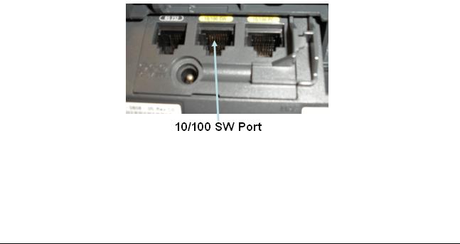
Note: If an inline power switch is not available, skip to Step 3. a. Locate the two RJ-45 ports on the back of the IP phone.
b.What are the names of the two RJ-45 ports? ______________________________________
c.Connect a power cord to the switch that is to provide the inline power. The switch should power on.
25 - 165 IP Telephony v1.0 Lab 2.1.3 |
Copyright © 2005, Cisco Systems, Inc. |
d.Connect a straight-through Ethernet cable from the 10/100 SW port on the IP phone to any 100 MB port on the inline power switch.
e.What indication is shown that the phone is receiving power? _________________________
__________________________________________________________________________
Step 3 Cabling the IP phone to a non-inline power switch
a.Connect power to the non-inline power switch.
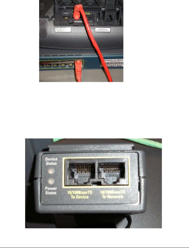
b.In order to connect a Cisco IP phone to a non-inline power switch, a power injector is needed. Look at the power injector and notice the two RJ-45 jacks on one end of the power injector.
26 - 165 IP Telephony v1.0 Lab 2.1.3 |
Copyright © 2005, Cisco Systems, Inc. |
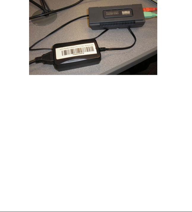
The port on the left labeled 10/100BaseTX to Device is used to connect to the IP phone (via a straight-through cable).The port on the right labeled 10/100BaseTX to Network is used to connect to a non-inline power switch such as a 2950 switch (via a straight-through cable).
c.Connect a straight-through cable from the left power injector port labeled 10/100BaseTX To Device to the IP phone port labeled 10/100 SW.
d.Connect a second straight-through cable from the right power injector port labeled 10/100BaseTX To Network to any non-inline power switch port.
e.At the opposite end of the power injector module there is a cable that goes to the power supply adapter. The opposite end of the power supply adapter requires an AC power cord.
Plug an AC power cord into the AC adapter. Plug the other end of the AC power cord into an AC wall outlet.
f.What indication is shown on the phone that power has been applied?
______________________________________________________________________________
_______________________
27 - 165 IP Telephony v1.0 Lab 2.1.3 |
Copyright © 2005, Cisco Systems, Inc. |

Answers to 2.1.3 Lab
1b. At the time this lab was written, the 2970 was the most powerful 29xx series switch and it does not support inline power for all of its ports.
2b. 10/100 SW and 10/100 PC
2e. The phone starts displaying words on the screen. Also, when power is first applied, the buttons on the bottom start lighting up sequentially.
3f. The phone starts displaying words on the screen. Also, when power is first applied, the buttons on the bottom start lighting up sequentially.
28 - 165 IP Telephony v1.0 Lab 2.1.3 |
Copyright © 2005, Cisco Systems, Inc. |

Lab 2.1.4 Resetting a 7900 Series Cisco IP Phone to Factory Defaults
Objective
•Erase the current configuration from an IP phone
Equipment Requirements
•Cisco IP Phone 79xx series
•Inline power capable switch or non-inline power switch with power injectors
In this lab, the ACME.com Company has decided to deploy CallManager Express (CME) in the enterprise. First, the IP phones must be reset. They were used in a test lab by the network support staff and currently have various configurations. This process should be used when configuring any IP phone that could have been previously configured.
Step 1 Provide power to the switch
a.Cable the Cisco IP phone to an inline power switch using a straight-through cable OR cable the phone (with a straight-through cable) to a power module that connects to a non-inline power switch.
b.Power on the switch.
c.Which method of providing power to the IP phone was chosen? __________________________
29 - 165 IP Telephony v1.0 Lab 2.1.4 |
Copyright © 2005, Cisco Systems, Inc. |

d. What is an advantage of using an in-line power switch? ________________________________
_____________________________________________________________________________
Step 2 Reset the Cisco IP phone
a.On the IP phone press the following keys to unlock the Network Configuration menu: **#. Note: No feedback will be given on the screen.
b.Press the Settings button on the phone. If the phone buttons are unlabelled, it is the button that has a checkmark on the button.
c.Press the number 3 on the keypad to select the Network Configuration option.
d.Using the arrow keys scroll up and down to see the network configuration options. How many options are available? ___________________________________________________________
e.Either scroll to the number 33 options or press the number 33 on the keypad. The Erase Configuration option should now be displayed on the IP phone.
Note: A key to whether or not this works properly is that the symbol of an unlocked lock is beside the words Network Configuration. If the symbol is a lock press the following keys: **#.
f.Press the button located under the Yes option.
g.Press the button located under the Save option.
What message appears on the IP phone screen? ___________________________________
h.Press the button that corresponds to Cancel.
i.Press the Save option.
j.What message appears on the IP phone screen? ___________________________________
30 - 165 IP Telephony v1.0 Lab 2.1.4 |
Copyright © 2005, Cisco Systems, Inc. |
Loading...