


 Loading...
Cisco ICM Software
Supervisor Guide
ICM Software Version 4.5
Corporate Headquarters
Cisco Systems, Inc.
170 West Tasman Drive San Jose, CA 95134-1706 USA http://www.cisco.com Tel: 408 526-4000
800 553-NETS (64387) Fax: 408 526-4100
Customer Order Number: DOC-7811588 =
Text Part Number: 78-11588-01
THE SPECIFICATIONS AND INFORMATION REGARDING THE PRODUCTS IN THIS MANUAL ARE SUBJECT TO CHANGE WITHOUT NOTICE. ALL STATEMENTS, INFORMATION, AND RECOMMENDATIONS IN THIS MANUAL ARE BELIEVED TO BE ACCURATE BUT ARE PRESENTED WITHOUT WARRANTY OF ANY KIND, EXPRESS OR IMPLIED. USERS MUST TAKE FULL RESPONSIBILITY FOR THEIR APPLICATION OF ANY PRODUCTS.
THE SOFTWARE LICENSE AND LIMITED WARRANTY FOR THE ACCOMPANYING PRODUCT ARE SET FORTH IN THE INFORMATION PACKET THAT SHIPPED WITH THE PRODUCT AND ARE INCORPORATED HEREIN BY THIS REFERENCE. IF YOU ARE UNABLE TO LOCATE THE SOFTWARE LICENSE OR LIMITED WARRANTY, CONTACT YOUR CISCO REPRESENTATIVE FOR A COPY.
The following information is for FCC compliance of Class A devices: This equipment has been tested and found to comply with the limits for a Class A digital device, pursuant to part 15 of the FCC rules. These limits are designed to provide reasonable protection against harmful interference when the equipment is operated in a commercial environment. This equipment generates, uses, and can radiate radio-frequency energy and, if not installed and used in accordance with the instruction manual, may cause harmful interference to radio communications. Operation of this equipment in a residential area is likely to cause harmful interference, in which case users will be required to correct the interference at their own expense.
The following information is for FCC compliance of Class B devices: The equipment described in this manual generates and may radiate radio-frequency energy. If it is not installed in accordance with Cisco’s installation instructions, it may cause interference with radio and television reception. This equipment has been tested and found to comply with the limits for a Class B digital device in accordance with the specifications in part 15 of the FCC rules. These specifications are designed to provide reasonable protection against such interference in a residential installation. However, there is no guarantee that interference will not occur in a particular installation.
Modifying the equipment without Cisco’s written authorization may result in the equipment no longer complying with FCC requirements for Class A or Class B digital devices. In that event, your right to use the equipment may be limited by FCC regulations, and you may be required to correct any interference to radio or television communications at your own expense.
You can determine whether your equipment is causing interference by turning it off. If the interference stops, it was probably caused by the Cisco equipment or one of its peripheral devices. If the equipment causes interference to radio or television reception, try to correct the interference by using one or more of the following measures:
•Turn the television or radio antenna until the interference stops.
•Move the equipment to one side or the other of the television or radio.
•Move the equipment farther away from the television or radio.
•Plug the equipment into an outlet that is on a different circuit from the television or radio. (That is, make certain the equipment and the television or radio are on circuits controlled by different circuit breakers or fuses.)
Modifications to this product not authorized by Cisco Systems, Inc. could void the FCC approval and negate your authority to operate the product.
The Cisco implementation of TCP header compression is an adaptation of a program developed by the University of California, Berkeley (UCB) as part of UCB’s public domain version of the UNIX operating system. All rights reserved. Copyright © 1981, Regents of the University of California.
NOTWITHSTANDING ANY OTHER WARRANTY HEREIN, ALL DOCUMENT FILES AND SOFTWARE OF THESE SUPPLIERS ARE PROVIDED “AS IS” WITH ALL FAULTS. CISCO AND THE ABOVE-NAMED SUPPLIERS DISCLAIM ALL WARRANTIES, EXPRESSED OR IMPLIED, INCLUDING, WITHOUT LIMITATION, THOSE OF MERCHANTABILITY, FITNESS FOR A PARTICULAR PURPOSE AND NONINFRINGEMENT OR ARISING FROM A COURSE OF DEALING, USAGE, OR TRADE PRACTICE.
IN NO EVENT SHALL CISCO OR ITS SUPPLIERS BE LIABLE FOR ANY INDIRECT, SPECIAL, CONSEQUENTIAL, OR INCIDENTAL DAMAGES, INCLUDING, WITHOUT LIMITATION, LOST PROFITS OR LOSS OR DAMAGE TO DATA ARISING OUT OF THE USE OR INABILITY TO USE THIS MANUAL, EVEN IF CISCO OR ITS SUPPLIERS HAVE BEEN ADVISED OF THE POSSIBILITY OF SUCH DAMAGES.
Access Registrar, AccessPath, Are You Ready, ATM Director, Browse with Me, CCDA, CCDE, CCDP, CCIE, CCNA, CCNP, CCSI, CD-PAC, CiscoLink, the Cisco NetWorks logo, the Cisco Powered Network logo, Cisco Systems Networking Academy, Fast Step, FireRunner, Follow Me Browsing, FormShare, GigaStack, IGX, Intelligence in the Optical Core, Internet Quotient, IP/VC, iQ Breakthrough, iQ Expertise, iQ FastTrack, iQuick Study, iQ Readiness Scorecard, The iQ Logo, Kernel Proxy, MGX, Natural Network Viewer, Network Registrar, the Networkers logo, Packet, PIX, Point and Click Internetworking, Policy Builder, RateMUX, ReyMaster, ReyView, ScriptShare, Secure Script, Shop with Me, SlideCast, SMARTnet, SVX, TrafficDirector, TransPath, VlanDirector, Voice LAN, Wavelength Router, Workgroup Director, and Workgroup Stack are trademarks of Cisco Systems, Inc.; Changing the Way We Work, Live, Play, and Learn, Empowering the Internet Generation, are service marks of Cisco Systems, Inc.; and Aironet, ASIST, BPX, Catalyst, Cisco, the Cisco Certified Internetwork Expert Logo, Cisco IOS, the Cisco IOS logo, Cisco Press, Cisco Systems, Cisco Systems Capital, the Cisco Systems logo, Collision Free, Enterprise/Solver, EtherChannel, EtherSwitch, FastHub, FastLink, FastPAD, IOS, IP/TV, IPX, LightStream, LightSwitch, MICA, NetRanger, Post-Routing, Pre-Routing, Registrar, StrataView Plus, Stratm, SwitchProbe, TeleRouter, are registered trademarks of Cisco Systems, Inc. or its affiliates in the U.S. and certain other countries.
All other brands, names, or trademarks mentioned in this document/website are the property of their respective owners. The use of the word partner does not imply a partnership relationship between Cisco and any of its resellers. (0008R)
Cisco ICM Software Supervisor Guide
Copyright © 1995 - 2001 Cisco Systems, Inc.
All rights reserved.

iii
Contents
Preface ........................................................................................ |
xiii |
Purpose ................................................................................................... |
xiii |
Audience.................................................................................................. |
xiii |
Organization ............................................................................................ |
xiii |
Typographic Conventions....................................................................... |
xiv |
Other Publications ................................................................................... |
xv |
1. Overview |
................................................................................. |
17 |
1.1. What is the Intelligent CallRouter? .................................................... |
18 |
|
1.1.1. .......................................................Where Does the ICR Fit In? |
19 |
|
1.1.2. ................................................................................ |
Call Routing |
20 |
1.1.3. ................................................................................ |
Pre - Routing |
21 |
1.1.4. ............................................................................... |
Post - Routing |
21 |
1.1.5. ............................................................................ |
Enterprise CTI |
21 |
1.1.6. .................................................................... |
Call Routing Scripts |
22 |
1.1.7. ........................................................... |
Reporting and Monitoring |
22 |
1.1.8. ............................................................................... |
Network ICR |
23 |
1.2. The Call ...................................................................Center Enterprise |
23 |
|
1.2.1. ..........................................................Services and Skill Groups |
24 |
|
1.2.2. ...........................................................Agents and Agent Teams |
27 |
|
1.2.3. ..............................................Trunk and Network Trunk Groups |
27 |
|
1.2.4. ............................................................................ |
Service Arrays |
28 |
1.2.5. ........................................................................................ |
Routes |
29 |
1.2.6. .....................................................Other Parts of the Enterprise |
30 |
|
1.3. Peripheral .........................................................-Specific Terminology |
32 |
|
2. The Admin Workstation ........................................................ |
37 |
|
2.1. The GEOTEL Admin Workstation Group.............................................. |
38 |
|
2.2. Distributor and Client Admin Workstations....................................... |
39 |
|
2.2.1. |
Real-Time and Historical Data ................................................... |
40 |
2.2.2. |
Historical Database Server (HDS) ............................................. |
40 |
Contents

iv Contents
2.2.3. |
Monitor-Only AW ....................................................................... |
40 |
2.2.4. |
Admin Workstation Users .......................................................... |
41 |
2.2.5. |
Open Database Architecture ..................................................... |
41 |
2.3. Monitor ICR Reporting ......................................................................... |
41 |
|
2.3.1. Enterprise and Peripheral Reporting ......................................... |
42 |
|
2.3.2. |
Agent Reporting ......................................................................... |
43 |
2.4. Monitor ICR Reporting Scenario......................................................... |
44 |
|
2.4.1. |
Viewing Multiple Reports ........................................................... |
44 |
2.4.2. |
Analyzing the Data..................................................................... |
45 |
2.4.3. |
Correcting the Situation ............................................................. |
46 |
2.4.4. Monitor ICR Reporting Terms.................................................... |
46 |
|
2.5. Web View............................................................................................... |
47 |
|
3. Creating a Report................................................................... |
49 |
|
3.1. The Report Example............................................................................. |
50 |
|
3.2. Starting Monitor ICR ............................................................................ |
52 |
|
3.2.1. |
Controller Time .......................................................................... |
52 |
3.3. Setting Up the Template Launcher..................................................... |
53 |
|
3.4. Launching the Report .......................................................................... |
56 |
|
3.4.1. What the Report Shows............................................................. |
58 |
|
3.4.2. |
The Status Bar ........................................................................... |
59 |
3.5. Retrieving the Latest Historical Data ................................................. |
59 |
|
3.6. Printing the Report............................................................................... |
59 |
|
3.7. Saving the Report................................................................................. |
59 |
|
3.8. Opening the Report.............................................................................. |
61 |
|
3.9. Setting Thresholds............................................................................... |
61 |
|
3.10. Adding Drill-Downs ............................................................................ |
64 |
|
3.11. Saving Your Workspace .................................................................... |
67 |
|

|
Contents |
v |
4. Reporting Basics ................................................................... |
69 |
|
4.1. The GEOTEL Admin Workstation Group.............................................. |
70 |
|
4.2. Starting Monitor ICR ............................................................................. |
71 |
|
4.2.1. |
Toolbar Options.......................................................................... |
72 |
4.2.2. |
On-Line Help .............................................................................. |
73 |
4.2.3. |
Controller Time........................................................................... |
74 |
4.2.4. |
Command Prompt Startup Options ............................................ |
75 |
4.3. Working with the Template Launcher................................................. |
75 |
|
4.3.1. |
Category and Scope................................................................... |
77 |
4.3.2. |
Date and Time............................................................................ |
80 |
4.3.3. |
Items........................................................................................... |
83 |
4.3.4. |
Templates................................................................................... |
84 |
4.3.5. |
Launching Templates ................................................................. |
85 |
4.4. Working with Reports........................................................................... |
86 |
|
4.4.1. |
Saving Report Definitions........................................................... |
86 |
4.4.2. |
Singleand Multiple-Component Reports .................................. |
88 |
4.4.3. |
Shuffle Mode .............................................................................. |
90 |
4.4.4. |
Working with Several Reports.................................................... |
92 |
4.4.5. |
Status Bar................................................................................... |
93 |
4.4.6. |
Retrieving Historical Data........................................................... |
93 |
4.4.7. |
Pausing the Screen Refresh ...................................................... |
93 |
4.5. Reconnecting to the Central Database............................................... |
94 |
|
4.6. Printer Setup ......................................................................................... |
94 |
|
4.7. Printing Reports.................................................................................... |
96 |
|
4.7.1. |
Printing Multiple-Component Reports ........................................ |
96 |
4.8. Opening Saved Reports ....................................................................... |
96 |
|
4.9. File Association .................................................................................... |
97 |
|
4.10. Saving Your Workspace..................................................................... |
98 |
|
4.11. Modifying Report Definitions............................................................. |
99 |
|
4.12. Deleting Report Definitions ............................................................. |
100 |
|
4.13. Exporting Report Data...................................................................... |
101 |
|
4.14. Setting Workstation Preferences .................................................... |
102 |
|
4.14.1. Event Feed Warning................................................................. |
105 |
|
4.15. User Information ............................................................................... |
105 |
|
Contents

vi Contents
5. Setting Thresholds and Drill-Downs .................................. |
107 |
|
5.1. Setting Thresholds in Reports .......................................................... |
108 |
|
5.1.1. Setting Thresholds in Multiple-Component Reports ................ |
109 |
|
5.1.2. |
Saving Threshold Settings....................................................... |
110 |
5.2. Using Drill-Downs in Reports............................................................ |
110 |
|
5.2.1. |
Drill-Down Hierarchy................................................................ |
110 |
5.2.2. |
Adding Drill-Downs .................................................................. |
111 |
5.2.3. |
Saving Drill-Down Assignments............................................... |
113 |
5.2.4. |
Invoking Drill-Downs ................................................................ |
113 |
5.2.5. |
Saving Drill-Downs as Separate Reports ................................ |
115 |
6. Scheduling Reports ............................................................. |
117 |
|
6.1. ICR Job Scheduler ............................................................................. |
118 |
|
6.1.1. |
Job Scheduler Printing Requirements ..................................... |
118 |
6.1.2. Scheduling Reports to Print ..................................................... |
119 |
|
6.1.3. |
Changing Scheduled Jobs....................................................... |
122 |
6.1.4. |
Deleting Scheduled Jobs ......................................................... |
123 |
6.1.5. Inspecting the Job Scheduler Log ........................................... |
123 |
|
6.1.6. |
Closing the ICR Job Scheduler................................................ |
124 |
7. Available Data ...................................................................... |
125 |
|
7.1. Skill Group Data ................................................................................. |
126 |
|
7.1.1. Skill Group Agent Data ............................................................ |
126 |
|
7.1.2. |
Percent Utilization.................................................................... |
127 |
7.1.3. |
Call Handling............................................................................ |
127 |
7.2. Agent Data........................................................................................... |
128 |
|
7.2.1. |
Agent Tables............................................................................ |
128 |
7.2.2. |
Agent Status ............................................................................ |
129 |
7.2.3. |
Agent Activity ........................................................................... |
129 |
7.2.4. |
Agent Performance.................................................................. |
130 |
7.3. Agent States and Time Allocations .................................................. |
132 |
|
7.3.1. ICR Agent State Terminology .................................................. |
134 |
|
7.3.2. ICR Agent State Mapping To Peripherals ............................... |
137 |
|
7.4. Service Data........................................................................................ |
141 |
|
7.4.1. |
Call Counts .............................................................................. |
141 |
7.4.2. |
Service Level ........................................................................... |
142 |
7.4.3. |
Queues and Delays ................................................................. |
144 |
7.4.4. |
Agent Time Allocations ............................................................ |
145 |
7.5. Enterprise Data................................................................................... |
145 |
|
7.5.1. |
Enterprise Calculations............................................................ |
146 |

Contents |
vii |
7.6. Trunk Group Data ............................................................................... |
146 |
7.7. Network Trunk Group Data ................................................................ |
147 |
7.8. Service Array Data .............................................................................. |
147 |
7.9. Route Data ........................................................................................... |
148 |
7.9.1. Service Level............................................................................ |
149 |
7.10. Peripheral Data.................................................................................. |
149 |
7.11. Application Gateway Data................................................................ |
150 |
7.12. Call Type Data ................................................................................... |
151 |
7.13. Routing Client Data .......................................................................... |
151 |
7.14. Schedule Import Data....................................................................... |
152 |
8. Template Reference ............................................................ |
153 |
8.1. Real-Time and Historical Templates ................................................. |
154 |
agteam01_agent_status_by_position ................................................... |
155 |
agteam02_agent_status_by_skillgroup................................................. |
156 |
agteam03_logout_status_by_team ....................................................... |
157 |
agteam04_daily_agent_activity............................................................. |
158 |
agteam05_agent_daily_perf.................................................................. |
160 |
agtper01_agent_status_by_position ..................................................... |
163 |
agtper02_agent_status_by_skillgroup .................................................. |
164 |
agtper03_logout_status_by_peripheral................................................. |
165 |
agtper04_daily_agent_activity............................................................... |
166 |
agtper05_agent_daily_perf ................................................................... |
168 |
agtskg01_agent_status_by_position..................................................... |
171 |
agtskg02_agent_status_by_skillgroup .................................................. |
172 |
agtskg03_logout_status_by_skillgroup ................................................. |
173 |
agtskg04_daily_agent_activity .............................................................. |
174 |
agtskg05_agent_daily_perf ................................................................... |
176 |
apgate11_status_by_half_hour............................................................. |
179 |
caltyp01_status_grid ............................................................................. |
180 |
caltyp02_count_graph ........................................................................... |
181 |
entskg01_status_#_graph ..................................................................... |
182 |
entskg02_status_grid ............................................................................ |
183 |
entskg03_status_%_graph.................................................................... |
185 |
entskg04_status_grid_to5 ..................................................................... |
186 |
entskg05_utilization_graph.................................................................... |
188 |
entskg06_halfhour_aht_grid.................................................................. |
189 |
entskg07_daily_aht_grid ....................................................................... |
191 |
entskg08_halfhour_perform_grid .......................................................... |
193 |
Contents

viii Contents
entskg09_normalized_agt_state........................................................... |
195 |
entsvc01_queue_delay_status ............................................................. |
196 |
entsvc02_calls_status........................................................................... |
197 |
entsvc03_effect_of_aban_on_servicelevel........................................... |
198 |
entsvc04_calls_trend_analysis ............................................................. |
199 |
entsvc05_calls_offered_half_pie .......................................................... |
200 |
entsvc06_serv_level_monitor_graph .................................................... |
201 |
entsvc07_now_to5_grid........................................................................ |
202 |
entsvc08_gate_realtime_status_grid .................................................... |
204 |
entsvc09_svc_array_now_to5_grid ...................................................... |
206 |
entsvc11_calls_analysis_daywise ........................................................ |
208 |
entsvc12_calls_analysis_half_hour ...................................................... |
209 |
entsvc13_calls_offered_daywise_graph............................................... |
211 |
entsvc14_calls_handled_daywise_graph ............................................. |
212 |
entsvc15_calls_abandoned_daywise_graph........................................ |
213 |
entsvc16_calls_history_daywise_graph ............................................... |
214 |
entsvc17_calls_offered_half_hour ........................................................ |
215 |
entsvc18_gate_half_hourly_status_grid ............................................... |
216 |
nettrk01_status_grid ............................................................................. |
218 |
nettrk02_grid_last_half_hour ................................................................ |
219 |
nettrk12_grid_half_hour........................................................................ |
220 |
peragt01_agent_status_by_position..................................................... |
221 |
peragt02_agent_status_by_skillgroup .................................................. |
222 |
peragt03_logout_status_by_agent ....................................................... |
223 |
peragt04_daily_agent_activity .............................................................. |
224 |
peragt05_agent_daily_perf ................................................................... |
226 |
peragt06_daily_agent_detail................................................................. |
229 |
periph01_peripheral_status_report....................................................... |
230 |
periph02_galaxy_software_status ........................................................ |
231 |
periph03_galaxy_hardware_status....................................................... |
232 |
perskg01_status_#_graph .................................................................... |
233 |
perskg02_status_grid............................................................................ |
234 |
perskg03_status_%_graph ................................................................... |
236 |
perskg04_status_grid_to5 .................................................................... |
237 |
perskg05_utilization_graph................................................................... |
239 |
perskg06_halfhour_aht_grid ................................................................. |
240 |
perskg07_daily_aht_grid....................................................................... |
242 |
perskg08_halfhour_perform_grid.......................................................... |
244 |
perskg09_normalized_agt_state........................................................... |
246 |
perskg10_forecast_agents_status_grid................................................ |
247 |
persvc01_queue_delay_status ............................................................. |
248 |
persvc02_calls_status........................................................................... |
249 |
persvc03_effect_of_aban_on_servicelevel .......................................... |
250 |
persvc04_calls_trend_analysis............................................................. |
251 |
persvc05_calls_offered_half_pie .......................................................... |
252 |
persvc06_serv_level_monitor_graph.................................................... |
253 |
persvc07_now_to5_grid........................................................................ |
254 |
persvc08_gate_realtime_status_grid.................................................... |
256 |
persvc09_forecast_aht_offer_grid ........................................................ |
258 |
persvc11_calls_analysis_daywise ........................................................ |
259 |

Contents |
ix |
persvc12_calls_analysis_half_hour ...................................................... |
261 |
persvc13_calls_offered_daywise_graph ............................................... |
263 |
persvc14_calls_handled_daywise_graph ............................................. |
264 |
persvc15_calls_abandoned_daywise_graph ........................................ |
265 |
persvc16_calls_history_daywise_graph................................................ |
266 |
persvc17_calls_offered_half_hour ........................................................ |
267 |
persvc18_gate_half_hourly_status_grid ............................................... |
268 |
routes01_queue_delay_status .............................................................. |
270 |
routes02_calls_status............................................................................ |
271 |
routes03_effect_of_aban_on_servicelevel............................................ |
272 |
routes04_calls_trend_analysis .............................................................. |
273 |
routes05_calls_offered_half_pie ........................................................... |
274 |
routes06_serv_level_monitor_graph..................................................... |
275 |
routes07_now_to5_grid......................................................................... |
276 |
routes11_calls_analysis_daywise ......................................................... |
278 |
routes12_calls_analysis_half_hour ....................................................... |
280 |
rtecli11_status_by_five_minutes ........................................................... |
282 |
schimp01_name_time_numbers ........................................................... |
283 |
trkgrp01_alltrunkbusy_graph................................................................. |
284 |
trkgrp02_idle_inservice_status.............................................................. |
285 |
trkgrp03_trunkgroup_status_grid .......................................................... |
286 |
trkgrp11_trunkgroup_performance_grid................................................ |
287 |
Glossary..................................................................................... |
289 |
Index .......................................................................................... |
319 |
Contents

x Contents
Figures |
|
Figure 1: ICR Call Routing.................................................................................. |
18 |
Figure 2: Intelligent CallRouter Overview ........................................................... |
19 |
Figure 3: ICR Call Flow Diagram ........................................................................ |
20 |
Figure 4: Service and Skill Group Hierarchy....................................................... |
24 |
Figure 5: Enterprise and Peripheral Services ..................................................... |
25 |
Figure 6: Enterprise and Peripheral Skill Groups ............................................... |
26 |
Figure 7: Agent Hierarchy................................................................................... |
27 |
Figure 8: Network and Peripheral Trunk Groups................................................ |
28 |
Figure 9: Service Arrays ..................................................................................... |
29 |
Figure 10: Routes ............................................................................................... |
30 |
Figure 11: Enterprise and Peripheral Reporting ................................................. |
42 |
Figure 12: Sample Report................................................................................... |
45 |
Figure 13: Web View Report............................................................................... |
47 |
Figure 14: Enterprise Service Calculation Examples ....................................... |
146 |
Contents |
xi |
Tables |
|
Table 1: Aspect, Lucent, and Nortel—ICR Terminology Mapping ...................... |
33 |
Table 2: Rockwell and Siemens—ICR Terminology Mapping ............................ |
34 |
Table 3: Alcatel, NEC, and Ericsson—ICR Terminology Mapping ..................... |
34 |
Table 4: Features Not Supported for Specific Peripherals.................................. |
35 |
Table 5: Agent Report Types .............................................................................. |
43 |
Table 6: Monitor ICR Toolbar .............................................................................. |
72 |
Table 7: Default ICR Subdirectories.................................................................... |
87 |
Table 8: File Format Options............................................................................. |
102 |
Table 9: Drill-Down Hierarchy ........................................................................... |
111 |
Table 10: Agent States and Time Allocations ................................................... |
135 |
Table 11: Agent State Terminology—Aspect, Lucent, and Nortel .................... |
137 |
Table 12: Agent State Terminology—Rockwell and Siemens .......................... |
139 |
Table 13: Agent State Terminology—Alcatel, NEC, and Ericsson.................... |
140 |
Contents

xii Contents

xiii
Preface
Preface
Purpose
This manual describes how to monitor enterprise call center activity with the real-time and historical reporting features of the GEOTEL Intelligent CallRouter (ICR).
Audience
This document is intended for the Intelligent CallRouter supervisor. The supervisor has an understanding of call center management and the specific types of data that are used to report on call center activity and resources.
This document assumes that you have some familiarity with Microsoft® Windows™ applications and common tasks such as moving and resizing windows and using a mouse.
Organization
Chapter 1, “Overview”
Introduces the Intelligent CallRouter and the ICR call center enterprise.
Chapter 2, “The Admin Workstation”
Introduces the Admin Workstation (AW) with a special emphasis on call center reporting and the Monitor ICR reporting application.
Chapter 3, “Creating a Report”
Guides you through the process of creating a simple report using the predefined report templates of Monitor ICR.
Chapter 4, “Reporting Basics”
Describes how to use the basic features of Monitor ICR.
Chapter 5, “Setting Thresholds and Drill-Downs”
Describes how to set threshold values and drill-down templates in
Monitor ICR reports.

xiv Preface
Chapter 6, “ Scheduling Reports”
Describes how to schedule reports to print automatically by using the ICR Job Scheduler tool.
Chapter 7, “Available Data”
Describes the most commonly used data available in the ICR databases.
Chapter 8, “Template Reference”
Documents the predefined report templates that come with Monitor ICR.
Typographic Conventions
This manual uses the following conventions:
Boldface type is used for emphasis; for example:
Real-time information is not stored in the central database.
Italic type indicates one of the following:
•A newly introduced term; for example:
A skill group is a collection of agents who share similar skills.
•A generic syntax item that you must replace with a specific value; for example:
IF (condition, true-value, false-value)
•A title of a publication; for example:
For more information, see the Intelligent CallRouter Database
Schema Handbook.
Sans serif type with small caps represents keys on your keyboard; for example:
Press the SHIFT key to select a range of items.
An arrow (→) indicates an item from a pull-down menu. For example, the Save command from the File menu is referenced as File→Save.
Text you must type is shown in a sans serif type. For example:
Date and Time

Preface xv
Other Publications
•Intelligent CallRouter Custom Screen Builder Tutorial
•Intelligent CallRouter Database Schema Handbook
•Intelligent CallRouter Installation Guide
•Intelligent CallRouter Planning Guide
•Intelligent CallRouter Product Description
•Intelligent CallRouter Quick Start Guide
•Intelligent CallRouter Supervisor Guide
•Intelligent CallRouter System Manager Guide
•GEOTEL•Web View Administrator Guide
For information about the GEOTEL• Network ICR product, see the following documents:
•Network ICR Product Description
•Network ICR User Guide
Preface

xvi Preface

17
1. Overview
The GEOTEL Intelligent CallRouter (ICR) improves the level of customer service offered by geographically distributed call centers. The Intelligent CallRouter’s main function is to route toll-free calls to the most appropriate agent or answering resource available. The system also provides a set of computer telephony integration (CTI), reporting, monitoring, and scheduling tools that help you to manage a distributed call center enterprise.
This chapter provides an overview of the Intelligent CallRouter and describes its role in a multiple call center environment.
Overview .1

18 Overview
1.1. What is the Intelligent CallRouter?
The Intelligent CallRouter (ICR) is a software-based call processing system that provides call-by-call routing to geographically distributed call centers. The ICR links agents from multiple call centers to create a virtual call center.
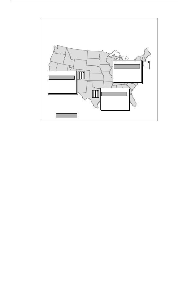
In the virtual call center model, agents from distributed call centers can be grouped logically according to their areas of expertise. For example, a financial company might have call centers in several cities across the country. Each call center has groups of agents organized into skill groups.
The agents in these skill groups are trained to handle certain types of calls. Basic calls can be routed to skill groups that are trained to provide general services. Callers who have more complicated transactions can be routed to more specialized skill groups.
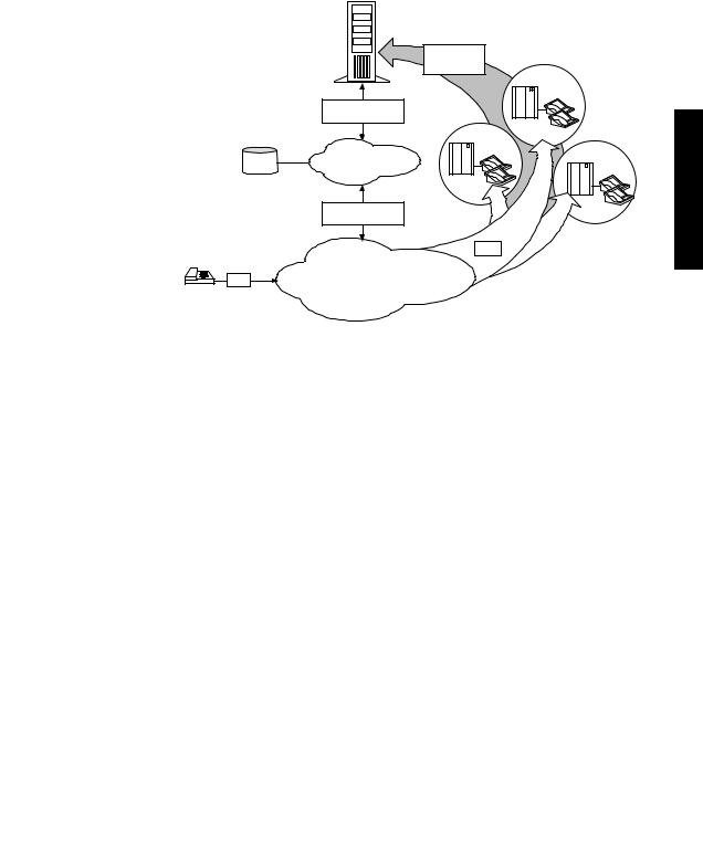
Figure 1 shows how calls are routed to the best available agents in the call center enterprise.
Figure 1: ICR Call Routing
What happens if several callers require the services of a specialized agent? For example, you might have several callers who need the assistance of a financial planner. This type of specialized agent may not always be immediately available at one call center. However, since the Intelligent CallRouter is aware of the status of the entire enterprise, it can quickly find financial planners at other call centers and route the calls accordingly.
What is the Intelligent CallRouter? |
19 |
1.1.1.Where Does the ICR Fit In?
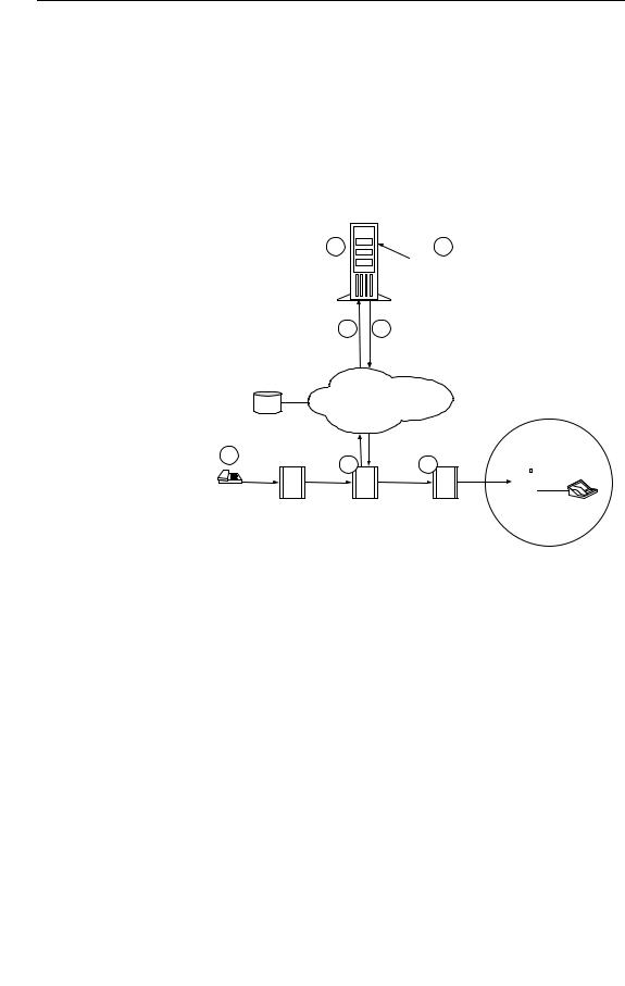
The Intelligent CallRouter works directly with call centers and the interexchange carrier (IXC) that supplies the toll-free service. The IXC is a long-distance telephone company that offers toll-free call routing services. Figure 2 shows how the Intelligent CallRouter operates between the IXC network and distributed call centers.
|
|
Intelligent |
|
|
|
CallRouter |
Agent, Queue, |
|
|
|
|
|
|
|
CTI data |
|
|
Call Associated |
|
|
|
Data |
|
|
SCP |
Signaling Network |
|
Service Control Point |
|
||
|
|
Call Associated |
|
|
|
Data |
|
|
|
|
Calls |
|
|
Public |
|
|
Calls |
Switched Network |
|
Toll-Free |
Callers |
|
|
ACD, PBX, |
|
|
VRU |
|
|
Agent |
Call |
Centers |
Groups |
|
|
Overview .1
Figure 2: Intelligent CallRouter Overview
The IXC signaling network controls how calls are routed in the public switched network. In addition to connecting to the signaling network, the ICR has data connections to each call center peripheral. A peripheral may be an Automatic Call Distributor (ACD), Private Branch Exchange (PBX), or Voice Response Unit (VRU). The data connections to each peripheral provide the ICR with real-time data on agent group and call activity.
The ICR has two main functions in the call center enterprise: routing calls and collecting management information. The management information is used to make informed decisions on where to route calls. It is also used to monitor and report on call center performance. In a GEOTEL•Enterprise CTI environment, management data can also used in a variety of integrated desktop and server CTI applications.
20Overview
1.1.2.Call Routing
A typical ICR-routed call goes through the following stages. Figure 3 illustrates these stages in detail.
•The Intelligent CallRouter is constantly receiving data from call centers on agent availability, queue status, and call handling performance.
ô A caller dials the toll-free number.
í The Local Exchange Carrier (LEC) passes the call to the IXC.
Intelligent CallRouter
ICR
5 |
1 |
5RXWLQJ 5HTXHVW ,QFOXGHV
'LDOHG 1XPEHU
&DOOLQJ /LQH ,'
&DOOHU (QWHUHG 'LJLWV ;;
SCP
$JHQW DQG 4XHXH 'DWD IURP 5HPRWH &DOO &HQWHUV
4 |
6 5RXWLQJ /DEHO 5HWXUQHG |
BT Signaling
Network
2 |
3 |
7 |
&DOOHU V 1XPEHU |
||
|
|
|
&DOOHU |
|
|
/RFDO ([FKDQJH |
%7 6ZLWFK |
%7 6ZLWFK |
|
|
|
7UXQN *US |
||||||
'1,6 |
-RKQ - |
|||||
|
|
|
|
|
|
|
|
|
|
|
|
|
6NLOO *URXS |
|
|
|
|
|
|
|
&DPEULGJH &DOO &HQWHU $&'
&DOO &HQWHU 6LWH
Figure 3: ICR Call Flow Diagram
÷The IXC signaling network sends call information from its computer (the Service Control Point (SCP)) to the ICR in the form of a routing request.
ûThe ICR, using the information from the IXC routing request and the data it has been receiving from call centers, determines the best agent group based on skills, current agent availability, and queue status.
ø The ICR returns a routing label (destination) for the call to the IXC.
ùThe IXC then connects the call to the ACD where an appropriate agent is located.
What is the Intelligent CallRouter? |
21 |
1.1.3.Pre-Routing
The Intelligent CallRouter uses Pre-Routing® to ensure that incoming calls reach the appropriate agent resource the first time. In Pre-Routing, the ICR executes routing decisions before the call terminates at a call center.
As shown in Figure 3, every time a caller dials the toll-free number, the IXC passes a routing request through the signaling network to the Intelligent CallRouter. The interexchange carrier acts as a routing client, while the Intelligent CallRouter acts as the routing server.
The IXC routing request includes information about the call such as
•Number dialed.
•Calling Line ID (CLID) or Automatic Number Identification (ANI).
•Caller Entered Digits (CED).
The final routing decision, or the call’s destination, is contained in a routing label which the ICR returns to the interexchange carrier. The carrier is then responsible for connecting the call and maintaining the voice path.
1.1.4.Post-Routing
Optionally, the ICR can perform the same routing functions used in
Pre-Routing for transfers and internal calls (that is, for calls originating at a call center or another agent location). The ICR uses Post-Routing® to make these “secondary” routing decisions. Post- Routing also lets you implement intelligent transfer applications in which calls are routed between agents and VRUs. Post-Routing ensures that subsequent call transactions are routed in a timely manner to an appropriate resource.
In Post-Routing calls, the ICR uses the same routing scripts and call processing as it does in Pre-Routing calls. The difference is that the peripheral (ACD, PBX, or VRU) generates the routing request rather than the IXC. The Intelligent CallRouter processes the routing request, returns a destination address (routing label), and then directs the peripheral to send the call to the best resource available.
1.1.5.Enterprise CTI
As an enterprise call routing system, the ICR collects data from different systems and telecommunications environments throughout the call center enterprise. Often these systems are implemented on
heterogeneous hardware and software platforms and distributed across multiple sites. GEOTEL•Enterprise CTI gathers enterprise call and
transaction data from these dissimilar systems and makes it available to agent desktop and CTI server applications.
Overview .1

22 Overview
See also: For more information on Enterprise CTI, see the Intelligent CallRouter
Product Description.
1.1.6.Call Routing Scripts
To determine the best destination for a call, the ICR processes routing requests through call routing scripts. A routing script is a graphical, flowchart-like diagram that specifies how to route a call. A script usually has several branches that can be followed depending on current conditions at the call centers.
In order to make a routing decision, the script uses the information contained in the routing request along with real-time information on the status of resources at each call center. The system manager typically defines a number of routing scripts to use in the ICR system.
Scripts can be scheduled as required to route calls among call centers based on the type of service the caller needs, the time of day the call is being placed, and where suitably qualified agents are available to handle the call.
See also: For more information on the routing scripts, see the Intelligent CallRouter System Manager Guide.
1.1.7.Reporting and Monitoring
The ICR uses real-time, near real-time, and historical data on agent and call center status to make its routing decisions. To make the best routing decision possible, the ICR constantly collects information about agent activity at each call center, such as:
•Current agent state
•Logon duration
•Number of agents available
•Number of agents talking
•The time agents spend in particular call handling states
The ICR also collects information about calls coming into the call centers, such as
•Number of calls in progress
•Number of calls handled and finished
•How calls were routed
•How long callers were on hold

The Call Center Enterprise |
23 |
|
Although this management data is essential to call routing, it is also |
|
|
important for monitoring and reporting on agent and agent group |
|
|
performance. The ICR stores the management data in industry-standard |
|
|
historical and real-time relational databases. |
|
|
The Intelligent CallRouter provides many ways for you to analyze |
|
|
trends and gauge service levels using real-time and historical |
|
|
management data. The main ICR reporting tool, called Monitor ICR, |
|
|
allows you to generate many types of reports on agent and call activity. |
|
|
Monitor ICR is described in more detail later in this chapter. |
|
|
1.1.8. Network ICR |
|
|
GEOTEL• Network ICR is the carrier-class version of the Intelligent |
|
|
CallRouter. It allows a network service provider to offer virtual call |
|
|
center services to its customers. The Network ICR functions much like a |
|
|
Service Control Point (SCP) by distributing incoming calls to individual |
.1 |
|
network service customers based on the number dialed, the call’s point |
|
Overview |
of origin, and caller-entered digits. |
|
|
|
|
|
The Network ICR product uses a two-tiered architecture in which one ICR passes route requests to a second ICR. The first ICR, called the Network ICR or NICR, typically receives routing requests from a carrier network. The NICR can either return a label itself or pass the route request to a second ICR, called the Customer ICR or CICR.
Each CICR can processes all calls for one or more customers. The CICR receives the route request, runs its own routing scripts to determine the destination for the call, and returns a routing label to the NICR. The NICR then returns the label to the original carrier network. This architecture lets a service provider perform simple routing (within the NICR) for some customers while providing full ICR functionality (in a CICR) for other customers.
See also: For more information about Network ICR, see the Network ICR Product Description.
1.2. The Call Center Enterprise
An Intelligent CallRouter treats a customer’s multiple distributed call centers as a single enterprise. You can think of the call center enterprise as an entire company or agency that spans many call centers. The enterprise typically includes all call centers served by an ICR.
You can create different organizational entities within a call center enterprise. For example, you might organize distributed groups of agents into a shared resource pool that spans call centers. You might also create entities that are tied to specific peripherals. The term peripheral refers to the individual switch (ACD, PBX, or VRU) that distributes incoming calls at each call center.
24 Overview
From a reporting perspective, you can view agent and call routing statistics on an enterprise-wide or peripheral-by-peripheral basis. Enterprise reporting gives you a view of performance across the entire call center enterprise. Peripheral reporting focuses your reports on specific areas of the call center enterprise.
To become more familiar with the ICR call center enterprise, it might help to review the types of organizational entities you can define.
See also: Table 1, later in this chapter, provides information on how ICR call center terms map to the terms used by ACD vendors.
1.2.1.Services and Skill Groups
A service is a particular type of call processing that the caller requires. In most cases, a service can be thought of as a certain type of call. For example, in a software company’s call center, callers who have questions about installing software might be directed to the Technical Support service.
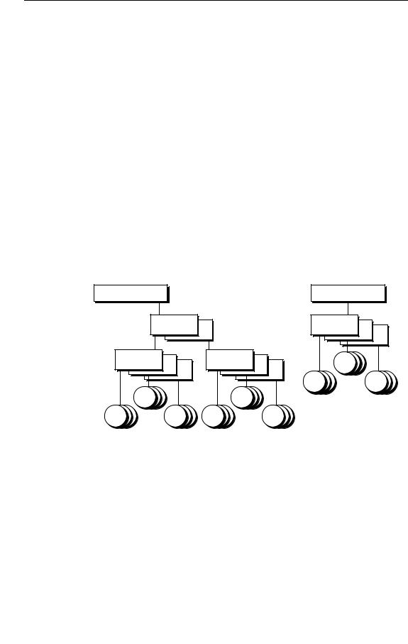
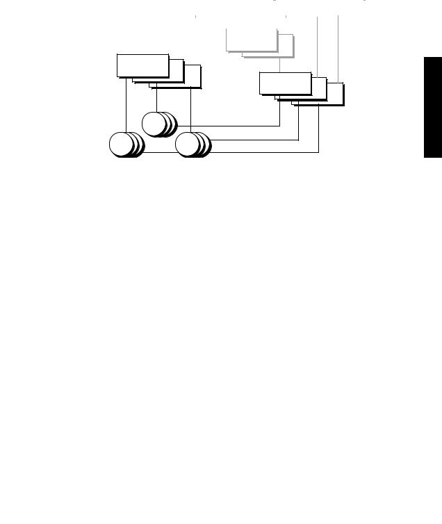
A skill group, on the other hand, is a set of agents who handle similar types of calls or have a common set of skills. A skill group might contain agents who are able to handle a particular type of call (for example, calls from customers who speak Spanish). Figure 4 shows the hierarchy of services and skill groups within a call center enterprise.
Enterprise Service
Enterprise Skill Group
|
Peripheral |
|
Peripheral |
|
|
Services |
|
Skill Groups |
|
Peripheral |
|
Peripheral |
Agents |
|
Skill Groups |
|
Skill Groups |
|
|
|
|
|
Agents |
Agents |
Agents |
|
Agents |
|
|
Agents |
Agents |
Agents |
Agents |
|
Figure 4: Service and Skill Group Hierarchy
As shown in Figure 4, you can group services and skill groups to create enterprise services and enterprise skill groups. These are simply collections of services and skill groups that span call centers.
A peripheral service is a service that is tied to a specific ACD or PBX. You might have several Sales peripheral services. Each Sales peripheral service is tied to, or associated with, a specific peripheral somewhere in the call center enterprise. The Sales services can be logically grouped
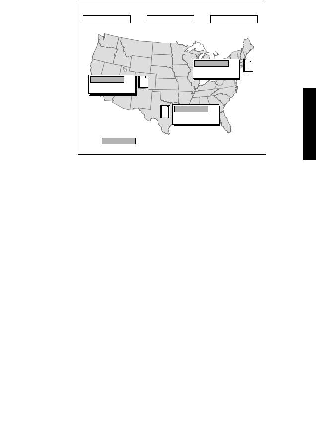
The Call Center Enterprise |
25 |
across peripherals to form an enterprise Sales service. Figure 5 shows the relationship between enterprise and peripheral services.
|
Enterprise |
Services |
|
|
|
|
Sales |
Technical Support |
Information Services |
|
|||
|
Peripheral |
Services |
|
|
|
|
|
|
|
Boston Sales |
|
|
|
|
|
|
Boston |
Tech. Support |
|
|
|
|
|
Boston Info. Services |
ACD |
|
|
Denver Sales |
|
|
|
|
|
|
|
|
|
|
|
|
|
Denver Tech. Support |
|
|
|
|
|
|
Denver Info. Services |
ACD |
|
|
|
|
|
|
|
Dallas |
Sales |
|
|
1 |
|
|
Dallas |
Tech. Support |
|
. |
|
|
|
|
Overview |
|||
|
ACD |
Dallas |
Info. Services |
|
||
|
|
|
||||
|
These peripheral services are logically combined to form the |
|
|
|||
|
enterprise service, |
Sales. |
|
|
|
|
Figure 5: Enterprise and Peripheral Services
Peripheral services typically include a number of skill groups, each of which can be set up to handle specific types of calls. For example, within a Sales peripheral service you might have Spanish and Japanese skill groups to support Sales calls from callers who speak these languages.
Peripheral skill groups are skill groups that are tied to a specific ACD or PBX. Each skill group contains a number of agents. Agents can be assigned to one or more peripheral skill groups. Like services, skill groups can be combined on an enterprise basis.
26 Overview
Figure 6 shows the relationship between enterprise and peripheral skill groups.
Enterprise Skill Groups
HelpDesk |
|
Spanish |
||
HelpDesk |
Pri. |
|
Spanish |
Pri. |
HelpDesk |
Sec. |
|
Spanish |
Sec. |
|
|
|
|
|
Peripheral Skill Groups
Denver.HelpDesk |
|
|
Denver.HelpDesk.Pri |
|
|
Denver.HelpDesk.Sec |
ACD |
|
Denver.Spanish |
||
|
||
Denver.Spanish.Pri |
|
|
Denver.Spanish.Sec |
|
Boston.HelpDesk |
|
|
Boston.HelpDesk.Pri |
|
|
Boston.HelpDesk.Sec |
ACD |
|
Boston.Spanish |
||
|
||
Boston.Spanish.Pri |
|
|
Boston.Spanish.Sec |
|
|
Dallas.HelpDesk |
|
Dallas.HelpDesk.Pri |
ACD |
Dallas.HelpDesk.Sec |
Dallas.Spanish |
|
|
Dallas.Spanish.Pri |
|
Dallas.Spanish.Sec |
These peripheral skill groups are logically combined to form the enterprise skill group, HelpDesk Pri.
Figure 6: Enterprise and Peripheral Skill Groups
On Lucent DEFINITY ECS ACDs running in EAS mode, and on Rockwell Galaxy ACDs, each skill group has primary and secondary subgroups. The ICR emulates this by automatically creating additional skill groups for these peripheral types. For example, if you configured a HelpDesk skill group for a Galaxy ACD, the ICR would automatically create HelpDesk.Pri and HelpDesk.Sec skill groups in addition to the base HelpDesk skill group.
In routing and reporting, you can reference the .Pri and .Sec skill groups directly or you can refer to the base skill group. In Figure 6, the base skill groups are Denver.HelpDesk, Boston.HelpDesk, and Dallas.HelpDesk. These base skill groups include the .Pri and .Sec HelpDesk skill groups configured on the ACD. These base skill groups can be combined to form the enterprise skill group, HelpDesk, which would include all HelpDesk skill groups across the enterprise.
The Call Center Enterprise |
27 |
1.2.2.Agents and Agent Teams
Within the call center enterprise, an agent is anyone who can answer incoming phone calls. A peripheral agent is an agent who is associated with a particular peripheral (ACD, PBX) in the call center enterprise. A peripheral agent can be a member of one or more skill groups. (Some peripheral types limit each agent to one skill group assignment.) Figure 7 shows how agents are organized in a call center enterprise.
Enterprise Service |
|
|
Enterprise Skill Group |
|
||
|
|
|||||
|
|
|
|
|
|
|
|
|
|
|
|
|
|
Peripheral
Services
Agent Teams
Peripheral
Skill Groups
Agents
Agents |
Agents |
Figure 7: Agent Hierarchy
Peripheral agents are grouped first into peripheral skill groups. You can group peripheral skill groups into services or enterprise skill groups. Optionally, you can group peripheral agents into agent teams. Agent teams are groups of peripheral agents configured on the same peripheral to meet a business need. You can have an agent team that includes agents at the call center and agents who work at home. Although these agents are at different locations, they are associated with a particular ACD at the call center. Members of an agent team can also be members of one or more skill groups.
1.2.3.Trunk and Network Trunk Groups
A trunk group is a collection of trunks (that is, telephone lines). Trunk groups typically contain trunks that are used for a common purpose. The ICR routes calls to specific trunk groups; not to specific trunks. Within Monitor ICR, you can monitor activity for a specific trunk group, but not for a specific trunk.
A simple trunk group is associated with a single peripheral and typically reflects the peripheral’s view of the trunks (that is, how the peripheral organizes its trunks). However, trunks can also be viewed from the routing client’s perspective. A routing client is an entity that sends routing requests to the ICR.
Overview .1

28 Overview
A network trunk group is a group of trunks organized to reflect the routing client’s view of trunks. A network trunk group can map to one or more peripheral trunk groups. For example, say you have two VRUs at a call center site in Dallas. Each VRU has two T1 circuits (see Figure 8).
Network Trunk |
|
|
|
|
Group |
T1’s |
|
|
|
NY.Megacom.Trkgrp1 |
|
|
|
|
|
|
|
|
NY.Megacom.Trkgrp2 |
Routing Client |
NY |
|
ACD1 |
(IXC, PG) |
Trunks |
T1’s |
|
|
|
||
|
|
NY.Megacom.Trkgrp103 |
|
|
|
NY.Megacom.Trkgrp104 |
|
ACD2
Peripheral Trunk
Groups
Figure 8: Network and Peripheral Trunk Groups
The VRU may divide its trunk groups differently than the routing client (for example, the IXC). In this example, the VRUs view each T1 circuit as a trunk group (two trunk groups on each VRU). To the routing client, however, the four T1 circuits might represent a single pool of 96 trunks. The routing client can deliver calls with the same Dialed Number Information Service (DNIS) to any of these 96 trunks, so it treats this pool of trunks as a single entity—a network trunk group.
The use of network trunk groups simplifies the configuration of trunk groups for some types of ACDs. Rather than deliver calls to specific trunk groups and peripherals, the routing client need only deliver the call to a network trunk group. The peripheral can then choose a target that matches the DNIS and thereby classify the call.
1.2.4.Service Arrays
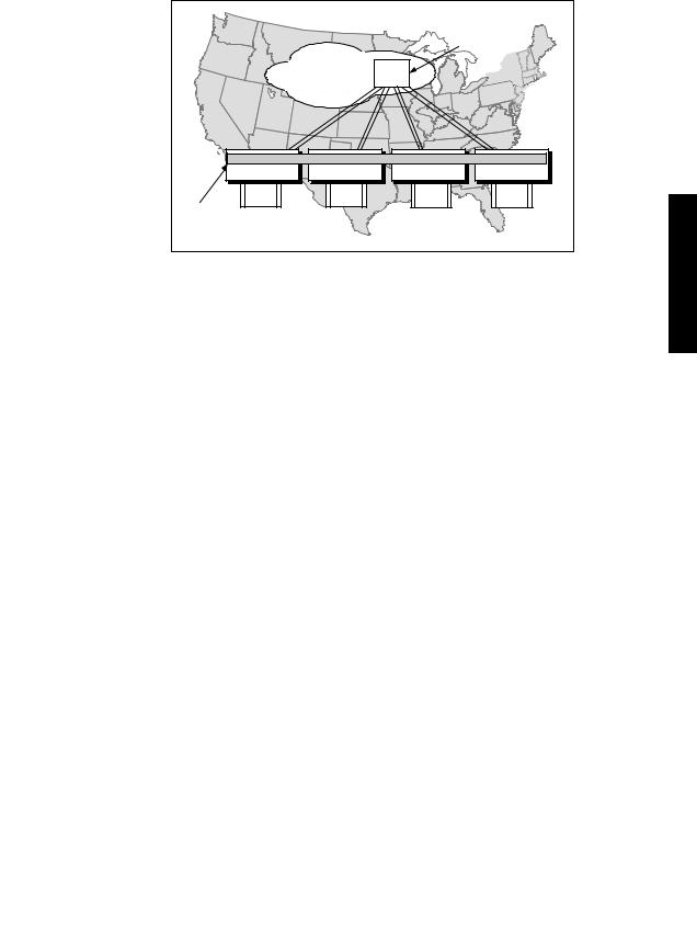
Service arrays are closely tied to network trunk groups. Typically, service arrays are defined in instances where you have similar peripheral services defined on multiple VRUs and the VRUs all share the same network trunk group. By grouping the services of multiple VRUs into a service array, you can send calls to a single target (a service array) and let the network deliver the call to any one of the peripheral services that make up the service array.
The Call Center Enterprise |
29 |
Figure 9 shows an example of how service arrays relate to peripheral services and network trunk groups.
|
|
|
|
Network Trunk |
|
|
|
|
Group |
|
Routing Client |
|
DAL |
|
|
(IXC, PG) |
Trunks |
|
|
|
|
|
T1’s |
|
Dal_VRU1.Sales Dal_VRU2.Sales |
Dal_VRU3.Sales Dal_VRU4.Sales |
|||
Dal_VRU1.Help Dal_VRU2.Help |
|
Dal_VRU3.Help Dal_VRU4.Help |
||
VRU1 |
VRU2 |
|
VRU3 |
VRU4 |
Service |
|
|
|
|
Array |
|
|
|
|
Figure 9: Service Arrays
When several VRUs each support a peripheral service, as shown in Figure 9, you can define a service array for those VRUs. You can define one or more peripheral services on a VRU. Each VRU can have more than one service array defined.
Service arrays also give you flexibility in reporting on call center performance by providing a separate view into the performance of peripheral services on VRUs. For example, in Figure 9 a peripheral service report would provide data for one VRU. An enterprise service report would provide data for an arbitrary collection of VRUs and ACDs. A service array report, however, would provide data on one group of VRUs that are sharing a network trunk group.
1.2.5.Routes
A route is a value that is returned by a routing script. The value maps to a target at a peripheral. This target can be a service, skill group, agent, or translation route. More simply, a route is the destination of the call after the ICR has made its routing decisions.
Overview .1

30 Overview
Routes are associated with a single peripheral and are not organized on an enterprise-wide basis. Figure 10 shows some examples of routes and how they map to individual peripheral targets.
|
Routes |
|
|
|
|
|
|
Boston Sales |
|
|
|
|
Boston.Sales.Sec |
|
|
|
|
Agent 123 |
ACD |
Denver Sales |
|
|
Boston.Trunks + DNIS |
|
|
|
|
||
Denver.Sales.Pri |
|
|
|
|
Agent 325 |
ACD |
|
|
|
Denver.Trunks + DNIS |
|
|
|
|
|
|
|
|
|
|
|
Dallas.Sales |
|
|
|
|
Dallas.Sales.Pri |
|
|
|
ACD |
Agent |
81 |
|
|
|
Dallas.Trunks + DNIS |
|
|
Figure 10: Routes
The ICR converts the route value that is returned by the routing script to a routing label. This routing label is then returned to the routing client. The routing client uses the routing label to deliver the call to the appropriate trunk group and DNIS combination.
See also: The Intelligent CallRouter System Manager Guide contains a more in-depth discussion of routes and how they are mapped to specific targets.
1.2.6.Other Parts of the Enterprise
In addition to viewing data for services, skill groups, agents, trunk groups, and routes, you can view data for the following call center entities:
Application Gateways
You can report on data related to the Application Gateways set up in the system. The GEOTELìGateway feature allows the ICR to interface to host systems that are running other call center applications.
The Application Gateway is implemented via a node in the ICR Script Editor. A routing script that contains an Application Gateway node can query an application running on a host system in order to obtain data to use in call routing. The ICR can then base subsequent routing decisions on the results obtained from the query.
Loading...