


 Loading...
Cisco Model DPC3825 and EPC3825
8x4 DOCSIS 3.0 Wireless
Residential Gateway User Guide
In This Document
IMPORTANT SAFETY INSTRUCTIONS ............................................................... |
2 |
Introduction............................................................................................................... |
12 |
What's In the Carton?............................................................................................... |
14 |
Front Panel Description ........................................................................................... |
15 |
Back Panel Description ............................................................................................ |
16 |
What Are the System Requirements for Internet Service?.................................. |
18 |
How Do I Subscribe to High-Speed Internet Service?......................................... |
19 |
Where Is the Best Location for My DOCSIS Residential Gateway? .................. |
20 |
How Do I Mount the Modem on a Wall? (Optional)........................................... |
21 |
How Do I Connect My Gateway for Internet Service?........................................ |
24 |
How Do I Configure My DOCSIS Residential Gateway?................................... |
26 |
Configure Wireless Settings .................................................................................... |
35 |
Configure Security.................................................................................................... |
51 |
Control Access to the Gateway............................................................................... |
60 |
Configure Applications and Gaming..................................................................... |
69 |
Manage the Gateway................................................................................................ |
75 |
Monitor Gateway Status .......................................................................................... |
84 |
Frequently Asked Questions................................................................................... |
91 |
Tips for Improved Performance ............................................................................. |
95 |
Front Panel LED Status Indicator Functions......................................................... |
96 |
Notices...................................................................................................................... |
100 |
IMPORTANT SAFETY INSTRUCTIONS
IMPORTANT SAFETY INSTRUCTIONS
Notice to Installers
The servicing instructions in this notice are for use by qualified service personnel only. To reduce the risk of electric shock, do not perform any servicing other than that contained in the operating instructions, unless you are qualified to do so.
Notice à l’attention des installateurs de réseaux câblés
Les instructions relatives aux interventions d’entretien, fournies dans la présente notice, s’adressent exclusivement au personnel technique qualifié. Pour réduire les risques de chocs électriques, n’effectuer aucune intervention autre que celles décrites dans le mode d'emploi et les instructions relatives au fonctionnement, à moins que vous ne soyez qualifié pour ce faire.
2 |
4021196 Rev B |
IMPORTANT SAFETY INSTRUCTIONS
Mitteilung für CATV-Techniker
Die in dieser Mitteilung aufgeführten Wartungsanweisungen sind ausschließlich für qualifiziertes Fachpersonal bestimmt. Um die Gefahr eines elektrischen Schlags zu reduzieren, sollten Sie keine Wartungsarbeiten durchführen, die nicht ausdrücklich in der Bedienungsanleitung aufgeführt sind, außer Sie sind zur Durchführung solcher Arbeiten qualifiziert.
Aviso a los instaladores de sistemas CATV
Las instrucciones de reparación contenidas en el presente aviso son para uso exclusivo por parte de personal de mantenimiento cualificado. Con el fin de reducir el riesgo de descarga eléctrica, no realice ninguna otra operación de reparación distinta a las contenidas en las instrucciones de funcionamiento, a menos que posea la cualificación necesaria para hacerlo.
20080814_Installer820_Intl
4021196 Rev B |
3 |

IMPORTANT SAFETY INSTRUCTIONS
IMPORTANT SAFETY INSTRUCTIONS
1)Read these instructions.
2)Keep these instructions.
3)Heed all warnings.
4)Follow all instructions.
5)Do not use this apparatus near water.
6)Clean only with dry cloth.
7)Do not block any ventilation openings. Install in accordance with the manufacturer's instructions.
8)Do not install near any heat sources such as radiators, heat registers, stoves, or other apparatus (including amplifiers) that produce heat.
9)Do not defeat the safety purpose of the polarized or grounding-type plug. A polarized plug has two blades with one wider than the other. A grounding-type plug has two blades and a third grounding prong. The wide blade or the third prong are provided for your safety. If the provided plug does not fit into your outlet, consult an electrician for replacement of the obsolete outlet.
10)Protect the power cord from being walked on or pinched particularly at plugs, convenience receptacles, and the point where they exit from the apparatus.
11)Only use attachments/accessories specified by the manufacturer.
12)Use only with the cart, stand, tripod, bracket, or table specified by the manufacturer, or sold with the apparatus. When a cart is used, use caution when moving the cart/apparatus combination to avoid injury from tip-over.
13)Unplug this apparatus during lightning storms or when unused for long periods of time.
14)Refer all servicing to qualified service personnel. Servicing is required when the apparatus has been damaged in any way, such as a power-supply cord or plug is damaged, liquid has been spilled or objects have fallen into the apparatus, the apparatus has been exposed to rain or moisture, does not operate normally, or has been dropped.
Power Source Warning
A label on this product indicates the correct power source for this product. Operate this product only from an electrical outlet with the voltage and frequency indicated on the product label. If you are uncertain of the type of power supply to your home or business, consult your service provider or your local power company.
The AC inlet on the unit must remain accessible and operable at all times.
Ground the Product
WARNING: Avoid electric shock and fire hazard! If this product connects to coaxial cable wiring, be sure the cable system is grounded (earthed). Grounding provides some protection against voltage surges and built-up static charges.
4 |
4021196 Rev B |
IMPORTANT SAFETY INSTRUCTIONS
Protect the Product from Lightning
In addition to disconnecting the AC power from the wall outlet, disconnect the signal inputs.
Verify the Power Source from the On/Off Power Light
When the on/off power light is not illuminated, the apparatus may still be connected to the power source. The light may go out when the apparatus is turned off, regardless of whether it is still plugged into an AC power source.
Eliminate AC Mains Overloads
WARNING: Avoid electric shock and fire hazard! Do not overload AC mains, outlets, extension cords, or integral convenience receptacles. For products that require battery power or other power sources to operate them, refer to the operating instructions for those products.
Provide Ventilation and Select a Location
Remove all packaging material before applying power to the product.
Do not place this apparatus on a bed, sofa, rug, or similar surface.
Do not place this apparatus on an unstable surface.
Do not install this apparatus in an enclosure, such as a bookcase or rack, unless the installation provides proper ventilation.
Do not place entertainment devices (such as VCRs or DVDs), lamps, books, vases with liquids, or other objects on top of this product.
Do not block ventilation openings.
Protect from Exposure to Moisture and Foreign Objects
WARNING: Avoid electric shock and fire hazard! Do not expose this product to dripping or splashing liquids, rain, or moisture. Objects filled with liquids, such as vases, should not be placed on this apparatus.
WARNING: Avoid electric shock and fire hazard! Unplug this product before cleaning. Do not use a liquid cleaner or an aerosol cleaner. Do not use a magnetic/static cleaning device (dust remover) to clean this product.
WARNING: Avoid electric shock and fire hazard! Never push objects through the openings in this product. Foreign objects can cause electrical shorts that can result in electric shock or fire.
Service Warnings
WARNING: Avoid electric shock! Do not open the cover of this product. Opening or removing the cover may expose you to dangerous voltages. If you open the cover, your warranty will be void. This product contains no user-serviceable parts.
4021196 Rev B |
5 |
IMPORTANT SAFETY INSTRUCTIONS
Check Product Safety
Upon completion of any service or repairs to this product, the service technician must perform safety checks to determine that this product is in proper operating condition.
Protect the Product When Moving It
Always disconnect the power source when moving the apparatus or connecting or disconnecting cables.
20090915_Modem No Battery_Safety
6 |
4021196 Rev B |
IMPORTANT SAFETY INSTRUCTIONS
United States FCC Compliance
This device has been tested and found to comply with the limits for a Class B digital device, pursuant to part 15 of the FCC Rules. These limits are designed to provide reasonable protection against such interference in a residential installation. This equipment generates, uses, and can radiate radio frequency energy. If not installed and used in accordance with the instructions, it may cause harmful interference to radio communications. However, there is no guarantee that interference will not occur in a particular installation. If this equipment does cause harmful interference to radio or television reception, which can be determined by turning the equipment OFF and ON, the user is encouraged to try to correct the interference by one or more of the following measures:
Reorient or relocate the receiving antenna.
Increase the separation between the equipment and receiver.
Connect the equipment into an outlet on a circuit different from that to which the receiver is connected.
Consult the service provider or an experienced radio/television technician for help.
Any changes or modifications not expressly approved by Cisco Systems, Inc., could void the user's authority to operate the equipment.
The information shown in the FCC Declaration of Conformity paragraph below is a requirement of the FCC and is intended to supply you with information regarding the FCC approval of this device. The phone numbers listed are for FCC-related questions only and not intended for questions regarding the connection or operation for this device. Please contact your service provider for any questions you may have regarding the operation or installation of this device.
 Declaration of Conformity
This device complies with Part 15 of FCC |
DOCSIS Residential Gateway |
Rules. Operation is subject to the following two |
Model: DPC3825/EPC3825 |
conditions: 1) the device may not cause |
Manufactured by: |
harmful interference, and 2) the device must |
Cisco Systems, Inc. |
accept any interference received, including |
5030 Sugarloaf Parkway |
interference that may cause undesired |
Lawrenceville, Georgia 30044 USA |
operation. |
Telephone: 770-236-1077 |
|
|
Canada EMI Regulation
This Class B digital apparatus complies with Canadian ICES-003.
Cet appareil numérique de la class B est conforme à la norme NMB-003 du Canada.
4021196 Rev B |
7 |
IMPORTANT SAFETY INSTRUCTIONS
Dynamic Frequency Selection (DFS) Dual Band Frequencies
Some configurations of this product may operate in the 5150-5250MHz and 5470-5725MHz bands. If you select a channel in these frequency ranges, the product is
restricted to indoor operation only per FCC guidance. The use of this product on the affected frequencies when outside is in non-compliance of the FCC regulations and guidelines.
Radiation Exposure Statements
Note: This transmitter must not be co-located or operated in conjunction with any other antenna or transmitter. This equipment should be installed and operated with a minimum distance of 7.9 inches (20 cm) between the radiator and your body.
US
This system has been evaluated for RF exposure for humans in reference to ANSI C 95.1 (American National Standards Institute) limits. The evaluation was based in accordance with FCC OET Bulletin 65C rev 01.01 in compliance with Part 2.1091 and Part 15.27. The minimum separation distance from the antenna to general bystander is 7.9 inches (20 cm) to maintain compliance.
Canada
This system has been evaluated for RF exposure for humans in reference to ANSI C 95.1 limits. The evaluation was based on evaluation per RSS-102 Rev 2. The minimum separation distance from the antenna to general bystander is 7.9 inches (20 cm) to maintain compliance.
EU
This system has been evaluated for RF exposure for humans in reference to the ICNIRP (International Commission on Non-Ionizing Radiation Protection) limits. The evaluation was based on the EN 50385 Product Standard to Demonstrate Compliance of Radio Base Stations and Fixed Terminals for Wireless Telecommunications Systems with basic restrictions or reference levels related to Human Exposure to Radio Frequency Electromagnetic Fields from 300 MHz to 40 GHz. The minimum separation distance from the antenna to general bystander is 20 cm (7.9 inches).
Australia
This system has been evaluated for RF exposure for humans as referenced in the Australian Radiation Protection standard and has been evaluated to the ICNIRP (International Commission on Non-Ionizing Radiation Protection) limits. The minimum separation distance from the antenna to general bystander is 20 cm (7.9 inches).
20091016 FCC DSL_Dom and Intl
8 |
4021196 Rev B |

IMPORTANT SAFETY INSTRUCTIONS
CE Compliance
Declaration of Conformity with Regard to the EU Directive 1999/5/EC (R&TTE Directive)
This declaration is only valid for configurations (combinations of software, firmware and hardware) supported or provided by Cisco Systems for use within the EU. The use of software or firmware not supported or provided by Cisco Systems may result in the equipment no longer being compliant with the regulatory requirements.
4021196 Rev B |
9 |

IMPORTANT SAFETY INSTRUCTIONS
Note: The full declaration of conformity for this product can be found in the Declarations of Conformity and Regulatory Information section of the appropriate product hardware installation guide, which is available on Cisco.com.
The following standards were applied during the assessment of the product against the requirements of the Directive 1999/5/EC:
Radio: EN 300 328
EMC: EN 301 489-1 and EN 301 489-17 Safety: EN 60950 and EN 50385
The CE mark and class-2 identifier are affixed to the product and its packaging. This product conforms to the following European directives:
-1999/5/EC
National Restrictions
This product is for indoor use only.
France
For 2.4 GHz, the output power is restricted to 10 mW EIRP when the product is used outdoors in the band 2454 - 2483,5 MHz. There are no restrictions when used in other parts of the 2,4 GHz band. Check http://www.arcep.fr/ for more details.
Pour la bande 2,4 GHz, la puissance est limitée à 10 mW en p.i.r.e. pour les équipements utilisés en extérieur dans la bande 2454 - 2483,5 MHz. Il n'y a pas de restrictions pour des utilisations dans d'autres parties de la bande 2,4 GHz. Consultez http://www.arcep.fr/ pour de plus amples détails.
Italy
This product meets the National Radio Interface and the requirements specified in the National Frequency Allocation Table for Italy. Unless this wireless LAN product is operating within the boundaries of the owner's property, its use requires a “general authorization.” Please check http://www.comunicazioni.it/it/ for more details.
Questo prodotto è conforme alla specifiche di Interfaccia Radio Nazionali e rispetta il Piano Nazionale di ripartizione delle frequenze in Italia. Se non viene installato all 'interno del proprio fondo, l'utilizzo di prodotti Wireless LAN richiede una “Autorizzazione Generale”. Consultare http://www.comunicazioni.it/it/ per maggiori dettagli.
10 |
4021196 Rev B |
IMPORTANT SAFETY INSTRUCTIONS
Latvia
The outdoor usage of the 2.4 GHz band requires an authorization from the Electronic Communications Office. Please check http://www.esd.lv for more details.
2,4 GHz frekvenču joslas izmantošanai ārpus telpām nepieciešama atļauja no Elektronisko sakaru direkcijas. Vairāk informācijas: http://www.esd.lv.
Note: The regulatory limits for maximum output power are specified in EIRP. The EIRP level of a device can be calculated by adding the gain of the antenna used (specified in dBi) to the output power available at the connector (specified in dBm).
Antennas
Use only the antenna supplied with the product.
20090312 CE_Gateway
4021196 Rev B |
11 |
Introduction
Introduction
Welcome to the exciting world of high-speed Internet service. Your new Cisco® Model DPC3825 DOCSIS® 3.0 or EPC3825 EuroDOCSIS™ Wireless Residential Gateway is a cable modem that meets industry standards for high-speed data connectivity. The DPC3825 and EPC3825 residential gateway delivers data and wired (Ethernet) or wireless gateway capabilities to connect a variety of devices in the home or small office and support high-speed data access, all in one device. With a DPC3825 or EPC3825 residential gateway, your Internet enjoyment, home and business communications, and personal productivity will surely soar.
This guide provides procedures and recommendations for placing, installing, configuring, operating, and troubleshooting your DPC3825 and EPC3825 residential gateway for high-speed Internet for your home or office. Refer to the appropriate section in this guide for the specific information you need for your situation. Contact your service provider for more information about subscribing to these services.
Benefits and Features
Your new DPC3825 and EPC3825 residential gateway offers the following outstanding benefits and features:
Compliant with DOCSIS 3.0, 2.0, and 1.x standards along with PacketCable™ and EuroPacketCable™ specifications to deliver high-end performance and reliability
High performance broadband Internet connectivity to energize your online experience
Four 1000/100/10BASE-T Ethernet ports to provide wired connectivity
802.11n Wireless Access Point
Wireless Protected Setup (WPS), including a push button switch to activate WPS for simplified and secure wireless setup
User configurable Parental Control blocks access to undesirable Internet sites
Advanced firewall technology deters hackers and protects the home network from unauthorized access
Attractive compact design that allows for vertical, horizontal, or wall-mounted operation
12 |
4021196 Rev B |
Introduction
Color-coded interface ports and corresponding cables simplify installation and setup
DOCSIS-5 compliant LED labeling and behavior provides a user and technician friendly method to check operational status and act as a troubleshooting tool
Allows automatic software upgrades by your service provider
4021196 Rev B |
13 |
What's In the Carton?
What's In the Carton?
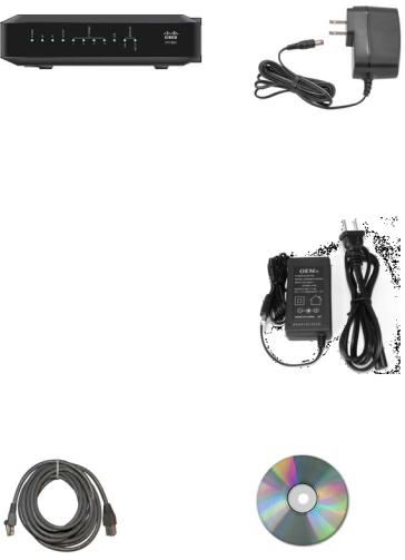
When you receive your wireless residential gateway, you should check the equipment and accessories to verify that each item is in the carton and that each item is undamaged. The carton contains the following items:
One of the DOCSIS Residential Gateway models (DPC3825 or EPC3825)
One Ethernet cable (CAT5/RJ-45)
One wall-mount style power adapter (models requiring external power supply)
OR
One desktop-style power adapter (models requiring external power supply)
One CD-ROM
If any of these items are missing or damaged, please contact your service provider for assistance.
Note: You will need an optional cable signal splitter and additional standard RF coaxial cables if you want to connect a VCR, a Digital Home Communications Terminal (DHCT) or a set-top converter, or a TV to the same cable connection as your wireless residential gateway.
14 |
4021196 Rev B |
Front Panel Description
Front Panel Description
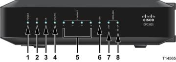
The front panel of your residential gateway provides LED status indicators that indicate how well and at what state your residential gateway is operating. See Front Panel LED Status Indicator Functions (on page 96), for more information on front panel LED status indicator functions.
Model DPC3825 shown here
1POWER—ON, power is applied to the wireless residential gateway
2DS—ON, the wireless residential gateway is receiving data from the cable network
3US—On, the wireless residential gateway is sending data to the cable network
4ONLINE—ON, the wireless residential gateway is registered on the network and fully operational
5ETHERNET 1 - 4—ON, a device is connected to one of the Ethernet ports. BLINKING indicates that data is being transferred over the Ethernet connection
6USB—ON, a device is connected to the USB port. BLINKING indicates that data is being transferred over the USB connection
7WIRELESS LINK—ON, the Wireless Access Point is operational. BLINKING indicates that data is being transferred over the wireless connection. OFF indicates that the wireless access point has been disabled by the user
8WIRELESS SETUP—OFF (normal condition) wireless setup is not active. BLINKING indicates the user has activated wireless setup to add new wireless clients on the wireless network
4021196 Rev B |
15 |
Back Panel Description
Back Panel Description
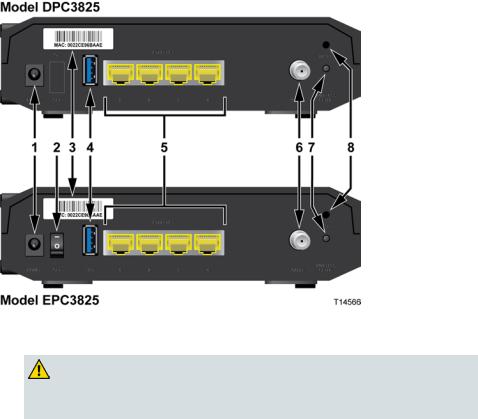
The following illustrations show the description and function of the back panel components on the Cisco DPC3825 residential gateway.
1POWER—Connects the residential gateway to the AC power adapter that is provided with your residential gateway
CAUTION:
Avoid damage to your equipment. Only use the power supply that is provided with your residential gateway.
2ON/OFF SWITCH (European models only)—Allows you to power of the residential gateway without removing the power cord
3MAC ADDRESS LABEL—Displays the MAC address of the residential gateway
4USB—Connects to selected client devices
5ETHERNET—Four RJ-45 Ethernet ports connect to the Ethernet port on your PC or your home network
6CABLE—F-connector connects to an active cable signal from your service provider
7WIRELESS SETUP—Pressing this switch initiates wireless setup, this feature allows the user to add new Wireless Protected Setup (WPS) compliant wireless clients to the home network
16 |
4021196 Rev B |

Back Panel Description
8RESET—A momentary pressing (1-2 seconds) of this switch reboots the EMTA. Pressing the switch for more than ten seconds first causes a reset-to-factory- default of all settings and then reboots the gateway
CAUTION:
The Reset button is for maintenance purposes only. Do not use unless instructed to do so by your cable service provider. Doing so may cause you to lose any cable modem settings you have selected.
4021196 Rev B |
17 |
What Are the System Requirements for Internet Service?
What Are the System Requirements for Internet Service?
To ensure that your residential gateway operates efficiently for high-speed Internet service, verify that all of the Internet devices on your system meet or exceed the following minimum hardware and software requirements.
Note: You will also need an active cable input line and an Internet connection.
Minimum System Requirements for a PC
A PC with a Pentium MMX 133 processor or greater
32 MB of RAM
Web browsing software
CD-ROM drive
Minimum System Requirements for Macintosh
MAC OS 7.5 or later
32 MB of RAM
System Requirements for an Ethernet Connection
A PC with Microsoft Windows 2000 operating system (or later) with TCP/IP protocol installed, or an Apple Macintosh computer with TCP/IP protocol installed
An active 10/100/1000BASE-T Ethernet network interface card (NIC) installed
18 |
4021196 Rev B |
How Do I Subscribe to High-Speed Internet Service?
How Do I Subscribe to High-Speed Internet Service?
Before you can use your residential gateway, you need to have a high-speed Internet access account. If you do not have a high-speed Internet access account, you need to set up an account with your local service provider. Choose one of the options in this section.
I Do Not Have a High-Speed Internet Access Account
If you do not have a high-speed Internet access account, your service provider will set up your account and become your Internet Service Provider (ISP). Internet access enables you to send and receive e-mail, access the World Wide Web, and receive other Internet services.
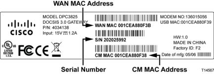
You will need to give your service provider the following information:
The serial number of the modem
The Media Access Control (MAC) address of the modem (CM MAC)
Other MAC address numbers as needed
These numbers appear on a bar code label located on the residential gateway. The serial number consists of a series of alphanumeric characters preceded by S/N. The MAC address consists of a series of alphanumeric characters preceded by CM MAC. The following illustration shows a sample bar code label.
Write down these numbers in the space provided here.
Serial Number _______________________
MAC Address ________________________
I Already Have an Existing High-Speed Internet Access Account
If you have an existing high-speed Internet access account, you must give your service provider the serial number and the MAC address of the residential gateway. Refer to the serial number and MAC address information listed previously in this section.
4021196 Rev B |
19 |
Where Is the Best Location for My DOCSIS Residential Gateway?
Where Is the Best Location for My DOCSIS Residential Gateway?
The ideal location for your residential gateway is where it has access to outlets and other devices. Think about the layout of your home or office, and consult with your service provider to select the best location for your residential gateway. Read this user guide thoroughly before you decide where to place your residential gateway.
Consider these recommendations:
Choose a location close to your computer if you will also use the residential gateway for high-speed Internet service.
Choose a location that is near an existing RF coaxial connection to eliminate the need for an additional RF coaxial outlet.
Choose a location that is relatively protected from accidental disturbance or harm, such as a closet, basement, or other protected area.
Choose a location so that there is plenty of room to guide the cables away from the modem without straining or crimping them.
Airflow around the residential gateway should not be restricted.
Read this user guide thoroughly before installing the residential gateway.
20 |
4021196 Rev B |
How Do I Mount the Modem on a Wall? (Optional)
How Do I Mount the Modem on a Wall? (Optional)
You can mount the residential gateway on a wall using two wall anchors, two screws, and the mounting slots located on the unit. The modem can be mounted vertically or horizontally.
Before You Begin
Before you begin, choose an appropriate mounting place. The wall can be made of cement, wood, or drywall. The mounting location should be free of obstructions on all sides, and the cables should be able to easily reach the residential gateway without strain. Leave sufficient clearance between the bottom of the residential gateway and any flooring or shelving underneath to allow access to cabling. In addition, leave enough slack in all cables so that the residential gateway can be removed for any required maintenance without disconnecting the cables. Also, verify that you have the following items:
Two wall anchors for #8 x 1-inch screws
Two #8 x 1-inch pan head sheet metal screws
Drill with a 3/16-in. wood or masonry bit, as appropriate for the wall composition
A copy of the wall-mounting illustrations shown on the following pages Mount the modem as shown in one of the following illustrations.
4021196 Rev B |
21 |
How Do I Mount the Modem on a Wall? (Optional)
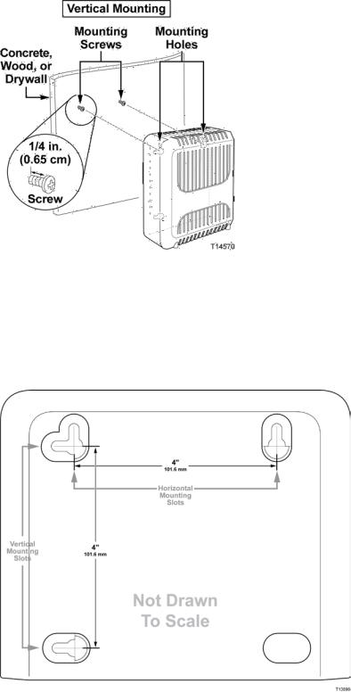
Location and Dimensions of the Wall-Mounting Slots
The following illustration shows the location and dimensions of the wall-mounting slots on the bottom of the modem. Use the information on this page as a guide for mounting your modem to the wall.
22 |
4021196 Rev B |
How Do I Mount the Modem on a Wall? (Optional)
Mounting the Residential Gateway on a Wall
1Using a drill with a 3/16-inch bit, drill two holes at the same height and 4 inches apart.
Note: The preceding graphic illustrates the location of the mounting holes on the back of the residential gateway.
2Are you mounting the residential gateway into a drywall or concrete surface where a wooden stud is available?
If yes, go to step 3.
If no, drive the anchor bolts into the wall, and install the mounting screws into the anchor bolts; leave a gap of about 1/4-inch between the screw head and the wall. Then, go to step 4.
3Install the mounting screws into the wall; leave a gap of about 1/4-inch between the screw head and the wall. Then, go to step 4.
4Verify that no cables or wires are connected to the residential gateway.
5Lift the residential gateway into position. Slip the large end of both mounting slots (located in the back of the residential gateway) over the mounting screws, and then slide the residential gateway down until the narrow end of the keyhole slot contacts the screw shaft.
Important: Verify that the mounting screws securely support the residential gateway before you release the unit.
4021196 Rev B |
23 |
How Do I Connect My Gateway for Internet Service?
How Do I Connect My Gateway for Internet Service?
You can use your residential gateway to provide Internet access, and you can share that Internet connection with other Internet devices in your home or office. Sharing one connection among many devices is called networking.
Connecting and Installing Internet Devices
Professional installation may be available. Contact your local service provider for further assistance.
To connect devices
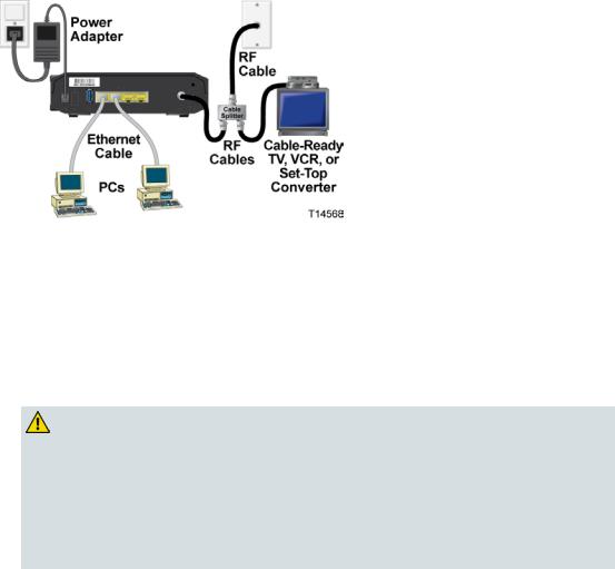
The following diagram illustrates one of the various networking options that are available to you.
Connecting the Residential Gateway for High-Speed Data Service
The following installation procedure ensures proper setup and configuration for the residential gateway.
1Choose an appropriate and safe location to install the residential gateway (close to a power source, an active cable connection, your PC—if using high-speed Internet).
WARNING:
To avoid personal injury, follow the installation instructions in the exact order shown.
Wiring and connections must be properly insulated to prevent electrical shock.
Disconnect power from the residential gateway before attempting to connect to any device.
2Power off your PC and other networking device; then, unplug them from the power source.
24 |
4021196 Rev B |
How Do I Connect My Gateway for Internet Service?
3Connect the active RF coaxial cable from your service provider to the coax connector labeled CABLE on the back of the residential gateway.
Note: To connect a TV, DHCT, set-top, or VCR from the same cable connection, you will need to install a cable signal splitter (not included). Always check with your service provider before using a splitter as a splitter may degrade the signal.
4Connect your PC to the residential gateway using either of the following methods.
Ethernet Connection: Locate the yellow Ethernet cable, connect one end of the Ethernet cable to the Ethernet port on your PC, and connect the other end to the yellow ETHERNET port on the back of the residential gateway.
Note: To install more Ethernet devices than ports provided on the residential gateway, use an external multi-port Ethernet switch(s).
Wireless: Make sure that your wireless device is powered up. You will need to associate your wireless device with the wireless gateway once the gateway is operational. Follow the directions provided with your wireless device for associating with a wireless access point.
More information about the factory default configuration of your wireless gateway can be found later in this user guide in Configure Wireless Settings (on page 35).
5Locate the AC power cord provided with your residential gateway. Insert one end of the power cord into the AC connector on the back of the residential gateway. Then, plug the AC power cord into an AC outlet to power-up the residential gateway. The residential gateway will perform an automatic search to locate and sign on to the broadband data network. This process may take up to 2- 5 minutes. The modem will be ready for use when the POWER, DS, US and ONLINE LEDs on the front panel of the residential gateway stop blinking and remain on continuously.
6Plug in and power on your PC and other home network devices. The LINK LED on the residential gateway corresponding to the connected devices should be on or blinking.
7Once the residential gateway is online, most Internet devices will have immediate Internet access.
Note: If your PC does not have Internet access, refer to Frequently Asked Questions (on page 91) for information on how to configure your PC for TCP/IP. For Internet devices other than PCs, refer to the DHCP or IP Address configuration section of the User Guide or Operations Manual for those devices.
4021196 Rev B |
25 |
How Do I Configure My DOCSIS Residential Gateway?
How Do I Configure My DOCSIS Residential Gateway?
To configure your residential gateway, you must first access the WebWizard configuration pages. This section provides detailed instructions and procedures for accessing the WebWizard pages and for configuring your residential gateway to operate correctly. This section also presents examples and descriptions of each WebWizard configuration page. Use the WebWizard pages to customize your residential gateway to your needs rather than using the default settings. The WebWizard pages in this section are organized in the order shown on the Setup page.
Important: The WebWizard pages and the examples shown in this section are for illustration purposes only. Your pages may differ from the pages shown in this guide. The pages shown in this guide also represent the default values for the device.
Note: If you are not familiar with the network configuration procedures detailed in this section, contact your service provider before you attempt to change any of the residential gateway default settings.
Logging in to the Gateway for the First Time
The default configuration of the gateway uses IP address 192.168.0.1. If you have connected the gateway correctly and you have properly configured your computer, use the following steps to log in to the gateway as an administrator.
1 On your PC, open the web browser that you prefer to use.
26 |
4021196 Rev B |
How Do I Configure My DOCSIS Residential Gateway?
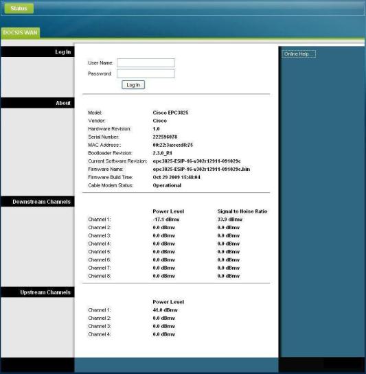
2In the address field, enter the following IP address: 192.168.0.1. A Status DOCSIS WAN login page similar to the following page opens.
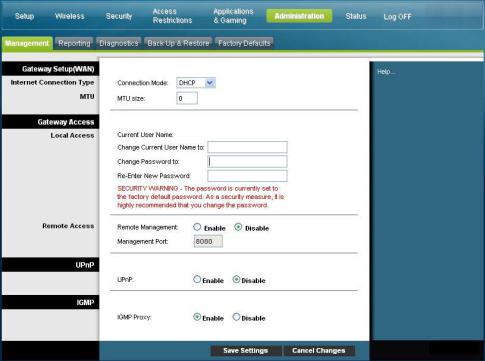
3On the Status DOCSIS WAN page, leave the User Name and Password field blank and click Log In. The gateway opens with an Administration Management page in the forefront. You can use the Administration Management page to set your User Name and Password.
Important: We highly recommend that you set up a new password to safeguard against the possibility of Internet attacks that look for devices operating with well-known or factory default user names and/or passwords.
4021196 Rev B |
27 |
How Do I Configure My DOCSIS Residential Gateway?
4On the Administration Management page, create a User Name and Password and then click Save Settings. Once you save the settings for your User Name and Password on the Administration Management page, the Setup Quick Setup page opens.
Important: You have the option to leave the password field blank (factory default). However, if you do not change your User Name and Password, you will be directed to the Administrative Management page each time you access the gateway. This serves as a reminder to set up your personalized password.
Once you have personalized your Password, subsequent logins will take you directly to the Setup Quick Setup page.
5After you make your selections, click Save Settings to apply your changes or
Cancel Changes to cancel.
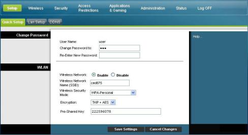
Setup > Quick Setup
The Setup Quick Setup page is the first page to open after you have logged on to your gateway. You can use the settings on this page to change your password and to configure the WLAN.
Important: The settings on this page are unique to your device. If you choose, you do not need to make any changes to the settings on this page. These default settings are all that you need to operate a secure wireless network.
28 |
4021196 Rev B |
How Do I Configure My DOCSIS Residential Gateway?
Configuring Quick Settings
Use the descriptions and instructions in the following table to configure the network settings for the device. After you make your selections, click Save Settings to apply your changes or click Cancel Changes to cancel.
Section |
Field Description |
Change Password |
User Name |
|
Displays the user name for the operator currently logged in |
|
Change Password to |
|
Allows you to change your password |
|
Re-Enter New Password |
|
Allows you to re-enter the new password. You must enter the same |
|
password as the one entered in the field Change Password to |
|
|
4021196 Rev B |
29 |

How Do I Configure My DOCSIS Residential Gateway?
Section |
Field Description |
WLAN |
Wireless Network |
|
Allows you to enable or disable the wireless network. Select the |
|
desired option: |
Enable
Disable
Wireless Network Name (SSID)
Allows you to enter a name for your wireless network or to use the default value. The value you enter he will be viewable on PCs and other wireless client devices such as the wireless network name.
Note: The factory default Service Set Identifier (SSID) is either the last 6 characters of the CM MAC Address or the SSID as identified on the product label.
Some service providers supply a special wireless configuration card that provides the SSID information and wireless security information.
Wireless Security Mode
Allows you to select a wireless security mode to help protect your network. If you select Disable then your wireless network is not secure and any wireless device within range may connect to it. See Wireless Security (on page 39) for detailed descriptions of wireless security modes.
Note: The factory default Wireless Security Mode is WPA or WPA2-Personal.
Encryption
Allows you to select a level of encryption based on the wireless security mode you choose. See Wireless Security (on page 39) for detailed descriptions of encryption.
Pre-Shared Key
The pre-shared key for the device. The key can be from 8 to 63 characters. The factory default Pre-Shared Key is equal to the 9-digit serial number of your gateway. The serial number can be found on the rating label attached to your wireless gateway.
Note: Your service provider may provide you with a wireless configuration card that contains SSID and wireless security configuration information for your home network that may differ from what is described above.
30 |
4021196 Rev B |
Loading...