


 Loading...
Catalyst 4500 E-Series Switches
Installation Guide
November 2007
Americas Headquarters
Cisco Systems, Inc. 170 West Tasman Drive
San Jose, CA 95134-1706 USA http://www.cisco.com Tel: 408 526-4000
800 553-NETS (6387) Fax: 408 527-0883
Text Part Number: OL-13972-01
THE SPECIFICATIONS AND INFORMATION REGARDING THE PRODUCTS IN THIS MANUAL ARE SUBJECT TO CHANGE WITHOUT NOTICE. ALL STATEMENTS, INFORMATION, AND RECOMMENDATIONS IN THIS MANUAL ARE BELIEVED TO BE ACCURATE BUT ARE PRESENTED WITHOUT WARRANTY OF ANY KIND, EXPRESS OR IMPLIED. USERS MUST TAKE FULL RESPONSIBILITY FOR THEIR APPLICATION OF ANY PRODUCTS.
THE SOFTWARE LICENSE AND LIMITED WARRANTY FOR THE ACCOMPANYING PRODUCT ARE SET FORTH IN THE INFORMATION PACKET THAT SHIPPED WITH THE PRODUCT AND ARE INCORPORATED HEREIN BY THIS REFERENCE. IF YOU ARE UNABLE TO LOCATE THE SOFTWARE LICENSE OR LIMITED WARRANTY, CONTACT YOUR CISCO REPRESENTATIVE FOR A COPY.
The following information is for FCC compliance of Class A devices: This equipment has been tested and found to comply with the limits for a Class A digital device, pursuant to part 15 of the FCC rules. These limits are designed to provide reasonable protection against harmful interference when the equipment is operated in a commercial environment. This equipment generates, uses, and can radiate radio-frequency energy and, if not installed and used in accordance with the instruction manual, may cause harmful interference to radio communications. Operation of this equipment in a residential area is likely to cause harmful interference, in which case users will be required to correct the interference at their own expense.
The following information is for FCC compliance of Class B devices: The equipment described in this manual generates and may radiate radio-frequency energy. If it is not installed in accordance with Cisco’s installation instructions, it may cause interference with radio and television reception. This equipment has been tested and found to comply with the limits for a Class B digital device in accordance with the specifications in part 15 of the FCC rules. These specifications are designed to provide reasonable protection against such interference in a residential installation. However, there is no guarantee that interference will not occur in a particular installation.
Modifying the equipment without Cisco’s written authorization may result in the equipment no longer complying with FCC requirements for Class A or Class B digital devices. In that event, your right to use the equipment may be limited by FCC regulations, and you may be required to correct any interference to radio or television communications at your own expense.
You can determine whether your equipment is causing interference by turning it off. If the interference stops, it was probably caused by the Cisco equipment or one of its peripheral devices. If the equipment causes interference to radio or television reception, try to correct the interference by using one or more of the following measures:
•Turn the television or radio antenna until the interference stops.
•Move the equipment to one side or the other of the television or radio.
•Move the equipment farther away from the television or radio.
•Plug the equipment into an outlet that is on a different circuit from the television or radio. (That is, make certain the equipment and the television or radio are on circuits controlled by different circuit breakers or fuses.)
Modifications to this product not authorized by Cisco Systems, Inc. could void the FCC approval and negate your authority to operate the product.
The Cisco implementation of TCP header compression is an adaptation of a program developed by the University of California, Berkeley (UCB) as part of UCB’s public domain version of the UNIX operating system. All rights reserved. Copyright © 1981, Regents of the University of California.
NOTWITHSTANDING ANY OTHER WARRANTY HEREIN, ALL DOCUMENT FILES AND SOFTWARE OF THESE SUPPLIERS ARE PROVIDED “AS IS” WITH ALL FAULTS. CISCO AND THE ABOVE-NAMED SUPPLIERS DISCLAIM ALL WARRANTIES, EXPRESSED OR IMPLIED, INCLUDING, WITHOUT LIMITATION, THOSE OF MERCHANTABILITY, FITNESS FOR A PARTICULAR PURPOSE AND NONINFRINGEMENT OR ARISING FROM A COURSE OF DEALING, USAGE, OR TRADE PRACTICE.
IN NO EVENT SHALL CISCO OR ITS SUPPLIERS BE LIABLE FOR ANY INDIRECT, SPECIAL, CONSEQUENTIAL, OR INCIDENTAL DAMAGES, INCLUDING, WITHOUT LIMITATION, LOST PROFITS OR LOSS OR DAMAGE TO DATA ARISING OUT OF THE USE OR INABILITY TO USE THIS MANUAL, EVEN IF CISCO OR ITS SUPPLIERS HAVE BEEN ADVISED OF THE POSSIBILITY OF SUCH DAMAGES.
CCVP, the Cisco logo, and Welcome to the Human Network are trademarks of Cisco Systems, Inc.; Changing the Way We Work, Live, Play, and Learn is a service mark of Cisco Systems, Inc.; and Access Registrar, Aironet, Catalyst, CCDA, CCDP, CCIE, CCIP, CCNA, CCNP, CCSP, Cisco, the Cisco Certified Internetwork Expert logo, Cisco IOS, Cisco Press, Cisco Systems, Cisco Systems Capital, the Cisco Systems logo, Cisco Unity, Enterprise/Solver, EtherChannel, EtherFast, EtherSwitch, Fast Step, Follow Me Browsing, FormShare, GigaDrive, HomeLink, Internet Quotient, IOS, iPhone, IP/TV, iQ Expertise, the iQ logo, iQ Net Readiness Scorecard, iQuick Study, LightStream, Linksys, MeetingPlace, MGX, Networkers, Networking Academy, Network Registrar, PIX, ProConnect, ScriptShare, SMARTnet, StackWise, The Fastest Way to Increase Your Internet Quotient, and TransPath are registered trademarks of Cisco Systems, Inc. and/or its affiliates in the United States and certain other countries.
All other trademarks mentioned in this document or Website are the property of their respective owners. The use of the word partner does not imply a partnership relationship between Cisco and any other company. (0711R)
Catalyst 4500 E-Series Switches Installation Guide
Copyright © 2007 Cisco Systems, Inc. All rights reserved.

|
|
|
|
|
|
|
|
C O N T E N T S |
||||
|
|
Preface vii |
|
|
|
|
|
|
|
|
|
|
|
|
Audience |
vii |
|
|
|
|
|
|
|
|
|
|
|
Organization |
vii |
|
|
|
|
|
|
|
|
|
|
|
Related Documentation |
viii |
|
|
|
|
|
|
|||
|
|
Conventions |
viii |
|
|
|
|
|
|
|
|
|
|
|
Obtaining Documentation and Submitting a Service Request |
xv |
|||||||||
|
Product Overview |
|
|
|
|
|
|
|
|
|||
C H A P T E R 1 |
1-1 |
|
|
|
|
|
|
|
||||
|
|
Switch Features |
1-1 |
|
|
|
|
|
|
|
||
|
|
Power Redundancy |
1-1 |
|
|
|
|
|
|
|||
|
|
Catalyst 4503-E Switch Features |
1-2 |
|
|
|
|
|||||
|
|
Catalyst 4506-E Switch Features |
1-5 |
|
|
|
|
|||||
|
|
Supervisor Engine Redundancy |
1-8 |
|
|
|
|
|||||
|
|
Catalyst 4507R-E Switch Features |
1-9 |
|
|
|
|
|||||
|
|
Catalyst 4510R-E Switch Features |
1-13 |
|
|
|
|
|||||
|
|
Supervisor Engines |
1-16 |
|
|
|
|
|
|
|
||
|
|
LEDs |
1-22 |
|
|
|
|
|
|
|
|
|
|
|
Gigabit Ethernet Uplink Ports |
1-22 |
|
|
|
|
|||||
|
|
10-Gigabit Ethernet Uplink Ports |
1-23 |
|
|
|
|
|||||
|
|
SFP Ports |
1-23 |
|
|
|
|
|
|
|
|
|
|
|
10/100BASE-T Management Port |
1-23 |
|
|
|
|
|||||
|
|
CONSOLE Port |
1-23 |
|
|
|
|
|
|
|
||
|
|
RESET Button |
1-24 |
|
|
|
|
|
|
|
||
|
|
Compact Flash Slot |
1-24 |
|
|
|
|
|
|
|||
|
|
Fan Assembly |
1-24 |
|
|
|
|
|
|
|
|
|
|
|
Power Supplies |
1-25 |
|
|
|
|
|
|
|
||
|
|
Power Supply LEDs |
1-28 |
|
|
|
|
|
|
|||
|
|
Power Supply Fan 1-28 |
|
|
|
|
|
|
||||
|
|
Load-Sharing Feature |
1-28 |
|
|
|
|
|
|
|||
|
|
Environmental Monitoring Feature |
1-29 |
|
|
|
|
|||||
|
|
1400 W DC Triple-input Power Supply Operational Modes |
1-29 |
|
|
|
||||||
|
|
System Architecture |
1-31 |
|
|
|
|
|
|
|||
|
|
Power Flow |
1-32 |
|
|
|
|
|
|
|
||
|
|
Power over Ethernet 1-32 |
|
|
|
|
|
|
||||
|
|
|
|
|
|
|
|
Catalyst 4500 E-Series Switches Installation Guide |
|
|
|
|
|
|
|
|
|
|
|
|
|
||||
|
OL-13972-01 |
|
|
|
|
|
|
|
|
|
iii |
|
|
|
|
|
|
|
|
|
|
|
|
||

Contents
|
|
|
|
|
Management Flow |
1-35 |
|
|
|
|
|
||||
|
|
|
|
|
Switching Traffic Flow |
|
1-36 |
|
|
|
|
|
|||
|
|
Preparing for Installation |
|
|
|
|
|
|
|
|
|
||||
C H A P T E R 2 |
|
2-1 |
|
|
|
|
|
|
|
|
|||||
|
|
|
|
|
Electrostatic Discharge |
2-2 |
|
|
|
|
|
|
|
|
|
|
|
|
|
|
Preventing Electrostatic Discharge Damage |
2-2 |
|
|
|||||||
|
|
|
|
|
Site Power Requirements and Heat Dissipation |
2-3 |
|
|
|||||||
|
|
|
|
|
Power Connection Guidelines for AC-Powered Systems |
2-3 |
|
||||||||
|
|
|
|
|
Power Connection Guidelines for DC-Powered Systems |
2-9 |
|
||||||||
|
|
|
|
|
Calculating DC Input Current |
2-9 |
|
|
|
|
|
||||
|
|
|
|
|
Ventilation 2-10 |
|
|
|
|
|
|
|
|
|
|
|
|
|
|
|
Calculating System Heat Dissipation |
|
2-11 |
|
|
|
|||||
|
|
|
|
|
Site-Planning Checklist |
2-11 |
|
|
|
|
|
|
|
||
|
|
Installing the Switch in a Rack |
|
|
|
|
|
|
|
||||||
C H A P T E R 3 |
|
|
3-1 |
|
|
|
|
|
|||||||
|
|
|
|
|
Checking the Shipping Container Contents |
3-1 |
|
|
|
||||||
|
|
|
|
|
Rack-Mounting the Switch |
3-2 |
|
|
|
|
|
|
|
||
|
|
|
|
|
Required Installation Tools |
|
3-2 |
|
|
|
|
|
|||
|
|
|
|
|
Rack-Mounting Catalyst 4500 E-series Switches |
3-3 |
|
||||||||
|
|
|
|
|
System Ground Connection Guidelines |
3-5 |
|
|
|
||||||
|
|
|
|
|
Parts and Required Tools |
|
3-6 |
|
|
|
|
|
|||
|
|
|
|
|
Connecting System Ground and Power |
3-6 |
|
|
|
||||||
|
|
Removing and Replacing FRUs |
|
|
|
|
|
|
|
||||||
C H A P T E R 4 |
|
|
4-1 |
|
|
|
|
|
|||||||
|
|
|
|
|
Removing and Replacing the Power Supply |
4-2 |
|
|
|
||||||
|
|
|
|
|
Required Tools |
4-4 |
|
|
|
|
|
|
|
|
|
|
|
|
|
|
Removing an AC-Input Power Supply |
|
4-4 |
|
|
|
|||||
|
|
|
|
|
Installing an AC-Input Power Supply |
|
4-6 |
|
|
|
|||||
|
|
|
|
|
Removing a DC-Input Power Supply |
|
4-8 |
|
|
|
|||||
|
|
|
|
|
Required Tools |
4-8 |
|
|
|
|
|
|
|
||
|
|
|
|
|
Removal Procedure |
4-8 |
|
|
|
|
|
||||
|
|
|
|
|
Installing a DC-Input Power Supply |
4-11 |
|
|
|
||||||
|
|
|
|
|
Required Tools |
4-11 |
|
|
|
|
|
|
|
||
|
|
|
|
|
Installation Procedure |
|
4-12 |
|
|
|
|
|
|||
|
|
|
|
|
Removing and Replacing the Chassis Fan Assembly 4-13 |
||||||||||
|
|
|
|
|
Required Tools |
4-13 |
|
|
|
|
|
|
|
|
|
|
|
|
|
|
Removing the Fan Assembly |
4-13 |
|
|
|
|
|
||||
|
|
|
|
|
Installing the Fan Assembly |
|
4-14 |
|
|
|
|
|
|||
|
|
|
|
Catalyst 4500 E-Series Switches Installation Guide |
|
|
|
|
|
|
|
|
|||
|
|
|
|
|
|
|
|
|
|
|
|
||||
|
|
|
|
|
|
|
|
|
|
|
|
|
|
|
|
|
iv |
|
|
|
|
|
|
|
|
|
|
|
|
OL-13972-01 |
|
|
|
|
|
|
|
|
|
|
|
|
|
|
|
||

Contents
|
|
Verifying the Installation |
|
4-15 |
|
|
|
|
|
|
|
||
|
|
Replacing Backplane Modules |
4-15 |
|
|
|
|
|
|
||||
|
|
Verify the New Modules |
4-18 |
|
|
|
|
|
|
|
|||
|
|
Supervisor Memory Upgrade |
4-19 |
|
|
|
|
|
|
|
|||
|
|
Tools and Equipment Needed |
4-19 |
|
|
|
|
|
|
||||
|
|
Removing Memory |
4-19 |
|
|
|
|
|
|
|
|
||
|
|
Installing SDRAM MiniDIMMs |
4-21 |
|
|
|
|
||||||
|
Troubleshooting 5-1 |
|
|
|
|
|
|
|
|
|
|
|
|
C H A P T E R 5 |
|
|
|
|
|
|
|
|
|
|
|
||
|
|
System Boot Verification |
5-2 |
|
|
|
|
|
|
|
|
||
|
|
Using LEDs to Identify Startup Problems |
5-2 |
|
|
|
|
||||||
|
|
System Messages |
5-4 |
|
|
|
|
|
|
|
|
|
|
|
|
Troubleshooting with Software |
5-4 |
|
|
|
|
|
|
||||
|
|
Troubleshooting the Power Supply |
5-4 |
|
|
|
|
|
|
||||
|
|
System Messages and Power Problems |
5-5 |
|
|
|
|||||||
|
|
Useful CLI Commands |
|
5-5 |
|
|
|
|
|
|
|
|
|
|
|
Power Supply Mixing |
5-6 |
|
|
|
|
|
|
|
|
||
|
|
Troubleshooting the Fan Assembly |
5-6 |
|
|
|
|
|
|
||||
|
|
System Messages and Fan Problems |
|
5-7 |
|
|
|
|
|||||
|
|
Useful CLI Commands |
|
5-7 |
|
|
|
|
|
|
|
|
|
|
|
Troubleshooting Backplane Modules |
5-7 |
|
|
|
|
|
|
||||
|
|
Troubleshooting Switching Modules |
5-8 |
|
|
|
|
|
|
||||
|
|
System Messages and Switching Modules |
5-9 |
|
|
|
|||||||
|
|
Useful CLI Commands |
|
5-9 |
|
|
|
|
|
|
|
|
|
|
|
Troubleshooting Supervisor Engines |
5-10 |
|
|
|
|
|
|
||||
|
|
System Messages and Supervisor Engines |
5-10 |
|
|
|
|||||||
|
|
Useful CLI Commands |
|
5-12 |
|
|
|
|
|
|
|
||
|
|
Standby Supervisor Engine Problems |
5-12 |
|
|
|
|||||||
|
|
Switch Self-reset |
5-13 |
|
|
|
|
|
|
|
|||
|
|
Ports 1/2 and 2/2 Do Not Function |
5-13 |
|
|
|
|||||||
|
|
Packet Loss |
5-13 |
|
|
|
|
|
|
|
|
|
|
|
|
Some Problems and Solutions |
5-14 |
|
|
|
|
|
|
||||
|
|
Module Not Online |
5-14 |
|
|
|
|
|
|
|
|||
|
|
Interface Problems |
5-15 |
|
|
|
|
|
|
|
|||
|
|
Workstation Is Unable to Log In to the Network 5-15 |
|||||||||||
|
|
NIC Compatibility Issues |
5-16 |
|
|
|
|
|
|
||||
|
|
Interface Is in Errdisable |
5-16 |
|
|
|
|
|
|
||||
|
|
Faulty Supervisor Engine |
5-16 |
|
|
|
|
|
|
||||
|
|
|
|
|
|
|
|
|
|
Catalyst 4500 E-Series Switches Installation Guide |
|
|
|
|
|
|
|
|
|
|
|
|
|
|
|||
|
OL-13972-01 |
|
|
|
|
|
|
|
|
|
|
v |
|
|
|
|
|
|
|
|
|
|
|
|
|
||

Contents
|
|
|
|
Boot Problems |
5-17 |
|
|
|
|
|
|
|
|
|
|
Contacting the Cisco Technical Assistance Center 5-18 |
|||||||
|
|
|
|
Serial Numbers |
5-19 |
|
|
|
|
|
|
|
|
Specifications A-1 |
|
|
|
|
|
|
|
||
A P P E N D I X |
A |
|
|
|
|
|
|
|
|||
|
|
|
|
Catalyst 4503-E Switch Specifications |
A-1 |
|
|
||||
|
|
|
|
Catalyst 4506-E Switch Specifications |
A-2 |
|
|
||||
|
|
|
|
Catalyst 4507R-E Switch Specifications |
A-3 |
||||||
|
|
|
|
Catalyst 4510R-E Switch Specifications |
A-5 |
||||||
|
|
|
|
Catalyst 4500 Power Supplies |
|
A-6 |
|
|
|
||
|
|
Repacking a Switch |
|
|
|
|
|
|
|
||
A P P E N D I X |
B |
B-1 |
|
|
|
|
|
|
|||
|
|
Initial Configuration for the Switch C-1 |
|
|
|||||||
A P P E N D I X |
C |
|
|
||||||||
|
|
|
|
Connecting to the Switch |
C-2 |
|
|
|
|
|
|
|
|
|
|
Starting the Terminal-Emulation Software |
C-2 |
||||||
|
|
|
|
Connecting to a Power Source |
|
C-2 |
|
|
|
||
|
|
|
|
Entering the Initial Configuration Information |
C-3 |
||||||
|
|
|
|
IP Settings C-3 |
|
|
|
|
|
|
|
|
|
|
|
Performing the Initial Configuration |
C-3 |
||||||
|
|
Module Overview and Specifications |
|
|
|
||||||
A P P E N D I X |
D |
D-1 |
|
|
|||||||
|
|
|
|
Catalyst 4500 Series Switches |
|
D-1 |
|
|
|
||
|
|
|
|
Catalyst 4500 E-Series Switches |
D-1 |
|
|
|
|||
|
|
|
|
Supervisor Engines |
D-1 |
|
|
|
|
|
|
|
|
|
|
Front-Panel Components |
D-3 |
|
|
|
|||
|
|
|
|
Ethernet Management Port |
D-4 |
|
|
|
|||
|
|
|
|
Console Port |
D-4 |
|
|
|
|
|
|
|
|
|
|
Supervisor Memory |
D-4 |
|
|
|
|
|
|
|
|
|
|
Switching Modules |
D-4 |
|
|
|
|
|
|
|
|
|
|
WS-X4606-X2-E D-5 |
|
|
|
|
|
||
|
|
|
|
WS-X4648-RJ45V-E D-5 |
|
|
|
|
|
||
|
|
|
|
WS-X4648-RJ45V+E D-6 |
|
|
|
|
|
||
|
|
|
|
Switching Module LEDs |
D-7 |
|
|
|
|||
|
|
|
|
Hot-Swapping Feature |
D-8 |
|
|
|
|
|
|
|
|
|
|
|
|
|
|
|
|
||
I N D E X |
|
|
|
|
|
|
|
|
|
||
|
|
|
Catalyst 4500 E-Series Switches Installation Guide |
|
|
|
|
|
|||
|
|
|
|
|
|
|
|
||||
|
|
|
|
|
|
|
|
|
|
|
|
|
vi |
|
|
|
|
|
|
|
|
OL-13972-01 |
|
|
|
|
|
|
|
|
|
|
|
||

Preface
Thispreface describesthe audience,organization,and conventionsofthe Catalyst4500 E-Series SwitchesInstallation Guide and providesinform ation on how to obtain related docum entation and technicalassistance.
Audience
Only trained and qualified servicepersonnel(asdefined in IEC 60950 and AS/NZS3260)should install, replace,orservice the equipm ent.
Organization
Thisguide isorganized asfollows:
Chapter |
Title |
Description |
|
|
|
Chapter1 |
ProductOverview |
Describesthe hardware features,com ponents,interfaces, |
|
|
and functionality ofthe Catalyst4500 E-seriesswitches. |
|
|
|
Chapter2 |
Preparing for |
Describeshow to prepareyoursitefortheinstallation ofthe |
|
Installation |
switch. |
|
|
|
Chapter3 |
Installing the Switch |
Describeshow to installthe Catalyst4500 E-series |
|
in a Rack |
switches. |
|
|
|
Chapter4 |
Rem oving and |
Describeshow torem oveandreplacefield-replaceableunits |
|
Replacing FRUs |
(FRUs). |
|
|
|
Chapter5 |
Troubleshooting |
Providestroubleshooting guidelinesfortheinitialhardware |
|
|
installation and suggestsstepsto help isolate and resolve |
|
|
problem s. |
|
|
|
Appendix A |
Specifications |
Liststhe cable and technicalspecificationsofthe |
|
|
Catalyst4500 E-seriesswitches. |
|
|
|
Appendix B |
Repacking aSwitch |
Providesinstructionsforrepacking yourCatalyst4500 |
|
|
E-seriesswitch in theeventthatyou haveto return itto the |
|
|
factory. |
|
|
|
Catalyst 4500 E-Series Switches Installation Guide
|
OL-13972-01 |
vii |
|

Preface
Related Documentation
Chapter |
Title |
Description |
|
|
|
Appendix C |
InitialConfiguration |
Providesa very m inim alconfiguration.Forfull |
|
forthe Switch |
configuration offeaturesand interfaces,referto the |
|
|
software configuration guide foryoursoftware release. |
|
|
|
Appendix D |
M oduleOverview and |
Providesspecificationsand otherinform ation aboutthe |
|
Specifications |
Catalyst4500 E-seriesswitching m odules. |
|
|
|
Related Documentation
Referto the following docum entsforadditionalCatalyst4500 seriesand Catalyst4500 E-series inform ation:
•Catalyst 4500 Series Module Installation Guide at http://www.cisco.com/en/US/docs/switches/lan/catalyst4500/hardware/module/guide/ mod_inst.html
for information about individual switching modules and supervisors not discussed in this publication.
•Regulatory Compliance and Safety Information for the Catalyst 4500 Series Switches at http://www.cisco.com/en/US/docs/switches/lan/catalyst4500/hardware/regulatory/compliance/ 78_13233.html
•The release note appropriate to your software version. Release notes are at: http://www.cisco.com/en/US/products/hw/switches/ps4324/prod_release_notes_list.html
•The software configuration guide appropriate to your software version. Software configuration guides are at: http://www.cisco.com/en/US/products/hw/switches/ps4324/products_installation_and_configurati on_guides_list.html
•The command reference appropriate to your software version. Command references are at: http://www.cisco.com/en/US/products/hw/switches/ps4324/prod_command_reference_list.html
•The system message guide appropriate to your software version. System message guides are at: http://www.cisco.com/en/US/products/hw/switches/ps4324/products_system_message_guides_list
.html
•There are a number of installation notes and technical tips available for this switch. The top level Catalyst 4500 and Catalyst 4500-E documentation and technical support page is at http://www.cisco.com/en/US/products/hw/switches/ps4324/tsd_products_support_ series_home.html
Conventions
Thisdocum entusesthe following conventions:
|
|
|
|
Convention |
Description |
|
|
|
|
|
|
|
|
|
|
|
|
|
|
boldfacefont |
Com m andsand keywordsare in boldface. |
||
|
|
|
|
|
|
|
|
|
|
|
|
italicfont |
Argum entsforwhich you supply valuesare in italics. |
||
|
|
|
|
||||
[ ] |
Elem entsin square bracketsare optional. |
||||||
|
|
|
|
|
|
|
|
|
|
|
Catalyst 4500 E-Series Switches Installation Guide |
||||
|
|
|
|||||
|
|
|
|
|
|
|
|
|
viii |
|
|
|
OL-13972-01 |
|
|
|
|
|
|
|
|||

Preface
Conventions
Convention |
Description |
|
|
{ x |y |z } |
Alternative keywordsare grouped in bracesand separated by verticalbars. |
|
|
[x |y |z ] |
Optionalalternative keywordsare grouped in bracketsand separated by |
|
verticalbars. |
|
|
string |
A nonquoted setofcharacters.Do notuse quotation m arksaround the |
|
string,because the string willinclude the quotation m arks. |
|
|
screen font |
Term inalsessionsand inform ation thatthe system displaysare in screen |
|
font. |
|
|
boldface screen |
Inform ation thatyou m ustenterisshown in boldface screen font. |
font |
|
|
|
italic screen font |
Argum entsforwhich you supply valuesare in italic screen font. |
|
|
Ctrl- |
Ctrl-representsthekeylabeledControl— forexam ple,thekeycom bination |
|
Ctrl-D m eansto hold down the Controlkey while you pressthe D key. |
|
|
< > |
Charactersthatdo notprint,such aspasswords,are shown within angle |
|
brackets. |
|
|
N otesuse the following conventions:
Note Means reader take note. Notes contain helpful suggestions or references to material not covered in the publication.
Cautionsuse the following conventions:
Caution M eansreaderbe careful.In thissituation,you m ightdo som ething thatcould resultin equipm entdam age orlossofdata.
Catalyst 4500 E-Series Switches Installation Guide
|
OL-13972-01 |
ix |
|

Preface
Conventions
Warnings use the following conventions:
Warning IMPORTANT SAFETY INSTRUCTIONS
This warning symbol means danger. You are in a situation that could cause bodily injury. Before you work on any equipment, be aware of the hazards involved with electrical circuitry and be familiar with standard practices for preventing accidents. Use the statement number provided at the end of each warning to locate its translation in the translated safety warnings that accompanied this device. Statement 1071
SAVE THESE INSTRUCTIONS
Waarschuwing BELANGRIJKE VEILIGHEIDSINSTRUCTIES
Dit waarschuwingssymbool betekent gevaar. U verkeert in een situatie die lichamelijk letsel kan veroorzaken. Voordat u aan enige apparatuur gaat werken, dient u zich bewust te zijn van de bij elektrische schakelingen betrokken risico's en dient u op de hoogte te zijn van de standaard praktijken om ongelukken te voorkomen. Gebruik het nummer van de verklaring onderaan de waarschuwing als u een vertaling van de waarschuwing die bij het apparaat wordt geleverd, wilt raadplegen.
BEWAAR DEZE INSTRUCTIES
Varoitus TÄRKEITÄ TURVALLISUUSOHJEITA
Tämä varoitusmerkki merkitsee vaaraa. Tilanne voi aiheuttaa ruumiillisia vammoja. Ennen kuin käsittelet laitteistoa, huomioi sähköpiirien käsittelemiseen liittyvät riskit ja tutustu onnettomuuksien yleisiin ehkäisytapoihin. Turvallisuusvaroitusten käännökset löytyvät laitteen mukana toimitettujen käännettyjen turvallisuusvaroitusten joukosta varoitusten lopussa näkyvien lausuntonumeroiden avulla.
SÄILYTÄ NÄMÄ OHJEET
Attention IMPORTANTES INFORMATIONS DE SÉCURITÉ
Ce symbole d'avertissement indique un danger. Vous vous trouvez dans une situation pouvant entraîner des blessures ou des dommages corporels. Avant de travailler sur un équipement, soyez conscient des dangers liés aux circuits électriques et familiarisez-vous avec les procédures couramment utilisées pour éviter les accidents. Pour prendre connaissance des traductions des avertissements figurant dans les consignes de sécurité traduites qui accompagnent cet appareil, référez-vous au numéro de l'instruction situé à la fin de chaque avertissement.
CONSERVEZ CES INFORMATIONS
Warnung WICHTIGE SICHERHEITSHINWEISE
Dieses Warnsymbol bedeutet Gefahr. Sie befinden sich in einer Situation, die zu Verletzungen führen kann. Machen Sie sich vor der Arbeit mit Geräten mit den Gefahren elektrischer Schaltungen und den üblichen Verfahren zur Vorbeugung vor Unfällen vertraut. Suchen Sie mit der am Ende jeder Warnung angegebenen Anweisungsnummer nach der jeweiligen Übersetzung in den übersetzten Sicherheitshinweisen, die zusammen mit diesem Gerät ausgeliefert wurden.
BEWAHREN SIE DIESE HINWEISE GUT AUF.
Catalyst 4500 E-Series Switches Installation Guide
|
x |
OL-13972-01 |
|
|
|
Preface
Conventions
Avvertenza IMPORTANTI ISTRUZIONI SULLA SICUREZZA
Questo simbolo di avvertenza indica un pericolo. La situazione potrebbe causare infortuni alle persone. Prima di intervenire su qualsiasi apparecchiatura, occorre essere al corrente dei pericoli relativi ai circuiti elettrici e conoscere le procedure standard per la prevenzione di incidenti. Utilizzare il numero di istruzione presente alla fine di ciascuna avvertenza per individuare le traduzioni delle avvertenze riportate in questo documento.
CONSERVARE QUESTE ISTRUZIONI
Advarsel VIKTIGE SIKKERHETSINSTRUKSJONER
Dette advarselssymbolet betyr fare. Du er i en situasjon som kan føre til skade på person. Før du begynner å arbeide med noe av utstyret, må du være oppmerksom på farene forbundet med elektriske kretser, og kjenne til standardprosedyrer for å forhindre ulykker. Bruk nummeret i slutten av hver advarsel for å finne oversettelsen i de oversatte sikkerhetsadvarslene som fulgte med denne enheten.
TA VARE PÅ DISSE INSTRUKSJONENE
Aviso INSTRUÇÕES IMPORTANTES DE SEGURANÇA
Este símbolo de aviso significa perigo. Você está em uma situação que poderá ser causadora de lesões corporais. Antes de iniciar a utilização de qualquer equipamento, tenha conhecimento dos perigos envolvidos no manuseio de circuitos elétricos e familiarize-se com as práticas habituais de prevenção de acidentes. Utilize o número da instrução fornecido ao final de cada aviso para localizar sua tradução nos avisos de segurança traduzidos que acompanham este dispositivo.
GUARDE ESTAS INSTRUÇÕES
¡Advertencia! INSTRUCCIONES IMPORTANTES DE SEGURIDAD
Este símbolo de aviso indica peligro. Existe riesgo para su integridad física. Antes de manipular cualquier equipo, considere los riesgos de la corriente eléctrica y familiarícese con los procedimientos estándar de prevención de accidentes. Al final de cada advertencia encontrará el número que le ayudará a encontrar el texto traducido en el apartado de traducciones que acompaña a este dispositivo.
GUARDE ESTAS INSTRUCCIONES
Varning! VIKTIGA SÄKERHETSANVISNINGAR
Denna varningssignal signalerar fara. Du befinner dig i en situation som kan leda till personskada. Innan du utför arbete på någon utrustning måste du vara medveten om farorna med elkretsar och känna till vanliga förfaranden för att förebygga olyckor. Använd det nummer som finns i slutet av varje varning för att hitta dess översättning i de översatta säkerhetsvarningar som medföljer denna anordning.
SPARA DESSA ANVISNINGAR
Catalyst 4500 E-Series Switches Installation Guide
|
OL-13972-01 |
xi |
|
Preface
Conventions
Catalyst 4500 E-Series Switches Installation Guide
|
xii |
OL-13972-01 |
|
|
|

Preface
Conventions
Aviso INSTRUÇÕES IMPORTANTES DE SEGURANÇA
Este símbolo de aviso significa perigo. Você se encontra em uma situação em que há risco de lesões corporais. Antes de trabalhar com qualquer equipamento, esteja ciente dos riscos que envolvem os circuitos elétricos e familiarize-se com as práticas padrão de prevenção de acidentes. Use o número da declaração fornecido ao final de cada aviso para localizar sua tradução nos avisos de segurança traduzidos que acompanham o dispositivo.
GUARDE ESTAS INSTRUÇÕES
Advarsel VIGTIGE SIKKERHEDSANVISNINGER
Dette advarselssymbol betyder fare. Du befinder dig i en situation med risiko for legemesbeskadigelse. Før du begynder arbejde på udstyr, skal du være opmærksom på de involverede risici, der er ved elektriske kredsløb, og du skal sætte dig ind i standardprocedurer til undgåelse af ulykker. Brug erklæringsnummeret efter hver advarsel for at finde oversættelsen i de oversatte advarsler, der fulgte med denne enhed.
GEM DISSE ANVISNINGER
Catalyst 4500 E-Series Switches Installation Guide
|
OL-13972-01 |
xiii |
|

Preface
Conventions
Catalyst 4500 E-Series Switches Installation Guide
|
xiv |
OL-13972-01 |
|
|
|

Preface
Obtaining Documentation and Submitting a Service Request
Obtaining Documentation and Submitting a Service Request
For information on obtaining documentation, submitting a service request, and gathering additional information, see the monthly What’s New in Cisco Product Documentation, which also lists all new and revised Cisco technical documentation, at:
http://www.cisco.com/en/US/docs/general/whatsnew/whatsnew.html
Subscribe to the What’s New in Cisco Product Documentation as a Really Simple Syndication (RSS) feed and set content to be delivered directly to your desktop using a reader application. The RSS feeds are a free service and Cisco currently supports RSS version 2.0.
Catalyst 4500 E-Series Switches Installation Guide
|
OL-13972-01 |
xv |
|

Preface
Obtaining Documentation and Submitting a Service Request
Catalyst 4500 E-Series Switches Installation Guide
|
xvi |
OL-13972-01 |
|
|
|

C H A P T E R 1
Product Overview
This chapter provides an overview of the features and components of the Catalyst 4500 E-series switches. The Catalyst 4500 E-series switches are the Catalyst 4503-E switch, the Catalyst 4506-E switch, the Catalyst 4507R-E switch, and the Catalyst 4510R-E switch. The information is presented in these major sections:
•Switch Features, page 1-1
•Supervisor Engines, page 1-16
•Fan Assembly, page 1-24
•Power Supplies, page 1-25
•System Architecture, page 1-31
Switch Features
The following sections describe the features of the Catalyst 4500 E-series switches:
•Power Redundancy, page 1-1
•Catalyst 4503-E Switch Features, page 1-2
•Catalyst 4506-E Switch Features, page 1-5
•Supervisor Engine Redundancy, page 1-8
•Catalyst 4507R-E Switch Features, page 1-9
•Catalyst 4510R-E Switch Features, page 1-13
Power Redundancy
All Catalyst 4500-E switches offer 1+1 power redundancy, so that in the event of a power interruption the switch can still operate using power from another circuit. The power supplies can also run in a combined mode so that chassis can have power from both supplies at once. You will need to use the power redundancy-mode command to configure combined mode. Redundant mode is the default.
Catalyst 4500-E switches support power supply redundancy only between power supplies of equal wattage and type. A mix of power supplies is not supported. The second power supply recognized is placed into err-disable mode.
Catalyst 4500 E-Series Switches Installation Guide
|
OL-13972-01 |
1-1 |
|
|
|
Chapter 1 Product Overview
Switch Features
A more detailed discussion of power redundancy is in the Environmental Monitoring and Power Management chapter of the software configuration guide. Refer to the appropriate guide for your software release.
Catalyst 4503-E Switch Features
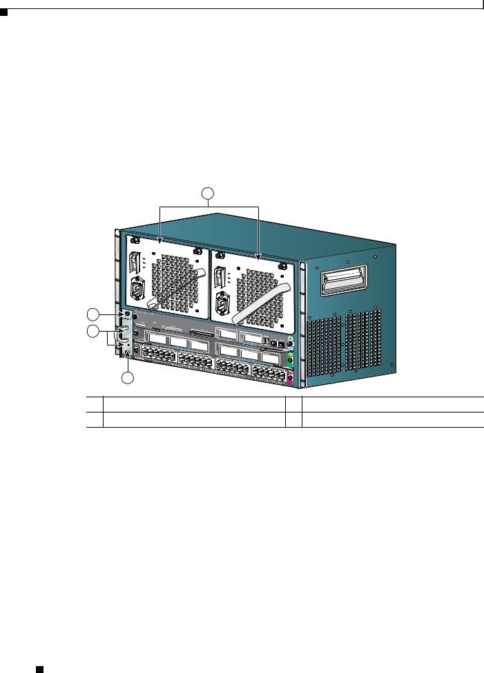
The Catalyst 4503-E switch (see Figure 1-1) is a three-slot switch designed for high-performance high-density wiring closet applications.
Figure 1-1 Catalyst 4503-E Switch (Front View)
4
3
|
4503 |
|
|
2 |
|
|
|
|
|
|
231362 |
|
1 |
|
|
1 |
Fan assembly |
3 |
Supervisor engine (Slot 1) |
2 |
Switching modules (Slots 2 and 3) |
4 |
Power supplies |
The Catalyst 4503-E switch supports the Supervisor Engine II+, Supervisor Engine II+TS, Supervisor Engine II+10GE, Supervisor Engine IV, Supervisor Engine V, Supervisor Engine V-10GE, and Supervisor Engine 6-E. The supervisor engine has a nonblocking, full-duplex, switching fabric that provides connections between the supervisor engine and the switching modules. Some supervisor engines use SFP modules for Gigabit Ethernet connections, or X2 modules for 10-Gigabit Ethernet connections. Refer to the installation note for your supervisor engine for more details on these modules.
Slot 1 is reserved for the supervisor engine only, which provides switching, local and remote management, and switch-status monitoring. Slots 2 and 3 are available for switching modules. The chassis will support up to 24 Gbps per slot for slots 2 and 3, for a maximum of 116 ports with a Supervisor Engine II+TS, or 96 ports and 2 uplinks for other supervisors.
Catalyst 4500 E-Series Switches Installation Guide
1-2 |
OL-13972-01 |
|
|

Chapter 1 Product Overview
Switch Features
Table 1-1 describes the features of the Catalyst 4503-E switch.
Table 1-1 Features of the Catalyst 4503 Switch
Feature |
Description |
|
|
Ethernet speeds |
• Ethernet (10BASE-T) interface to workstations and repeaters |
|
• Fast Ethernet (100BASE-T) interface to workstations, servers, switches, |
|
and routers |
|
Note Autonegotiation of link speed on each 10/100 port allows migration to |
|
100BASE-T from a 10BASE-T installed base. |
|
• Gigabit Ethernet (1000BASE-T and 1000BASE-X) interfaces for |
|
backbone interconnection of high-performance workstations, servers, |
|
switches and routers |
|
• 10-Gigabit Ethernet interfaces for backbone interconnection of |
|
high-performance switches and routers |
|
|
Standard equipment |
• Three-slot modular chassis with one slot reserved for a supervisor engine |
|
and two slots for switching modules |
|
• One hot-swappable fan assembly |
|
• Two power supply bays |
|
|
Power supplies |
• Supports a 1000 W, 1300 W, 1400 W, 2800 W, or 4200W AC-input power |
|
supply or a 1400 W DC-input single input or triple-input power supply1 |
|
• Optional redundant power supply |
|
|
Supervisor engine |
• Supports the WS-X4013+, WS-X4013+TS, WS-X4013+10GE, |
support |
WS-X4515, WS-X4516, WS-X4516-10GE, and WS-X45-Sup6-E |
|
supervisor engines |
|
• Holds the ASIC-based forwarding engine (data path) and the management |
|
processor and software (control path) |
|
• Features interface monitoring, environmental status, and SNMP and |
|
console/Telnet interface |
|
Note Packets are not forwarded while the module is removed; a system |
|
reboot occurs when a supervisor engine is reinserted. |
|
|
Switching module |
• 24-port 10/100BASE-TX Fast Ethernet switching module |
support |
(WS-X4124-RJ45) |
|
• 24-port 100BASE-FX Fast Ethernet switching module |
|
(WS-X4124-FX-MT) |
|
• 48-port 100BASE-FX Fast Ethernet switching module |
|
(WS-X4148-FX-MT) |
|
• 48-port 100BASE-LX10 Fast Ethernet switching module |
|
(WS-X4148-FE-LX-MT) |
|
• 48-port 10/100-Mbps Fast Ethernet switching module (WS-X4148-RJ) |
|
• 48-port 100BASE-BX10-D Fast Ethernet switching module |
|
(WS-X4148-FE-BD-LC) |
|
• 48-port 10/100-Mbps Fast Ethernet switching module (WS-X4148-RJ21) |
|
|
Catalyst 4500 E-Series Switches Installation Guide
|
OL-13972-01 |
1-3 |
|
|
|

Chapter 1 Product Overview
Switch Features
Table 1-1 Features of the Catalyst 4503 Switch (continued)
Feature |
Description |
Switching module |
• 48-port 100BASE-X Fast Ethernet switching module |
support (continued) |
(WS-X4248-FE-SFP) |
•24-port IEEE 802.3af-compliant PoE 10/100BASE-TX switching module (WS-X4224-RJ45V)
•48-port IEEE 802.3af compliant PoE 10/100BASE-TX RJ-45 switching module (WS-X4248-RJ45V)
•48 port IEEE 802.3af compliant PoE 10/100BASE-TX RJ-21 switching module (WS-X4248-RJ21V)
•32-port 10/100-Mbps Fast Ethernet plus 2-port Gigabit Ethernet switching module (WS-X4232-GB-RJ)
•32-port 10/100-Mbps Fast Ethernet plus 2-port 1000BASE-X Layer 3 Gigabit Ethernet routing module (WS-X4232-L3)
•32-port 10/100-Mbps Fast Ethernet switching module with modular uplink support (WS-X4232-RJ-XX)
–4-port MT-RJ uplink module (WS-U4504-FX-MT) (optional)
•2-port Gigabit Ethernet switching module (WS-X4302-GB)
•6-port 1000BASE-X Gigabit Ethernet switching module (WS-X4306-GB)
•6-port Gigabit Ethernet switching module (WS-X4506-GB-T)
•18-port Gigabit Ethernet switching module (WS-X4418-GB)
•24-port10/100/1000BASE-T GigabitEthernetswitching m odule (WS-X4424-GB-RJ45)
•48-port Gigabit Ethernet 1000 BASE LX (SPF) switching module (WS-X4448-GB-LX)
•48-port10/100/1000BASE-T GigabitEthernetswitching m odule (WS-X4448-GB-RJ45)
•24-port IEEE 802.3af-compliant PoE 10/100/1000BASE-T RJ-45 switching module (WS-X4524-GB-RJ45V)
•48-port10/100/1000BASE-T GigabitEthernetswitching m odule (WS-X4548-GB-RJ45)
•48-port Gigabit Ethernet switching module (WS-X4448-GB-SFP)
•48-port IEEE 802.3af compliant PoE 10/100/1000BASE-T Gigabit Ethernetswitching m odule (WS-X4548-GB-RJ45V)
•Backplane channel module (WS-X4019)
•6-port 10GbE X2 switching module (WS-X4606-X2-E)
•48-port 802.3af PoE 10/100/1000 RJ45 switching module (WS-X4648-RJ45V-E)
•48-port Premium PoE 10/100/1000 (RJ45) switching module (WS-X4648-RJ45V+E)
1.You will need to configure the 1400 W DC input current as appropriate for the model of switch. Refer to Appendix A, “Specifications.”
Catalyst 4500 E-Series Switches Installation Guide
1-4 |
OL-13972-01 |
|
|
Chapter 1 Product Overview
Switch Features
Catalyst 4506-E Switch Features
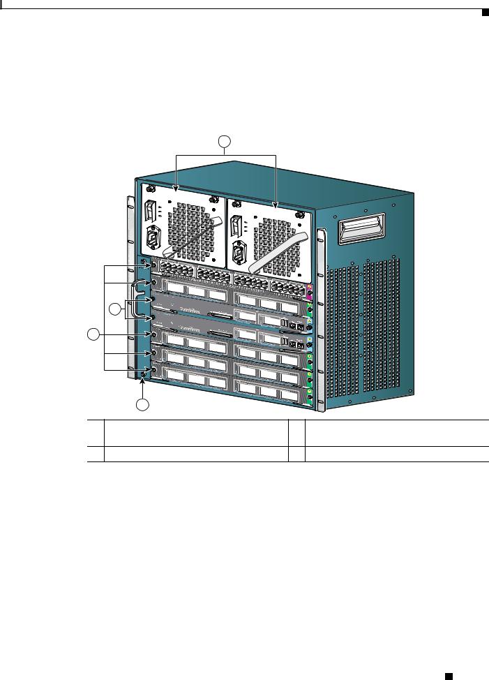
The Catalyst 4506-E switch (see Figure 1-2) is a six-slot switch designed for high-performance high-density wiring closet applications.
Figure 1-2 Catalyst 4506-E Switch (Front View)
4
3
2
4506
231363
1
1 |
Fan assembly |
3 |
Supervisor engine (Slot 1) |
|
|
|
|
2 |
Switching modules (Slots 2 to 6) |
4 |
Power supplies |
|
|
|
|
The Catalyst 4506-E switch supports the Supervisor Engine II+, Supervisor Engine II+10GE, Supervisor Engine IV, Supervisor Engine V, Supervisor Engine V-10GE, and Supervisor Engine 6-E. The supervisor engine has a nonblocking, full-duplex, switching fabric that provides connections between the supervisor engine and the switching modules. Some supervisor engines use SFP modules for Gigabit Ethernet connections, or X2 modules for 10-Gigabit Ethernet connections. Refer to the installation note for your supervisor engine for more details on these modules.
Slot 1 is reserved for the supervisor engine only, which provides switching, local and remote management, and switch-status monitoring. Slots 2 through 6 are available for switching modules. The chassis will support up to 24 Gbps per slot for slots 2 through 6, for a maximum of 240 ports and 2 uplinks.
Catalyst 4500 E-Series Switches Installation Guide
|
OL-13972-01 |
1-5 |
|
|
|

Chapter 1 Product Overview
Switch Features
Table 1-2 describes the features of the Catalyst 4506-E switch.
Table 1-2 |
Features of the Catalyst 4506-E Switch |
|
|
|
|
Feature |
Description |
|
|
|
|
Ethernet speeds |
• |
Ethernet (10BASE-T) interface to workstations and repeaters |
|
• |
Fast Ethernet (100BASE-T) interface to workstations, servers, switches, |
|
|
and routers |
Note Autonegotiation of link speed on each 10/100 port allows migration to 100BASE-T from a 10BASE-T installed base.
|
• Gigabit Ethernet (1000BASE-T and 1000BASE-X) interfaces for |
|
backbone interconnection of high-performance workstations, servers, |
|
switches and routers |
|
• 10-Gigabit Ethernet interfaces for backbone interconnection of |
|
high-performance switches and routers |
|
|
Standard equipment |
• Six-slot modular chassis with one slot reserved for a supervisor engine |
|
and five slots for switching modules |
|
• One hot-swappable fan assembly |
|
• Two power supply bays |
|
|
Power supplies |
• Supports a 1000 W, 1300 W, 1400 W, 2800 W, or 4200 W AC-input |
|
power supply or a 1400 W DC-input single or triple-input power supply1 |
|
• Optional redundant power supply |
|
|
Supervisor engine |
• Supports the WS-X4013+, WS-X4515, WS-X4516, WS-X4516-10GE, |
support |
and WS-X45-Sup6-E Supervisor Engines |
|
• Holds the ASIC-based forwarding engine (data path) and the |
|
management processor and software (control path) |
|
• Features interface monitoring, environmental status, and SNMP and |
|
console/Telnet interface |
|
Note Packets are not forwarded while the module is removed; a system |
|
reboot occurs when a supervisor engine is reinserted. |
|
|
Switching module |
• 24-port 10/100BASE-TX Fast Ethernet switching module |
support |
(WS-X4124-RJ45) |
|
• 24-port 100BASE-FX Fast Ethernet switching module |
|
(WS-X4124-FX-MT) |
|
• 48-port 100BASE-FX Fast Ethernet switching module |
|
(WS-X4148-FX-MT) |
|
• 48-port 100BASE-LX10 Fast Ethernet switching module |
|
(WS-X4148-FE-LX-MT) |
|
• 48-port 10/100-Mbps Fast Ethernet switching module (WS-X4148-RJ) |
|
• 48-port 100BASE-BX10-D Fast Ethernet switching module |
|
(WS-X4148-FE-BD-LC) |
Catalyst 4500 E-Series Switches Installation Guide
1-6 |
OL-13972-01 |
|
|

Chapter 1 Product Overview
Switch Features
Table 1-2 |
Features of the Catalyst 4506-E Switch (continued) |
||
|
|
|
|
Feature |
|
Description |
|
|
|
|
|
Switching module |
• |
48-port 10/100-Mbps Fast Ethernet switching module |
|
support (continued) |
|
(WS-X4148-RJ21) |
|
|
|
• 24-port IEEE 802.3af-compliant PoE 10/100BASE-TX switching |
|
|
|
|
module (WS-X4224-RJ45V) |
|
|
• 48-port IEEE 802.3af compliant PoE 10/100BASE-TX RJ-45 switching |
|
|
|
|
module (WS-X4248-RJ45V) |
|
|
• 48-port 100BASE-X Fast Ethernet switching module |
|
|
|
|
(WS-X4248-FE-SFP) |
|
|
• 48 port IEEE 802.3af compliant PoE 10/100BASE-TX RJ-21 switching |
|
|
|
|
module (WS-X4248-RJ21V) |
|
|
• 32-port 10/100-Mbps Fast Ethernet plus 2-port Gigabit Ethernet |
|
|
|
|
switching module (WS-X4232-GB-RJ) |
|
|
• 32-port 10/100-Mbps Fast Ethernet plus 2-port 1000BASE-X Layer 3 |
|
|
|
|
Gigabit Ethernet routing module (WS-X4232-L3) |
|
|
• 32-port 10/100-Mbps Fast Ethernet switching module with modular |
|
|
|
|
uplink support (WS-X4232-RJ-XX) |
|
|
• 2-port Gigabit Ethernet switching module (WS-X4302-GB) |
|
|
|
• 6-port 1000BASE-X Gigabit Ethernet switching module |
|
|
|
|
(WS-X4306-GB) |
|
|
• 6-port Gigabit Ethernet switching module (WS-X4506-GB-T) |
|
|
|
• 18-port Gigabit Ethernet switching module (WS-X4418-GB) |
|
|
|
• |
24-port10/100/1000BASE-T GigabitEthernetswitching m odule |
|
|
|
(WS-X4424-GB-RJ45) |
|
|
• 48-port Gigabit Ethernet 1000 BASE LX (SPF) switching module |
|
|
|
|
(WS-X4448-GB-LX) |
|
|
• |
48-port10/100/1000BASE-T GigabitEthernetswitching m odule |
|
|
|
(WS-X4448-GB-RJ45) |
|
|
• 24-port IEEE 802.3af-compliant PoE 10/100/1000BASE-T RJ-45 |
|
|
|
|
switching module (WS-X4524-GB-RJ45V) |
|
|
• |
48-port10/100/1000BASE-T GigabitEthernetswitching m odule |
|
|
|
(WS-X4548-GB-RJ45) |
|
|
• 48-port Gigabit Ethernet switching module (WS-X4448-GB-SFP) |
|
|
|
• 48-port IEEE 802.3af compliant PoE 10/100/1000BASE-T Gigabit |
|
|
|
|
Ethernetswitching m odule (WS-X4548-GB-RJ45V) |
|
|
• Backplane channel module (WS-X4019) |
|
|
|
• 6-port 10GbE X2 switching module (WS-X4606-X2-E) |
|
|
|
• 48-port 802.3af PoE 10/100/1000 RJ45 switching module |
|
|
|
|
(WS-X4648-RJ45V-E) |
|
|
• 48-port Premium PoE 10/100/1000 RJ45 switching module |
|
|
|
|
(WS-X4648-RJ45V+E) |
|
|
|
|
Catalyst 4500 E-Series Switches Installation Guide
|
OL-13972-01 |
1-7 |
|
|
|

Chapter 1 Product Overview
Switch Features
1.You will need to configure the 1400 W DC input current as appropriate for the model of switch. Refer to Appendix A, “Specifications.”
Supervisor Engine Redundancy
The Catalyst 4507R-E and Catalyst 4510R-E switches support supervisor engine redundancy. Redundancy allows a second supervisor engine to take over if the active supervisor engine fails.
With supervisor engine redundancy enabled, if the active supervisor engine fails or if a manual switchover is performed, the redundant supervisor engine becomes the active supervisor engine. The redundant supervisor engine is automatically initialized with the startup configuration of the active supervisor engine. Depending on the configuration this shortens the switchover time from 30 seconds or longer in Route Processor Redundancy (RPR) mode, to less than a second in Stateful Switch Over (SSO) mode.
In addition to the reduced switchover time, supervisor engine redundancy supports these:
•Online insertion and removal (OIR) of the redundant supervisor engine
Supervisor engine redundancy allows OIR of the redundant supervisor engine for maintenance. When the redundant supervisor engine is inserted, the active supervisor engine detects it. The redundant supervisor engine boots into a partially initialized state in RPR mode and a fully initialized state in SSO mode.
•Software upgrade
Load the new image on the redundant supervisor engine and conduct a switchover. This minimizes downtime during software changes on the supervisor engine.
When power is first applied to a switch, the supervisor engine that boots first becomes the active supervisor engine and remains active until a switchover occurs.
Redundancy requires that both supervisor engines in the chassis are of the same supervisor engine model, and that they use the same Cisco IOS software image.
For more detail about redundancy, refer to the Configuring Supervisor Engine Redundancy Using RPR and SSO chapter of the software configuration guide for your software release.
Catalyst 4500 E-Series Switches Installation Guide
1-8 |
OL-13972-01 |
|
|
Chapter 1 Product Overview
Switch Features
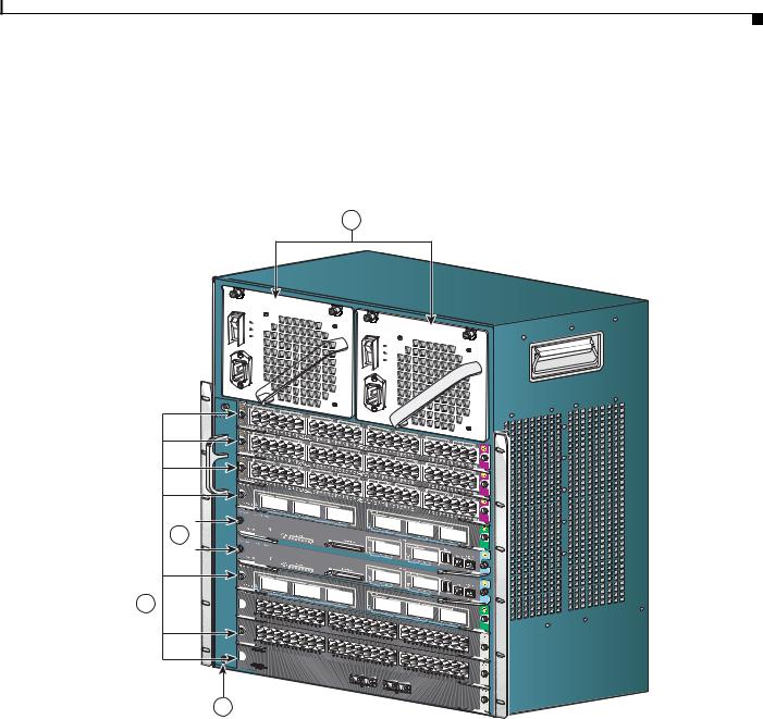
Catalyst 4507R-E Switch Features
The Catalyst 4507R-E switch (see Figure 1-3) is a seven-slot switch designed for high-performance high-density wiring closet applications.
Figure 1-3 Catalyst 4507R-E Switch (Front View)
4
4506 |
3 |
2 |
|
|
|
231952 |
|
1 |
|
|
1 |
Fan Tray |
3 |
Supervisor engines (primary in slot 3, |
|
|
|
secondary in slot 4) |
2 |
Switching modules (slots 1, 2, 5, 6, 7) |
4 |
Power supplies |
The Catalyst 4507R-E switch supports the Supervisor Engine II+, Supervisor Engine IV, Supervisor Engine V, Supervisor Engine V-10GE, and Supervisor Engine 6-E. The supervisor engine has two Gigabit Ethernet ports and a nonblocking, full-duplex, switching fabric that provides connections between the supervisor engine and the switching modules. Some supervisor engines use SFP modules for Gigabit Ethernet connections or X2 modules for 10-Gigabit Ethernet connections. Refer to the installation note for your supervisor engine for more details on these modules.
Slot 3 is reserved for the supervisor engine only, which provides switching, local and remote management, and switch-status monitoring. Slot 4 is reserved for a redundant supervisor engine only. Slots 1, 2, 5, 6, and 7 are available for switching modules and provide 24 Gbps per slot for a maximum of 240 ports and 4 uplinks.
Catalyst 4500 E-Series Switches Installation Guide
|
OL-13972-01 |
1-9 |
|
|
|

Chapter 1 Product Overview
Switch Features
Table 1-3 describes the features of the Catalyst 4507R-E switch.
Table 1-3 Features of the Catalyst 4507R-E Switch
Feature |
Description |
|
|
Ethernet speeds |
• Ethernet (10BASE-T) interface to workstations and repeaters |
|
• Fast Ethernet (100BASE-T) interface to workstations, servers, switches, and |
|
routers |
|
Note Autonegotiation of link speed on each 10/100 port allows migration to |
|
100BASE-T from a 10BASE-T installed base. |
|
• Gigabit Ethernet (1000BASE-T and 1000BASE-X) interfaces for backbone |
|
interconnection of high-performance switches and routers |
|
• 10-Gigabit Ethernet interfaces for backbone interconnection of |
|
high-performance switches and routers |
|
|
Standard equipment |
• Seven-slot modular chassis with one slot reserved for a supervisor engine, |
|
one slot reserved for a redundant supervisor engine, and five slots for |
|
switching modules |
|
• Two power supply bays |
|
• One hot-swappable fan assembly |
|
|
Power supplies |
• Can support a 1000 W, 1300 W, 1400 W, 2800 W, or 4200W AC-input power |
|
supply or a 1400 W DC-input single or triple-input power supply1 |
|
• Optional redundant power supply |
|
|
Supervisor engine |
• Supports the WS-X4013+, WS-X4515, WS-X4516, WS-X4516-10GE, and |
support |
WS-X45-Sup6-E Supervisor Engines |
|
• Holds the ASIC-based forwarding engine (data path) and the management |
|
processor and software (control path) |
|
• Features interface monitoring, environmental status, and SNMP and |
|
console/Telnet interface |
|
Note With a single supervisor, packets are not forwarded while the module is |
|
removed; a system reboot occurs when a supervisor engine is reinserted. |
|
In redundant systems, removing the active supervisor causes the standby |
|
supervisor to become active. |
|
|
|
Catalyst 4500 E-Series Switches Installation Guide |
1-10 |
OL-13972-01 |

Chapter 1 Product Overview
Switch Features
Table 1-3 |
Features of the Catalyst 4507R-E Switch (continued) |
|
|
|
|
Feature |
|
Description |
|
|
|
Switching module |
• 32-port 10/100-Mbps Fast Ethernet plus 2-port Gigabit Ethernet switching |
|
support |
|
module (WS-X4232-GB-RJ) |
|
|
• 32-port 10/100-Mbps Fast Ethernet plus 2-port 1000BASE-X Layer 3 |
|
|
Gigabit Ethernet routing module (WS-X4232-L3) |
|
|
• 32-port 10/100-Mbps Fast Ethernet switching module with modular uplink |
|
|
support (WS-X4232-RJ-XX) |
|
|
– 4-port MT-RJ uplink module (WS-U4504-FX-MT) (optional) |
|
|
• 2-port Gigabit Ethernet switching module (WS-X4302-GB) |
|
|
• 24-port 10/100BASE-TX Fast Ethernet switching module |
|
|
(WS-X4124-RJ45) |
|
|
• 24-port 100BASE-FX Fast Ethernet switching module (WS-X4124-FX-MT) |
|
|
• 48-port 100BASE-FX Fast Ethernet switching module (WS-X4148-FX-MT) |
|
|
• 48-port 100BASE-LX10 Fast Ethernet switching module |
|
|
(WS-X4148-FE-LX-MT) |
|
|
• 48-port 10/100-Mbps Fast Ethernet switching module (WS-X4148-RJ) |
|
|
• 48-port 100BASE-BX10-D Fast Ethernet switching module |
|
|
(WS-X4148-FE-BD-LC) |
|
|
• 48-port 10/100-Mbps Fast Ethernet switching module (WS-X4148-RJ21) |
|
|
• 48-port 100BASE-X Fast Ethernet switching module (WS-X4248-FE-SFP) |
|
|
|
|
|
Catalyst 4500 E-Series Switches Installation Guide |
|
|
|
|
|
|
|||
|
OL-13972-01 |
|
|
1-11 |
|
|
|
|
|
||

Chapter 1 Product Overview
Switch Features
Table 1-3 |
Features of the Catalyst 4507R-E Switch (continued) |
|
|
|
|
Feature |
|
Description |
|
|
|
Switching module |
• 24-port IEEE 802.3af-compliant PoE 10/100BASE-TX switching module |
|
support (continued) |
(WS-X4224-RJ45V) |
|
•48-port IEEE 802.3af compliant PoE 10/100BASE-TX RJ-45 switching module (WS-X4248-RJ45V)
•48 port IEEE 802.3af compliant PoE 10/100BASE-TX RJ-21 switching module (WS-X4248-RJ21V)
•6-port 1000BASE-X Gigabit Ethernet switching module (WS-X4306-GB)
•6-port Gigabit Ethernet switching module (WS-X4506-GB-T)
•18-port Gigabit Ethernet switching module (WS-X4418-GB)
•24-port10/100/1000BASE-T GigabitEthernetswitching m odule (WS-X4424-GB-RJ45)
•48-port Gigabit Ethernet 1000 BASE LX (SPF) switching module (WS-X4448-GB-LX)
•48-port10/100/1000BASE-T GigabitEthernetswitching m odule (WS-X4448-GB-RJ45)
•24-port IEEE 802.3af-compliant PoE 10/100/1000BASE-T RJ-45 switching module (WS-X4524-GB-RJ45V)
•48-port10/100/1000BASE-T GigabitEthernetswitching m odule (WS-X4548-GB-RJ45)
•48-port Gigabit Ethernet switching module (WS-X4448-GB-SFP)
•48-port IEEE 802.3af compliant PoE 10/100/1000BASE-T GigabitEthernet switching m odule (WS-X4548-GB-RJ45V)
•6-port 10GbE X2 switching module (WS-X4606-X2-E)
•48-port 802.3af PoE 10/100/1000 RJ45 switching module (WS-X4648-RJ45V-E)
•48-port Premium PoE 10/100/1000 RJ45 switching module (WS-X4648-RJ45V+E)
1.You will need to configure the 1400 W DC input current as appropriate for the model of switch. Refer to Appendix A, “Specifications.”
|
Catalyst 4500 E-Series Switches Installation Guide |
1-12 |
OL-13972-01 |
Chapter 1 Product Overview
Switch Features
Catalyst 4510R-E Switch Features
The Catalyst 4510R-E switch (see Figure 1-4) is a ten-slot switch designed for high-performance high-density wiring closet applications.
Figure 1-4 Catalyst 4510R-E Switch (Front View)
4
4506
3 
2 
 STATUS
STATUS
1
1 |
231953 |
2
1 |
Fan Tray |
3 |
Supervisor engines (primary in slot 5, |
|
|
|
secondary in slot 6) |
|
|
|
|
2 |
Switching modules (slots 1, 2, 3, 4, 7, 8, 9, 10) |
4 |
Power supplies |
|
|
|
|
The Catalyst 4510R-E switch supports the Supervisor Engine V, Supervisor Engine V-10GE, and Supervisor Engine 6-E. The supervisor engine has a nonblocking, full-duplex, switching fabric that provides connections between the supervisor engine and the switching modules. Some supervisor engines use SFP modules for Gigabit Ethernet connections, or X2 modules for 10 Gigabit Ethernet connections. Refer to the installation note for your supervisor engine for more details on these modules.
Slot 5 is reserved for the supervisor engine only, which provides switching, local and remote management, and switch-status monitoring. Slot 6 is reserved for a redundant supervisor engine only. Slots 1, 2, 3, 4, 7, 8, 9, and 10 are available for switching modules and provide up to 24 Gbps per slot
|
|
Catalyst 4500 E-Series Switches Installation Guide |
|
|
|
|
|
|
|||
|
OL-13972-01 |
|
|
1-13 |
|
|
|
|
|
||

Chapter 1 Product Overview
Switch Features
for a maximum of 384 ports and 4 uplinks. With a Supervisor Engine 6-E, slots 8 to 10 provide 6 Gbps per slot and all other slots provide 24 Gbps per slot. With a Supervisor Engine V or Supervisor Engine V-10GE, all slots are 6 Gbps and E-series switching modules can not be used.
Table 1-4 describes the features of the Catalyst 4510R-E switch.
Table 1-4 Features of the Catalyst 4510R-E Switch
Feature |
Description |
|
|
Ethernet speeds |
• Ethernet (10BASE-T) interface to workstations and repeaters |
|
• Fast Ethernet (100BASE-T) interface to workstations, servers, switches, and |
|
routers |
|
Note Autonegotiation of link speed on each 10/100 port allows migration to |
|
100BASE-T from a 10BASE-T installed base. |
|
• Gigabit Ethernet (1000BASE-T and 1000BASE-X) interfaces for backbone |
|
interconnection of high-performance switches and routers |
|
• 10-Gigabit Ethernet interfaces for backbone interconnection of |
|
high-performance switches and routers |
|
|
Standard equipment |
• Ten-slot modular chassis with one slot reserved for a supervisor engine, one |
|
slot reserved for a redundant supervisor engine, and eight slots for switching |
|
modules |
|
• Two power supply bays |
|
• One hot-swappable fan assembly |
|
|
Power supplies |
• Can support a 1400 W, 2800 W, or 4200 W AC-input power supply or a |
|
1400 W DC-input single or triple-input power supply1, 2 |
|
• Optional redundant power supply |
|
|
Supervisor engine |
• Supports the WS-X4516, WS-X4516-10GE, and WS-X45-Sup6-E |
support |
Supervisor Engines |
|
• Holds the ASIC-based forwarding engine (data path) and the management |
|
processor and software (control path) |
|
• Features interface monitoring, environmental status, and SNMP and |
|
console/Telnet interface |
|
Note With a single supervisor, packets are not forwarded while the module is |
|
removed; a system reboot occurs when a supervisor engine is reinserted. |
|
In redundant systems, removing the active supervisor causes the standby |
|
supervisor to become active. |
|
|
|
Catalyst 4500 E-Series Switches Installation Guide |
1-14 |
OL-13972-01 |
Loading...