


 Loading...
Getting Started Guide
Getting Started Guide for the Catalyst Express 500 Switches
INCLUDING LICENSE AND WARRANTY
1 |
2 |
4 |
|
|
|
|
|
|
|
|
|
|
|
|
|
|
1X |
3 |
6 |
|
|
|
|
|
|
|
|
|
|
|
|
|
|
|
|
5 |
8 |
|
|
|
|
|
|
|
|
|
|
|
|
|
|
|
|
7 |
10 |
|
|
|
|
|
|
|
|
|
|
|
|
|
|
|
|
9 |
12 |
|
|
|
|
|
|
|
|
|
|
|
|
|
|
|
|
11 |
|
|
|
|
|
|
|
|
|
|
|
|
|
|
|
|
|
11X |
13X |
13 |
14 |
16 |
|
|
|
|
|
|
|
|
|
|
|
|
|
|
15 |
17 |
18 |
20 |
|
|
|
||
|
|
|
|
|
|
|
|
|
|
|
19 |
22 |
|
|
||
2X |
|
|
|
|
|
|
|
|
|
|
|
|
21 |
23 |
24 |
|
POWER |
ETHERNET |
|
|
|
|
|
|
|
|
|
|
|
23X |
|
||
|
|
|
|
|
|
12X |
14X |
|
|
|
|
|
|
|
|
|
|
|
|
|
|
|
|
|
|
|
|
|
|
|
|
24X |
25 |
|
|
|
|
|
|
|
|
|
|
|
|
|
|
|
|
25 |
Catalyst |
Express |
500 |
|
|
|
SERIES |
|
26 |
|
SYSTEM |
|
|
ALERT |
|
|
26 |
|
PoE |
|
|
SETUP |
|
|
About this guide
This guide explains how to configure a Catalyst Express 500 switch for the first time. Basic configuration involves assigning network settings and a password to the switch.
After you complete the basic configuration, you can access the internal device manager application to manage and customize the switch. The device manager is an easy-to-use interface that provides tools for configuring, monitoring, and problem solving.
Before you begin
Before you power or install the switch, review the safety information in the Regulatory Compliance and Safety Information for the Catalyst Express 500 Switch that accompanies this guide.
For more information
For complete information about installing and using the switch, see the User Guide for the Catalyst Express 500 Switches online at Cisco.com > Technical Support & Documentation > Switches > Catalyst Express 500 Switches.
2
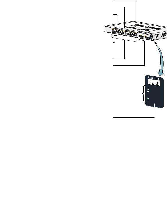
Quick tour
This illustration shows the Ethernet ports, LEDs, and other features on the switch. To set up the switch, you use the SETUP button, an Ethernet port, and the SYSTEM, SETUP, and port LEDs.
The model shown is a Catalyst Express 500-24LC. Your switch model might look slightly different.
AC power connector
Port LEDs 
Security cable slot side and rear panels
POWER |
ETHERNET |
|
Power over Ethernet (PoE) ports supply up to 15.4 W per port
Fast Ethernet ports
Dual-purpose uplink ports: SFP module and 10/100/1000BASE-T
Autonegotiate and auto-MDIX enabled on all ports
Switch LEDs: |
|
|
|
||
SYSTEM |
- switch status |
|
ALERT |
- events detected |
|
PoE |
- |
PoE status |
SETUP |
- |
setup mode |
Catalyst |
Express |
500 |
|
|
|
SERIES |
 SYSTEM
ALERT
PoE
SETUP 
SETUP button
3
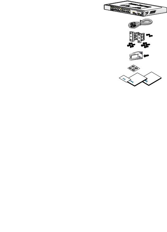
1 Unpack the box
Verify that you have received the items shown here. If any item is missing or damaged, contact your Cisco representative or reseller for instructions.
Switch
Power cord
Rack-mounting brackets and screws
Cable guide and screw
Mounting feet
Documentation
Catalyst |
Express 500 |
|
Card |
Documentation |
Documentation |
Cisco |
|
Cisco |
Cisco |
|
|
Equipment that you supply to set up the switch:
1.A PC with Windows 2000 or XP installed.
2.A web browser (Internet Explorer 5.5, 6.0, Netscape 7.1 or later) with JavaScript enabled.
3.A straight-through or crossover Category 5 Ethernet cable to connect your PC to the switch.
You should disable any pop-up blockers or proxy settings in your browser software and any wireless client running on your PC.
4
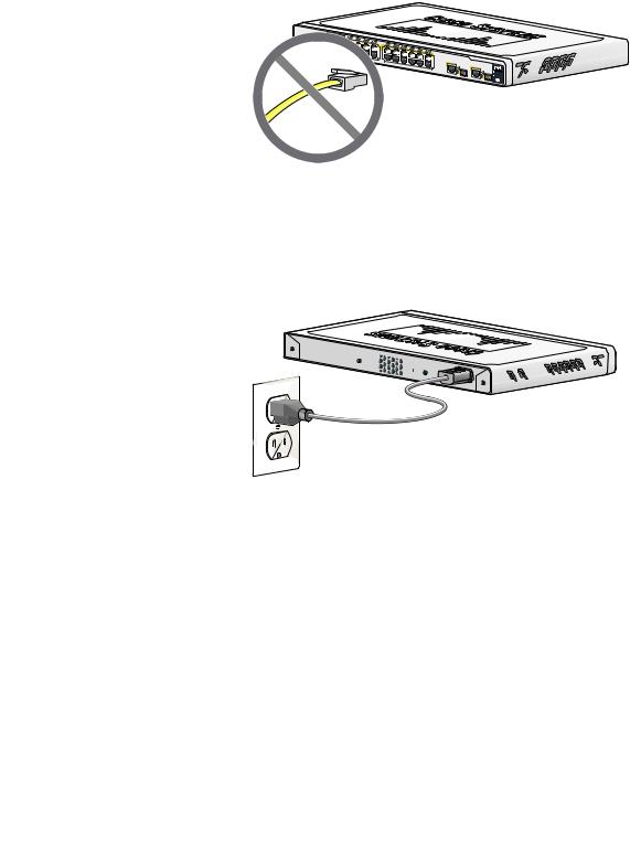
2 Make sure that nothing is connected to the switch
1 |
2 |
|
4 |
|
|
|
|
|
|
|
|
|
|
|
|
|
|
|
1X |
|
3 |
|
5 |
6 |
8 |
|
|
|
|
|
|
|
|
|
|
|
|
|
|
|
|
|
7 |
10 |
|
|
|
|
|
|
|
|
|
|
|
|
|
|
|
|
|
|
9 |
11 |
12 |
|
|
|
|
|
|
|
|
|
|
|
|
|
|
|
|
|
|
11X |
13X |
13 |
14 |
16 |
|
|
|
|
|
|
|
|
|
|
|
|
|
|
|
15 |
18 |
|
|
|
|
|
|||
2X |
|
|
|
|
|
|
|
|
|
|
|
17 |
19 |
20 |
22 |
|
|
|
|
|
|
|
|
|
|
|
|
|
|
|
|
21 |
23 |
24 |
|
||
POWER |
|
ETHERNET |
|
|
|
|
|
|
|
|
|
|
|
|
23X |
|
||
|
|
|
|
|
|
|
|
12X |
14X |
|
|
|
|
|
|
|
|
|
|
|
|
|
|
|
|
|
|
|
|
|
|
|
|
|
|
24X |
25 |
|
|
|
|
|
|
|
|
|
|
|
|
|
|
|
|
|
|
25 |
Catalyst |
Express 500 |
|
|
26 |
|
26 |
|
SERIES
3 Power the switch
Connect the AC power cord to the connector on the switch rear panel. Next, connect the power cord plug to a grounded AC outlet.
When the switch powers on, it begins the power-on self-test (POST), a series of automatic tests that confirm proper operation. POST lasts approximately 1 minute. During POST, the port and SYSTEM LEDs blink. When POST completes, the SYSTEM LED turns solid green.
5
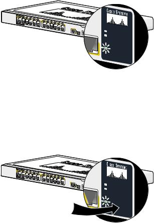
4 Wait for the SETUP LED to blink green
1 |
2 |
|
4 |
|
|
|
|
|
|
|
|
|
|
|
|
|
|
|
1X |
|
3 |
|
5 |
6 |
8 |
|
|
|
|
|
|
|
|
|
|
|
|
|
|
|
|
|
7 |
10 |
|
|
|
|
|
|
|
|
|
|
|
|
|
|
|
|
|
|
9 |
11 |
12 |
|
|
|
|
|
|
|
|
|
|
|
|
|
|
|
|
|
|
11X |
13X |
13 |
14 |
16 |
|
|
|
|
|
|
|
|
|
|
|
|
|
|
|
15 |
18 |
|
|
|
|
|
|||
2X |
|
|
|
|
|
|
|
|
|
|
|
17 |
19 |
20 |
22 |
|
|
|
|
|
|
|
|
|
|
|
|
|
|
|
|
21 |
23 |
24 |
|
||
POWER |
|
ETHERNET |
|
|
|
|
|
|
|
|
|
|
|
|
23X |
|
||
|
|
|
|
|
|
|
|
|
|
|
|
|
|
|
|
|||
|
|
|
|
|
|
|
|
12X |
14X |
|
|
|
|
|
|
|
|
|
|
|
|
|
|
|
|
|
|
|
|
|
|
|
|
|
|
24X |
25 |
|
|
|
|
|
|
|
|
|
|
|
|
|
|
|
|
|
|
25 |
Cisco 2960
 26 26
26 26
series
+PoE-4
 SYSTEM
ALERT
PoE
SETUP 
When POST has completed and the SYSTEM LED is solid green, the SETUP LED blinks green. The switch is ready to be configured. (If the SETUP LED stops blinking, you can still continue with the next step.)
5 Press the SETUP button
1 |
2 |
|
4 |
|
|
|
|
|
|
|
|
|
|
|
|
|
|
|
1X |
|
3 |
|
5 |
6 |
8 |
|
|
|
|
|
|
|
|
|
|
|
|
|
|
|
|
|
7 |
10 |
|
|
|
|
|
|
|
|
|
|
|
|
|
|
|
|
|
|
9 |
11 |
12 |
|
|
|
|
|
|
|
|
|
|
|
|
|
|
|
|
|
|
11X |
13X |
13 |
14 |
16 |
|
|
|
|
|
|
|
|
|
|
|
|
|
|
|
15 |
18 |
|
|
|
|
|
|||
2X |
|
|
|
|
|
|
|
|
|
|
|
17 |
19 |
20 |
22 |
|
|
|
|
|
|
|
|
|
|
|
|
|
|
|
|
21 |
23 |
24 |
|
||
POWER |
|
ETHERNET |
|
|
|
|
|
|
|
|
|
|
|
|
23X |
|
||
|
|
|
|
|
|
|
|
|
|
|
|
|
|
|
|
|||
|
|
|
|
|
|
|
|
12X |
14X |
|
|
|
|
|
|
|
|
|
|
|
|
|
|
|
|
|
|
|
|
|
|
|
|
|
|
24X |
25 |
|
|
|
|
|
|
|
|
|
|
|
|
|
|
|
|
|
|
25 |
Cisco 2960
 26 26
26 26
series
+PoE-4
 SYSTEM
ALERT
PoE
SETUP 
When you press the SETUP button, a switch port LED begins blinking green.
6

6 When a switch port LED blinks green, connect your PC to that port
1 |
2 |
|
4 |
1X |
|
3 |
|
2X |
|
|
|
POWER |
OVER |
ETHERNET |
|
Catalyst |
Express 500 |
|
SERIES
Connect one end of the Ethernet cable to the Ethernet port on your PC. Connect the other end to the switch port with the blinking LED. The port LEDs on your PC and the switch blink green while the switch configures the connection.
7 When the SETUP LED turns green, start a browser session on the PC
POWER |
ETHERNET |
Catalyst |
Express 500 |
|
SERIES
When you start a browser session on your PC, the set-up window automatically appears. If the window does not appear, check that any proxy settings or pop-up blockers are disabled on your browser and that any wireless client is disabled on your PC. You might also need to enter a URL in your browser, such as cisco.com, or another well-known website.
If you need help, see the “Troubleshooting” section on page 17.
7
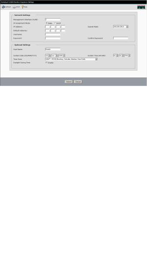
8 Enter the network settings
Network Settings |
Description |
|
|
Management |
We recommend using the default, VLAN 1. |
Interface |
The management VLAN establishes an IP |
(VLAN) |
connection to the switch. |
|
|
IP Assignment |
We recommend using the default, Static, |
Mode |
which means that the switch always has the |
|
IP address that you assign. |
|
Use the DHCP setting when you want the |
|
switch to automatically obtain an IP |
|
address from a DHCP server. |
|
|
IP Address |
Enter the IP address for the switch. (Later, |
|
you can use the IP address to access the |
|
switch through the device manager.) |
|
|
Subnet Mask |
Select a mask from the drop-down list. |
|
|
Default Gateway |
Enter the IP address of the router. |
|
|
Username |
Enter a unique name. |
|
|
8
Loading...