


 Loading...
Catalyst 6500 Series Supervisor Engine
Guide
July 2011
Americas Headquarters
Cisco Systems, Inc. 170 West Tasman Drive
San Jose, CA 95134-1706 USA http://www.cisco.com Tel: 408 526-4000
800 553-NETS (6387) Fax: 408 527-0883
Text Part Number: OL-7397-03
THE SPECIFICATIONS AND INFORMATION REGARDING THE PRODUCTS IN THIS MANUAL ARE SUBJECT TO CHANGE WITHOUT NOTICE. ALL STATEMENTS, INFORMATION, AND RECOMMENDATIONS IN THIS MANUAL ARE BELIEVED TO BE ACCURATE BUT ARE PRESENTED WITHOUT WARRANTY OF ANY KIND, EXPRESS OR IMPLIED. USERS MUST TAKE FULL RESPONSIBILITY FOR THEIR APPLICATION OF ANY PRODUCTS.
THE SOFTWARE LICENSE AND LIMITED WARRANTY FOR THE ACCOMPANYING PRODUCT ARE SET FORTH IN THE INFORMATION PACKET THAT SHIPPED WITH THE PRODUCT AND ARE INCORPORATED HEREIN BY THIS REFERENCE. IF YOU ARE UNABLE TO LOCATE THE SOFTWARE LICENSE OR LIMITED WARRANTY, CONTACT YOUR CISCO REPRESENTATIVE FOR A COPY.
The following information is for FCC compliance of Class A devices: This equipment has been tested and found to comply with the limits for a Class A digital device, pursuant to part 15 of the FCC rules. These limits are designed to provide reasonable protection against harmful interference when the equipment is operated in a commercial environment. This equipment generates, uses, and can radiate radio-frequency energy and, if not installed and used in accordance with the instruction manual, may cause harmful interference to radio communications. Operation of this equipment in a residential area is likely to cause harmful interference, in which case users will be required to correct the interference at their own expense.
The following information is for FCC compliance of Class B devices: The equipment described in this manual generates and may radiate radio-frequency energy. If it is not installed in accordance with Cisco’s installation instructions, it may cause interference with radio and television reception. This equipment has been tested and found to comply with the limits for a Class B digital device in accordance with the specifications in part 15 of the FCC rules. These specifications are designed to provide reasonable protection against such interference in a residential installation. However, there is no guarantee that interference will not occur in a particular installation.
Modifying the equipment without Cisco’s written authorization may result in the equipment no longer complying with FCC requirements for Class A or Class B digital devices. In that event, your right to use the equipment may be limited by FCC regulations, and you may be required to correct any interference to radio or television communications at your own expense.
You can determine whether your equipment is causing interference by turning it off. If the interference stops, it was probably caused by the Cisco equipment or one of its peripheral devices. If the equipment causes interference to radio or television reception, try to correct the interference by using one or more of the following measures:
•Turn the television or radio antenna until the interference stops.
•Move the equipment to one side or the other of the television or radio.
•Move the equipment farther away from the television or radio.
•Plug the equipment into an outlet that is on a different circuit from the television or radio. (That is, make certain the equipment and the television or radio are on circuits controlled by different circuit breakers or fuses.)
Modifications to this product not authorized by Cisco Systems, Inc. could void the FCC approval and negate your authority to operate the product.
The Cisco implementation of TCP header compression is an adaptation of a program developed by the University of California, Berkeley (UCB) as part of UCB’s public domain version of the UNIX operating system. All rights reserved. Copyright © 1981, Regents of the University of California.
NOTWITHSTANDING ANY OTHER WARRANTY HEREIN, ALL DOCUMENT FILES AND SOFTWARE OF THESE SUPPLIERS ARE PROVIDED “AS IS” WITH ALL FAULTS. CISCO AND THE ABOVE-NAMED SUPPLIERS DISCLAIM ALL WARRANTIES, EXPRESSED OR IMPLIED, INCLUDING, WITHOUT LIMITATION, THOSE OF MERCHANTABILITY, FITNESS FOR A PARTICULAR PURPOSE AND NONINFRINGEMENT OR ARISING FROM A COURSE OF DEALING, USAGE, OR TRADE PRACTICE.
IN NO EVENT SHALL CISCO OR ITS SUPPLIERS BE LIABLE FOR ANY INDIRECT, SPECIAL, CONSEQUENTIAL, OR INCIDENTAL DAMAGES, INCLUDING, WITHOUT LIMITATION, LOST PROFITS OR LOSS OR DAMAGE TO DATA ARISING OUT OF THE USE OR INABILITY TO USE THIS MANUAL, EVEN IF CISCO OR ITS SUPPLIERS HAVE BEEN ADVISED OF THE POSSIBILITY OF SUCH DAMAGES.
Cisco and the Cisco Logo are trademarks of Cisco Systems, Inc. and/or its affiliates in the U.S. and other countries. A listing of Cisco's trademarks can be found at www.cisco.com/go/trademarks. Third party trademarks mentioned are the property of their respective owners. The use of the word partner does not imply a partnership relationship between Cisco and any other company. (1005R)
Catalyst 6500 Series Supervisor Engine Guide
Copyright © 1999–2011 Cisco Systems, Inc. All rights reserved.
C O N T E N T S
|
Preface v |
|
|
|
|
|
|
Audience |
v |
|
|
|
|
|
Organization |
v |
|
|
|
|
|
Conventions |
vi |
|
|
|
|
|
Statement 1071—Warning Definition vii |
|||||
|
Related Documentation |
xiii |
||||
|
Catalyst 6500 Series Switch Chassis Overview 1-1 |
|||||
C H A P T E R 1 |
||||||
|
Catalyst 6503 Switch |
1-1 |
|
|||
|
Catalyst 6503-E |
1-2 |
|
|
||
|
Catalyst 6504-E |
1-3 |
|
|
||
|
Catalyst 6506 |
1-4 |
|
|
|
|
|
Catalyst 6506-E |
1-5 |
|
|
||
|
Catalyst 6509 |
1-6 |
|
|
|
|
|
Catalyst 6509-E |
1-7 |
|
|
||
|
Catalyst 6509-NEB |
1-8 |
|
|||
|
Catalyst 6509-NEB-A |
1-9 |
|
|||
|
Catalyst 6509-V-E |
1-10 |
|
|||
|
Catalyst 6513 |
1-11 |
|
|
||
|
Catalyst 6513-E |
1-12 |
|
|
||
|
Supervisor Engines |
|
|
|
||
C H A P T E R 2 |
2-1 |
|
|
|||
|
Supervisor Engine 2 |
2-1 |
|
|||
|
Supervisor Engine 32 |
2-7 |
|
|||
|
Supervisor Engine 32 PISA |
2-14 |
||||
|
Supervisor Engine 720 |
2-21 |
|
|||
|
Supervisor Engine 720-10GE |
2-26 |
||||
|
Supervisor Engine 2T |
2-33 |
|
|||
Catalyst 6500 Series Supervisor Engine Guide
|
OL-7397-03 |
iii |
|
Contents
C H A P T E R 3 |
Installing Supervisor Engines |
3-1 |
|
|
|
|
|||
|
|
Safety 3-1 |
|
|
|
|
|
|
|
|
|
Required Tools |
3-2 |
|
|
|
|
|
|
|
|
Installing a Supervisor Engine |
3-2 |
|
|
|
|
||
|
|
Removing a Supervisor Engine |
3-10 |
|
|
|
|
||
|
|
USB Console Port Driver Installation |
3-13 |
|
|
||||
|
|
Installing the Cisco Microsoft Windows USB Device Driver |
3-13 |
||||||
|
|
Uninstalling the Cisco Microsoft Windows USB Driver 3-15 |
|||||||
|
|
Installing Pluggable Transceivers 3-17 |
|
|
|
||||
|
|
Attaching the Network Interface Cables |
3-17 |
|
|
||||
|
|
Attaching Optical Network Interface Cables |
3-18 |
|
|||||
|
|
Mode-Conditioning Patch Cord |
3-18 |
|
|
|
|||
|
|
Connecting Transceivers to a Copper Network |
3-22 |
|
|||||
|
|
Where to Go Next 3-22 |
|
|
|
|
|
||
|
Pluggable Transceivers |
|
|
|
|
|
|
||
A P P E N D I X A |
A-1 |
|
|
|
|
|
|||
|
|
Port, Cable, and Connector Specifications |
|
|
|
||||
A P P E N D I X |
B |
B-1 |
|
|
|||||
|
|
Console Port |
B-1 |
|
|
|
|
|
|
|
|
Console Port Cables and Adapters B-1 |
|
|
|||||
|
|
CONSOLE PORT MODE Switch (Supervisor Engine 2 Only) |
B-2 |
||||||
|
|
Console Port Mode 2 Signaling and Pinouts |
B-5 |
|
|||||
|
|
Uplink Ports |
B-5 |
|
|
|
|
|
|
|
|
USB Ports B-7 |
|
|
|
|
|
|
|
|
|
Copper and Fiber-Optic Connectors |
B-7 |
|
|
|
|||
|
|
RJ-45 Connector |
B-7 |
|
|
|
|
|
|
|
|
Fiber-Optic Connectors |
B-8 |
|
|
|
|
||
|
|
ESD Precautions |
|
|
|
|
|
|
|
A P P E N D I X |
C |
C-1 |
|
|
|
|
|
|
|
|
|
Attaching Your ESD Grounding Strap |
C-1 |
|
|
|
|||
I N D E X
Catalyst 6500 Series Supervisor Engine Guide
|
iv |
OL-7397-03 |
|
|
|
Preface
This preface describes who should read the Catalyst 6500 Series Supervisor Engine Guide, how it is organized, and its document conventions.
Audience
Only trained and qualified service personnel (as defined in IEC 60950 and AS/NZS3260) should install, replace, or service the equipment described in this publication.
Organization
This publication is organized as follows:
Chapter |
Title |
Description |
|
|
|
Chapter 1 |
Catalyst 6500 Series |
Provides an overview of the Catalyst 6500 series |
|
Switch Chassis Overview |
switches. |
|
|
|
Chapter 2 |
Supervisor Engines |
Describes the Catalyst 6500 series supervisor engines. |
|
|
|
Chapter 3 |
Installing Supervisor |
Describes how to correctly and safely install supervisor |
|
Engines |
engines in the chassis. |
|
|
|
Appendix A |
Pluggable Transceivers |
Provides information on the pluggable transceivers |
|
|
supported by the supervisor engines. |
|
|
|
Appendix B |
Port, Cable, and |
Lists the cable specifications for the Catalyst 6500 |
|
Connector Specifications |
series supervisor engine ports. |
|
|
|
Appendix C |
ESD Precautions |
Describes ESD safety precautions that you need to |
|
|
follow when handling the supervisor engines. |
|
|
|
Catalyst 6500 Series Supervisor Engine Guide
|
OL-7397-03 |
v |
|
Preface
Conventions
Conventions
This publication uses the following conventions:
Convention |
Description |
|
|
|
|
boldface font |
Commands, command options, and keywords are in boldface. |
|
|
|
|
italic font |
Arguments for which you supply values are in italics. |
|
|
|
|
[ |
] |
Elements in square brackets are optional. |
|
|
|
{ x | y | z } |
Alternative keywords are grouped in braces and separated by vertical bars. |
|
|
|
|
[ x | y | z ] |
Optional alternative keywords are grouped in brackets and separated by |
|
|
|
vertical bars. |
|
|
|
string |
A nonquoted set of characters. Do not use quotation marks around the string |
|
|
|
or the string will include the quotation marks. |
|
|
|
screen font |
Terminal sessions and information the system displays are in screen font. |
|
|
|
|
boldface screen font |
Information you must enter is in boldface screen font. |
|
|
|
|
italic screen font |
Arguments for which you supply values are in italic screen font. |
|
|
|
|
^ |
|
The symbol ^ represents the key labeled Control. For example, the key |
|
|
combination ^D in a screen display means hold down the Control key while |
|
|
you press the D key. |
|
|
|
< |
> |
Nonprinting characters, such as passwords, are in angle brackets. |
|
|
|
Notes use the following conventions:
Note Means reader take note. Notes contain helpful suggestions or references to material not covered in the publication.
Cautions use the following conventions:
Caution Means reader be careful. In this situation, you might do something that could result in equipment damage or loss of data.
Catalyst 6500 Series Supervisor Engine Guide
|
vi |
OL-7397-03 |
|
|
|
Preface
Conventions
Warnings use the following conventions:
Statement 1071—Warning Definition
Warning IMPORTANT SAFETY INSTRUCTIONS
This warning symbol means danger. You are in a situation that could cause bodily injury. Before you work on any equipment, be aware of the hazards involved with electrical circuitry and be familiar with standard practices for preventing accidents. Use the statement number provided at the end of each warning to locate its translation in the translated safety warnings that accompanied this device. Statement 1071
SAVE THESE INSTRUCTIONS
Waarschuwing BELANGRIJKE VEILIGHEIDSINSTRUCTIES
Dit waarschuwingssymbool betekent gevaar. U verkeert in een situatie die lichamelijk letsel kan veroorzaken. Voordat u aan enige apparatuur gaat werken, dient u zich bewust te zijn van de bij elektrische schakelingen betrokken risico's en dient u op de hoogte te zijn van de standaard praktijken om ongelukken te voorkomen. Gebruik het nummer van de verklaring onderaan de waarschuwing als u een vertaling van de waarschuwing die bij het apparaat wordt geleverd, wilt raadplegen.
BEWAAR DEZE INSTRUCTIES
Varoitus TÄRKEITÄ TURVALLISUUSOHJEITA
Tämä varoitusmerkki merkitsee vaaraa. Tilanne voi aiheuttaa ruumiillisia vammoja. Ennen kuin käsittelet laitteistoa, huomioi sähköpiirien käsittelemiseen liittyvät riskit ja tutustu onnettomuuksien yleisiin ehkäisytapoihin. Turvallisuusvaroitusten käännökset löytyvät laitteen mukana toimitettujen käännettyjen turvallisuusvaroitusten joukosta varoitusten lopussa näkyvien lausuntonumeroiden avulla.
SÄILYTÄ NÄMÄ OHJEET
Attention IMPORTANTES INFORMATIONS DE SÉCURITÉ
Ce symbole d'avertissement indique un danger. Vous vous trouvez dans une situation pouvant entraîner des blessures ou des dommages corporels. Avant de travailler sur un équipement, soyez conscient des dangers liés aux circuits électriques et familiarisez-vous avec les procédures couramment utilisées pour éviter les accidents. Pour prendre connaissance des traductions des avertissements figurant dans les consignes de sécurité traduites qui accompagnent cet appareil, référez-vous au numéro de l'instruction situé à la fin de chaque avertissement.
CONSERVEZ CES INFORMATIONS
Catalyst 6500 Series Supervisor Engine Guide
|
OL-7397-03 |
vii |
|

Preface
Conventions
Warnung WICHTIGE SICHERHEITSHINWEISE
Dieses Warnsymbol bedeutet Gefahr. Sie befinden sich in einer Situation, die zu Verletzungen führen kann. Machen Sie sich vor der Arbeit mit Geräten mit den Gefahren elektrischer Schaltungen und den üblichen Verfahren zur Vorbeugung vor Unfällen vertraut. Suchen Sie mit der am Ende jeder Warnung angegebenen Anweisungsnummer nach der jeweiligen Übersetzung in den übersetzten Sicherheitshinweisen, die zusammen mit diesem Gerät ausgeliefert wurden.
BEWAHREN SIE DIESE HINWEISE GUT AUF.
Avvertenza IMPORTANTI ISTRUZIONI SULLA SICUREZZA
Questo simbolo di avvertenza indica un pericolo. La situazione potrebbe causare infortuni alle persone. Prima di intervenire su qualsiasi apparecchiatura, occorre essere al corrente dei pericoli relativi ai circuiti elettrici e conoscere le procedure standard per la prevenzione di incidenti. Utilizzare il numero di istruzione presente alla fine di ciascuna avvertenza per individuare le traduzioni delle avvertenze riportate in questo documento.
CONSERVARE QUESTE ISTRUZIONI
Advarsel VIKTIGE SIKKERHETSINSTRUKSJONER
Dette advarselssymbolet betyr fare. Du er i en situasjon som kan føre til skade på person. Før du begynner å arbeide med noe av utstyret, må du være oppmerksom på farene forbundet med elektriske kretser, og kjenne til standardprosedyrer for å forhindre ulykker. Bruk nummeret i slutten av hver advarsel for å finne oversettelsen i de oversatte sikkerhetsadvarslene som fulgte med denne enheten.
TA VARE PÅ DISSE INSTRUKSJONENE
Aviso INSTRUÇÕES IMPORTANTES DE SEGURANÇA
Este símbolo de aviso significa perigo. Você está em uma situação que poderá ser causadora de lesões corporais. Antes de iniciar a utilização de qualquer equipamento, tenha conhecimento dos perigos envolvidos no manuseio de circuitos elétricos e familiarize-se com as práticas habituais de prevenção de acidentes. Utilize o número da instrução fornecido ao final de cada aviso para localizar sua tradução nos avisos de segurança traduzidos que acompanham este dispositivo.
GUARDE ESTAS INSTRUÇÕES
¡Advertencia! INSTRUCCIONES IMPORTANTES DE SEGURIDAD
Este símbolo de aviso indica peligro. Existe riesgo para su integridad física. Antes de manipular cualquier equipo, considere los riesgos de la corriente eléctrica y familiarícese con los procedimientos estándar de prevención de accidentes. Al final de cada advertencia encontrará el número que le ayudará a encontrar el texto traducido en el apartado de traducciones que acompaña a este dispositivo.
GUARDE ESTAS INSTRUCCIONES
Catalyst 6500 Series Supervisor Engine Guide
|
viii |
OL-7397-03 |
|
|
|
Preface
Conventions
Varning! VIKTIGA SÄKERHETSANVISNINGAR
Denna varningssignal signalerar fara. Du befinner dig i en situation som kan leda till personskada. Innan du utför arbete på någon utrustning måste du vara medveten om farorna med elkretsar och känna till vanliga förfaranden för att förebygga olyckor. Använd det nummer som finns i slutet av varje varning för att hitta dess översättning i de översatta säkerhetsvarningar som medföljer denna anordning.
SPARA DESSA ANVISNINGAR
Catalyst 6500 Series Supervisor Engine Guide
|
OL-7397-03 |
ix |
|
Preface
Conventions
Aviso INSTRUÇÕES IMPORTANTES DE SEGURANÇA
Este símbolo de aviso significa perigo. Você se encontra em uma situação em que há risco de lesões corporais. Antes de trabalhar com qualquer equipamento, esteja ciente dos riscos que envolvem os circuitos elétricos e familiarize-se com as práticas padrão de prevenção de acidentes. Use o número da declaração fornecido ao final de cada aviso para localizar sua tradução nos avisos de segurança traduzidos que acompanham o dispositivo.
GUARDE ESTAS INSTRUÇÕES
Advarsel VIGTIGE SIKKERHEDSANVISNINGER
Dette advarselssymbol betyder fare. Du befinder dig i en situation med risiko for legemesbeskadigelse. Før du begynder arbejde på udstyr, skal du være opmærksom på de involverede risici, der er ved elektriske kredsløb, og du skal sætte dig ind i standardprocedurer til undgåelse af ulykker. Brug erklæringsnummeret efter hver advarsel for at finde oversættelsen i de oversatte advarsler, der fulgte med denne enhed.
GEM DISSE ANVISNINGER
Catalyst 6500 Series Supervisor Engine Guide
|
x |
OL-7397-03 |
|
|
|

Preface
Conventions
Catalyst 6500 Series Supervisor Engine Guide
|
OL-7397-03 |
xi |
|
Preface
Conventions
Catalyst 6500 Series Supervisor Engine Guide
|
xii |
OL-7397-03 |
|
|
|

Preface
Related Documentation
Related Documentation
For instructions on installing and configuring Catalyst 6500 series switches, refer to these publications:
•Regulatory Compliance and Safety Information for the Catalyst 6500 Series Switches
•Catalyst 6500 Series Module Guide
•Catalyst 6500 Series Switch Quick Software Configuration Guide
•Catalyst 6500 Series Switch Installation Guide
•Catalyst 6500 Series Switch Software Configuration Guide
•Catalyst 6500 Series Switch Command Reference
•Catalyst 6500 Series Switch Cisco IOS Software Configuration Guide
•Catalyst 6500 Series Switch Cisco IOS Command Reference
•Catalyst 6500 Series System Message Guide
•Installation Note for the CWDM Passive Optical System
•For information about MIBs, refer to the following World Wide Web site: http://www.cisco.com/public/sw-center/netmgmt/cmtk/mibs.shtml
Obtaining Documentation and Submitting a Service Request
For information on obtaining documentation, submitting a service request, and gathering additional information, see the monthly What’s New in Cisco Product Documentation, which also lists all new and revised Cisco technical documentation, at:
http://www.cisco.com/en/US/docs/general/whatsnew/whatsnew.html
Subscribe to the What’s New in Cisco Product Documentation as a Really Simple Syndication (RSS) feed and set content to be delivered directly to your desktop using a reader application. The RSS feeds are a free service and Cisco currently supports RSS version 2.0.
Catalyst 6500 Series Supervisor Engine Guide
|
OL-7397-03 |
xiii |
|

Preface
Related Documentation
Catalyst 6500 Series Supervisor Engine Guide
|
xiv |
OL-7397-03 |
|
|
|
C H A P T E R 1
Catalyst 6500 Series Switch Chassis Overview
Revised: July 2011
This chapter provides a brief overview of the Catalyst 6500 series switches. For details on the individual Catalyst 6500 series chassis, see the information listed on this page:
http://www.cisco.com/en/US/products/hw/switches/ps708/tsd_products_support_series_home.html
Note Throughout this publication, except where noted, the term supervisor engine is used to refer to Supervisor Engine 2, Supervisor Engine 32, Supervisor Engine 32 PISA, Supervisor Engine 720, Supervisor Engine 720-10GE, and the Supervisor Engine 2T.
Catalyst 6503 Switch
The Catalyst 6503 switch is a 3-slot (numbered from (1) top to (3) bottom), 4 RU, horizontal chassis that supports redundant power supplies and redundant supervisor engines. The chassis is NEBS L3 compliant. Supervisor engine support includes:
•Supervisor Engine 2, Supervisor Engine 32, Supervisor Engine 32 PISA, and Supervisor Engine 720 are supported.
Note Refer to your software release notes for specific information on the minimum software release versions required to support the supervisor engines in the Catalyst 6503 chassis.
• Supervisor engines must be installed in chassis slot 1 or slot 2.
Note Slots not occupied by supervisor engines can be used for modules. Check your software release notes for any restrictions on the type of module that can be installed.
•Supervisor Engine 720 has a built-in switching fabric. Switch Fabric Modules (WS-C6500-SFM and WS-X6500-SFM2) are not supported by Supervisor Engine 720. The Switch Fabric Modules and Supervisor Engine 720 cannot be installed in the same chassis.
•Supervisor Engine 32 and Supervisor Engine 32 PISA do not support the Switch Fabric Modules (WS-C6500-SFM and WS-X6500-SFM2). The Switch Fabric Modules and the Supervisor Engine 32 or the Supervisor Engine 32 PISA cannot be installed in the same chassis.
Catalyst 6500 Series Supervisor Engine Guide
|
OL-7397-03 |
1-1 |
|
|
|

Chapter 1 Catalyst 6500 Series Switch Chassis Overview
Catalyst 6503-E
•Supervisor Engine 32, Supervisor Engine 32 PISA, and the Supervisor Engine 720 require additional cooling. You must install the optional high-speed fan tray (FAN-MOD-3HS) in the chassis when any of these three supervisor engines are installed.
•The uplink ports are fully functional on the redundant supervisor engine when it is in standby mode.
Note In systems with redundant supervisor engines, both supervisor engines must be the same model and have the same daughter card configurations. Each supervisor engine must have the resources to run the switch on its own, which means that all supervisor engine resources are duplicated.
Identical supervisor engine memory configurations are recommended but are not required as long as the supervisor engine with the smaller memory configuration is sufficient to run the configured features of the switch. Additionally, each supervisor engine must have its own flash device and console port connections.
Additional information on the Catalyst 6503 switch chassis including data sheets and chassis installation is located at:
http://www.cisco.com/en/US/products/hw/switches/ps708/tsd_products_support_series_home.html
Catalyst 6503-E
The Catalyst 6503-E switch is an enhanced version of the Catalyst 6503 switch. The 3-slot (numbered from (1) top to (3) bottom), 4 RU, horizontal chassis supports redundant power supplies and redundant supervisor engines. It also supports a greater power capacity per slot than the Catalyst 6503 switch chassis and supports the WS-X67xx and WS-X68xx switching modules. The Catalyst 6503-E switch chassis is NEBS L3 compliant. Supervisor engine support and restrictions for the Catalyst 6503-E includes:
•Supervisor Engine 2, Supervisor Engine 32, Supervisor Engine 32 PISA, Supervisor Engine 720, Supervisor Engine 720-10GE, and Supervisor Engine 2T are supported.
Note Refer to your software release notes for specific information on the minimum software release versions required to support the supervisor engines in the Catalyst 6503-E chassis.
• Supervisor engines must be installed in slot 1 or slot 2.
Note Slots not occupied by supervisor engines can be used for modules. Check your software release notes for any restrictions on the type of module that can be installed.
•Supervisor Engine 720, Supervisor Engine 720-10GE, and Supervisor Engine 2T have a built-in switching fabric. The Switch Fabric Modules (WS-C6500-SFM and WS-X6500-SFM2) are not supported by Supervisor Engine 720 and Supervisor Engine 720-10GE and cannot be installed in the same chassis.
Catalyst 6500 Series Supervisor Engine Guide
1-2 |
OL-7397-03 |
|
|

Chapter 1 Catalyst 6500 Series Switch Chassis Overview
Catalyst 6504-E
•Supervisor Engine 32 and Supervisor Engine 32 PISA do not support the Switch Fabric Modules (WS-C6500-SFM and WS-X6500-SFM2) and cannot be installed in the same chassis.
•The uplink ports are fully functional on the redundant supervisor engine when it is in standby mode.
Note In systems with redundant supervisor engines, both supervisor engines must be the same model and have the same daughter card configurations. Each supervisor engine must have the resources to run the switch on its own, which means that all supervisor engine resources are duplicated.
Identical supervisor engine memory configurations are recommended but are not required as long as the supervisor engine with the smaller memory configuration is sufficient to run the configured features of the switch. Additionally, each supervisor engine must have its own flash device and console port connections.
Additional information on the Catalyst 6503-E switch chassis including data sheets and chassis installation is located at:
http://www.cisco.com/en/US/products/hw/switches/ps708/tsd_products_support_series_home.html
Catalyst 6504-E
The Catalyst 6504-E switch is an enhanced 4-slot (numbered from (1) top to (4) bottom), 5 RU, horizontal chassis that supports redundant power supplies and redundant supervisor engines. The Catalyst 6504-E switch chassis is NEBS L3 compliant. Supervisor engine support and restrictions for the Catalyst 6504-E includes:
•Supervisor Engine 2, Supervisor Engine 32, Supervisor Engine 32 PISA, Supervisor Engine 720, Supervisor Engine 720-10GE, and the Supervisor Engine 2T are supported.
Note Refer to your software release notes for specific information on the minimum software release versions required to support the supervisor engines in the Catalyst 6504-E chassis.
• Supervisor engines must be installed in slot 1 or slot 2.
Note Slots not occupied by supervisor engines can be used for modules. Check your software release notes for any restrictions on the type of module that can be installed.
•Supervisor Engine 720, Supervisor Engine 720-10GE, and Supervisor Engine 2T have a built-in switching fabric. Switch Fabric Modules (WS-C6500-SFM and WS-X6500-SFM2) are not supported by Supervisor Engine 720, Supervisor Engine 720-10GE, and Supervisor Engine 2T and cannot be installed in the same chassis.
Catalyst 6500 Series Supervisor Engine Guide
|
OL-7397-03 |
1-3 |
|
|
|

Chapter 1 Catalyst 6500 Series Switch Chassis Overview
Catalyst 6506
•Supervisor Engine 32 and Supervisor Engine 32 PISA do not support the Switch Fabric Modules (WS-C6500-SFM and WS-X6500-SFM2). The Switch Fabric Modules and Supervisor Engine 32 or Supervisor Engine 32 PISA cannot be installed in the same chassis.
•The uplink ports are fully functional on the redundant supervisor engine when it is in standby mode.
Note In systems with redundant supervisor engines, both supervisor engines must be the same model and have the same daughter card configurations. Each supervisor engine must have the resources to run the switch on its own, which means that all supervisor engine resources are duplicated.
Identical supervisor engine memory configurations are recommended but are not required as long as the supervisor engine with the smaller memory configuration is sufficient to run the configured features of the switch. Additionally, each supervisor engine must have its own flash device and console port connections.
Additional information on the Catalyst 6504-E switch chassis including data sheets and chassis installation is located at:
http://www.cisco.com/en/US/products/hw/switches/ps708/tsd_products_support_series_home.html
Catalyst 6506
The Catalyst 6506 switch is a 6-slot (numbered from (1) top to (6) bottom), 12 RU, horizontal chassis that supports redundant power supplies and redundant supervisor engines. The chassis is NEBS L3 compliant. Supervisor engine support and restrictions for the Catalyst 6506 includes:
•Supervisor Engine 2, Supervisor Engine 32, Supervisor Engine 32 PISA, Supervisor Engine 720, and Supervisor Engine 720-10GE are supported.
Note Refer to your software release notes for specific information on the minimum software release versions required to support the supervisor engines in the Catalyst 6506 chassis.
•Supervisor Engine 2 must be installed in slot 1 or slot 2.
•Supervisor Engine 32, Supervisor Engine 32 PISA, Supervisor Engine 720, and Supervisor Engine 720-10GE must be installed in slot 5 or slot 6.
Note Slots not occupied by supervisor engines can be used for modules. Check your software release notes for any restrictions on the type of module that can be installed.
•Supervisor Engine 32, Supervisor Engine 32 PISA, Supervisor Engine 720, and Supervisor Engine 720-10GE all require the high-speed fan tray (WS-C6K-6SLOT-FAN2) be installed in the chassis. You must also install a 2500 W or higher capacity power supply in the chassis to power the high-speed fan tray.
Note The 2500 W power supply, when supporting the high-speed fan tray, can be powered from either 120 VAC or 220 VAC.
•Supervisor Engine 720 and Supervisor Engine 720-10GE have a built-in switching fabric. Switch Fabric Modules (WS-C6500-SFM and WS-X6500-SFM2) are not supported by Supervisor Engine 720 and Supervisor Engine 720-10GE. The Switch Fabric Modules and Supervisor Engine 720 or Supervisor Engine 720-10GE cannot be installed in the same chassis.
Catalyst 6500 Series Supervisor Engine Guide
1-4 |
OL-7397-03 |
|
|

Chapter 1 Catalyst 6500 Series Switch Chassis Overview
Catalyst 6506-E
•Supervisor Engine 32 and Supervisor Engine 32 PISA do not support the Switch Fabric Modules (WS-C6500-SFM and WS-X6500-SFM2). The Switch Fabric Modules and Supervisor Engine 32 or Supervisor Engine 32 PISA cannot be installed in the same chassis.
•The uplink ports are fully functional on the redundant supervisor engine in standby mode.
Note In systems with redundant supervisor engines, both supervisor engines must be the same model and have the same daughter card configurations. Each supervisor engine must have the resources to run the switch on its own, which means all supervisor engine resources are duplicated.
Identical supervisor engine memory configurations are recommended but are not required as long as the supervisor engine with the smaller memory configuration is sufficient to run the configured features of the switch. Additionally, each supervisor engine must have its own flash device and console port connections.
Additional information on the Catalyst 6506 switch chassis including data sheets and chassis installation is located at:
http://www.cisco.com/en/US/products/hw/switches/ps708/tsd_products_support_series_home.html
Catalyst 6506-E
The Catalyst 6506-E switch is an enhanced version of the Catalyst 6506 switch. The 6-slot (numbered from (1) top to (6) bottom), 12 RU, horizontal chassis supports redundant power supplies and redundant supervisor engines. It also supports a greater power capacity per slot than the Catalyst 6506 switch chassis and supports the WS-X67xx and WS-X68xx switching modules. The Catalyst 6506-E switch chassis is NEBS L3 compliant. Supervisor engine support and restrictions for the Catalyst 6506-E includes:
•Supervisor Engine 2, Supervisor Engine 32, Supervisor Engine 32 PISA, Supervisor Engine 720, Supervisor Engine 720-10GE, and Supervisor Engine 2T are supported.
Note Refer to your software release notes for specific information on the minimum software release versions required to support the supervisor engines in the Catalyst 6506-E chassis.
•Supervisor Engine 2 must be installed in slot 1 or slot 2.
•Supervisor Engine 32, Supervisor Engine 32 PISA, Supervisor Engine 720, Supervisor Engine 720-10GE, and Supervisor Engine 2T must be installed in slot 5 or slot 6.
Note Slots not occupied by supervisor engines can be used for modules. Check your software release notes for any restrictions on the type of module that can be installed.
•Supervisor Engine 720, Supervisor Engine 720-10GE, Supervisor Engine 2T have a built-in switching fabric. Switch Fabric Modules (WS-C6500-SFM and WS-X6500-SFM2) are not supported by Supervisor Engine 720, Supervisor Engine 720-10GE, and Supervisor Engine 2T and cannot be installed in the same chassis.
Catalyst 6500 Series Supervisor Engine Guide
|
OL-7397-03 |
1-5 |
|
|
|

Chapter 1 Catalyst 6500 Series Switch Chassis Overview
Catalyst 6509
•Supervisor Engine 32 and Supervisor Engine 32 PISA do not support the Switch Fabric Modules (WS-C6500-SFM and WS-X6500-SFM2). The Switch Fabric Modules and Supervisor Engine 32 or Supervisor Engine 32 PISA cannot be installed in the same chassis.
•The uplink ports are fully functional on the redundant supervisor engine in standby mode.
Note In systems with redundant supervisor engines, both supervisor engines must be the same model and have the same daughter card configurations. Each supervisor engine must have the resources to run the switch on its own, which means all supervisor engine resources are duplicated.
Identical supervisor engine memory configurations are recommended but are not required as long as the supervisor engine with the smaller memory configuration is sufficient to run the configured features of the switch. Additionally, each supervisor engine must have its own flash device and console port connections.
Additional information on the Catalyst 6506-E switch chassis including data sheets and chassis installation is located at:
http://www.cisco.com/en/US/products/hw/switches/ps708/tsd_products_support_series_home.html
Catalyst 6509
The Catalyst 6509 switch is a 9-slot (numbered from (1) top to (9) bottom), 15 RU, horizontal chassis that supports redundant power supplies and redundant supervisor engines. The chassis is NEBS L3 compliant. Supervisor engine support and restrictions for the Catalyst 6509 includes:
•Supervisor Engine 2, Supervisor Engine 32, Supervisor Engine 32 PISA, Supervisor Engine 720, and Supervisor Engine 720-10GE are supported.
Note Refer to your software release notes for specific information on the minimum software release versions required to support the supervisor engines in the Catalyst 6509 chassis.
•Supervisor Engine 2 must be installed in slot 1 or slot 2.
•Supervisor Engine 32, Supervisor Engine 32 PISA, Supervisor Engine 720, and Supervisor Engine 720-10GE must be installed in slot 5 or slot 6.
Note Slots not occupied by supervisor engines can be used for modules. Check your software release notes for any restrictions on the type of module that can be installed.
•Supervisor Engine 32, Supervisor Engine 32 PISA, Supervisor Engine 720, and Supervisor Engine 720-10GE require that the high-speed fan tray (WS-C6K-9SLOT-FAN2) be installed in the chassis. You must also install a 2500 W or higher capacity power supply in the chassis to power the high-speed fan tray.
Note The 2500 W power supply, when supporting the high-speed fan tray, can be powered from either 120 VAC or 220 VAC.
•Supervisor Engine 720 and Supervisor Engine 720-10GE have a built-in switching fabric. Switch Fabric Modules (WS-C6500-SFM and WS-X6500-SFM2) are not supported by Supervisor Engine 720 and Supervisor Engine 720-10GE. The Switch Fabric Modules and Supervisor Engine 720 or Supervisor Engine 720-10GE cannot be installed in the same chassis.
Catalyst 6500 Series Supervisor Engine Guide
1-6 |
OL-7397-03 |
|
|
Chapter 1 Catalyst 6500 Series Switch Chassis Overview
Catalyst 6509-E
•Supervisor Engine 32 and Supervisor Engine 32 PISA do not support the Switch Fabric Modules (WS-C6500-SFM and WS-X6500-SFM2). The Switch Fabric Modules and Supervisor Engine 32 or Supervisor Engine 32 PISA cannot be installed in the same chassis.
•The uplink ports are fully functional on all redundant supervisor engine models when they are in standby mode.
Note In systems with redundant supervisor engines, both supervisor engines must be the same model and have the same daughter card configurations. Each supervisor engine must have the resources to run the switch on its own, which means all supervisor engine resources are duplicated.
Identical supervisor engine memory configurations are recommended but are not required as long as the supervisor engine with the smaller memory configuration is sufficient to run the configured features of the switch. Additionally, each supervisor engine must have its own flash device and console port connections.
Additional information on the Catalyst 6509 switch chassis including data sheets and chassis installation is located at:
http://www.cisco.com/en/US/products/hw/switches/ps708/tsd_products_support_series_home.html
Catalyst 6509-E
The Catalyst 6509-E switch is an enhanced version of the Catalyst 6509 switch. The 9-slot (numbered from (1) top to (9) bottom), 15 RU, horizontal chassis supports redundant power supplies and redundant supervisor engines. It also supports a greater power capacity per slot than the Catalyst 6509 switch chassis and supports the WS-X67xx and WS-X68xx switching modules. Supervisor engine support and restrictions for the Catalyst 6509-E includes:
•Supervisor Engine 2, Supervisor Engine 32, Supervisor Engine 32 PISA, Supervisor Engine 720, Supervisor Engine 720-10GE, and Supervisor Engine 2T are supported.
Note Refer to your software release notes for specific information on the minimum software release versions required to support the supervisor engines in the Catalyst 6509-E chassis.
•Supervisor Engine 2 must be installed in slot 1 or slot 2.
•Supervisor Engine 32, Supervisor Engine 32 PISA, Supervisor Engine 720, Supervisor Engine 720-10GE, and Supervisor Engine 2T must be installed in slot 5 or slot 6.
Note Slots not occupied by supervisor engines can be used for modules. Check your software release notes for any restrictions on the type of module that can be installed.
•Supervisor Engine 720, Supervisor Engine 720-10GE, and Supervisor Engine 2T have a built-in switching fabric. Switch Fabric Modules (WS-C6500-SFM and WS-X6500-SFM2) are not supported by Supervisor Engine 720, Supervisor Engine 720-10GE, and Supervisor Engine 2T and cannot be installed in the same chassis.
Catalyst 6500 Series Supervisor Engine Guide
|
OL-7397-03 |
1-7 |
|
|
|

Chapter 1 Catalyst 6500 Series Switch Chassis Overview
Catalyst 6509-NEB
•Supervisor Engine 32 and Supervisor Engine 32 PISA do not support the Switch Fabric Modules (WS-C6500-SFM and WS-X6500-SFM2). The Switch Fabric Modules and Supervisor Engine 32 or Supervisor Engine 32 PISA cannot be installed in the same chassis.
•The uplink ports are fully functional on all redundant supervisor engine models when they are in standby mode.
Note In systems with redundant supervisor engines, both supervisor engines must be the same model and have the same daughter card configurations. Each supervisor engine must have the resources to run the switch on its own, which means all supervisor engine resources are duplicated.
Identical supervisor engine memory configurations are recommended but are not required as long as the supervisor engine with the smaller memory configuration is sufficient to run the configured features of the switch. Additionally, each supervisor engine must have its own flash device and console port connections.
Additional information on the Catalyst 6509-E switch chassis including data sheets and chassis installation is located at:
http://www.cisco.com/en/US/products/hw/switches/ps708/tsd_products_support_series_home.html
Catalyst 6509-NEB
The Catalyst 6509-NEB switch is a 9-slot (numbered from (1) right to (9) left), 20 RU, vertical chassis that supports redundant power supplies and redundant supervisor engines. The chassis is NEBS L3 compliant. Supervisor engine support and restrictions for the Catalyst 6509-NEB includes:
•Supervisor Engine 2 is supported.
•Supervisor Engine 32, Supervisor Engine 32 PISA, Supervisor Engine 720, and Supervisor Engine 720-10GE are supported if the WS-6509-NEB-UPGRD kit is installed.
Note Refer to your software release notes for specific information on the minimum software release versions required to support the supervisor engines in the Catalyst 6509-NEBchassis.
•Supervisor Engine 2 must be installed in slot 1 or slot 2.
•Supervisor Engine 32, Supervisor Engine 32 PISA, Supervisor Engine 720, and Supervisor Engine 720-10GE must be installed in slot 5 or slot 6.
Note Slots not occupied by supervisor engines can be used for modules. Check your software release notes for any restrictions on the type of module that can be installed.
•Supervisor Engine 720 and Supervisor Engine 720-10GE have a built-in switching fabric. Switch Fabric Modules (WS-C6500-SFM and WS-X6500-SFM2) are not supported by Supervisor Engine 720 and Supervisor Engine 720-10GE. The Switch Fabric Modules and Supervisor Engine 720 or Supervisor Engine 720-10GE cannot be installed in the same chassis.
Catalyst 6500 Series Supervisor Engine Guide
1-8 |
OL-7397-03 |
|
|

Chapter 1 Catalyst 6500 Series Switch Chassis Overview
Catalyst 6509-NEB-A
•Supervisor Engine 32 and Supervisor Engine 32 PISA do not support the Switch Fabric Modules (WS-C6500-SFM and WS-X6500-SFM2). The Switch Fabric Modules and Supervisor Engine 32 or Supervisor Engine 32 PISA cannot be installed in the same chassis.
•The uplink ports are fully functional on all redundant supervisor engine models when they are in standby mode.
Note In systems with redundant supervisor engines, both supervisor engines must be the same model and have the same daughter card configurations. Each supervisor engine must have the resources to run the switch on its own, which means all supervisor engine resources are duplicated.
Identical supervisor engine memory configurations are recommended but are not required as long as the supervisor engine with the smaller memory configuration is sufficient to run the configured features of the switch. Additionally, each supervisor engine must have its own flash device and console port connections.
Additional information on the Catalyst 6509-NEB switch chassis including data sheets and chassis installation is located at:
http://www.cisco.com/en/US/products/hw/switches/ps708/tsd_products_support_series_home.html
Catalyst 6509-NEB-A
The Catalyst 6509-NEB-A switch is an enhanced version of the Catalyst 6509-NEB switch. The 9-slot (numbered from (1) right to (9) left), 21 RU, vertical chassis supports redundant power supplies and redundant supervisor engines. The Catalyst 6509-NEB-A switch chassis is NEBS L3 compliant. Supervisor engine support and restrictions for the Catalyst 6509-NEB-A includes:
•Supervisor Engine 2, Supervisor Engine 32, Supervisor Engine 32 PISA, Supervisor Engine 720, and Supervisor Engine 720-10GE are supported.
Note Refer to your software release notes for specific information on the minimum software release versions required to support the supervisor engines in the Catalyst 6509-NEB-A chassis.
•Supervisor Engine 2 must be installed in slot 1 or slot 2.
•Supervisor Engine 32, Supervisor Engine 32 PISA, Supervisor Engine 720, and Supervisor Engine 720-10GE must be installed in slot 5 or slot 6.
Note Slots not occupied by supervisor engines can be used for modules. Check your software release notes for any restrictions on the type of module that can be installed.
•Supervisor Engine 720 and Supervisor Engine 720-10GE have a built-in switching fabric. Switch Fabric Modules (WS-C6500-SFM and WS-X6500-SFM2) are not supported by Supervisor Engine 720 and Supervisor Engine 720-10GE. The Switch Fabric Modules and Supervisor Engine 720 or Supervisor Engine 720-10GE cannot be installed in the same chassis.
Catalyst 6500 Series Supervisor Engine Guide
|
OL-7397-03 |
1-9 |
|
|
|

Chapter 1 Catalyst 6500 Series Switch Chassis Overview
Catalyst 6509-V-E
•Supervisor Engine 32 and Supervisor Engine 32 PISA do not support the Switch Fabric Modules (WS-C6500-SFM and WS-X6500-SFM2). The Switch Fabric Modules and Supervisor Engine 32 or Supervisor Engine 32 PISA cannot be installed in the same chassis.
•The uplink ports are fully functional on all redundant supervisor engine models when they are in standby mode.
Note In systems with redundant supervisor engines, both supervisor engines must be the same model and have the same daughter card configurations. Each supervisor engine must have the resources to run the switch on its own, which means all supervisor engine resources are duplicated.
Identical supervisor engine memory configurations are recommended but are not required as long as the supervisor engine with the smaller memory configuration is sufficient to run the configured features of the switch. Additionally, each supervisor engine must have its own flash device and console port connections.
Additional information on the Catalyst 6509-NEB-A switch chassis including data sheets and chassis installation is located at:
http://www.cisco.com/en/US/products/hw/switches/ps708/tsd_products_support_series_home.html
Catalyst 6509-V-E
The Catalyst 6509-V-E switch is an enhanced version of the Catalyst 6509-NEB-A switch. The 9-slot (numbered from (1) right to (9) left), 21 RU, vertical chassis supports redundant power supplies, redundant supervisor engines, and redundant fan trays. It also supports a greater power capacity per slot than the Catalyst 6509-NEB-A switch chassis. The Catalyst 6509-V-E switch chassis is NEBS L3 compliant. Supervisor engine support and restrictions for the Catalyst 6509-V-E includes:
•Supervisor Engine 32, Supervisor Engine 32 PISA, Supervisor Engine 720, Supervisor Engine 720-10GE, and Supervisor Engine 2T are supported.
Note Refer to your software release notes for specific information on the minimum software release versions required to support the supervisor engines in the Catalyst 6509-NEB-A chassis.
•Supervisor Engine 32, Supervisor Engine 32 PISA, Supervisor Engine 720, Supervisor Engine 720-10GE, and Supervisor Engine 2T must be installed in slot 5 or slot 6.
Note Slots not occupied by supervisor engines can be used for modules. Check your software release notes for any restrictions on the type of module that can be installed.
•Supervisor Engine 720, Supervisor Engine 720-10GE, and Supervisor Engine 2T have a built-in switching fabric. Switch Fabric Modules (WS-C6500-SFM and WS-X6500-SFM2) are not supported by Supervisor Engine 720, Supervisor Engine 720-10GE, and Supervisor Engine 2T and cannot be installed in the same chassis.
Catalyst 6500 Series Supervisor Engine Guide
1-10 |
OL-7397-03 |
|
|

Chapter 1 Catalyst 6500 Series Switch Chassis Overview
Catalyst 6513
•Supervisor Engine 32 and Supervisor Engine 32 PISA do not support the Switch Fabric Modules (WS-C6500-SFM and WS-X6500-SFM2). The Switch Fabric Modules and Supervisor Engine 32 or Supervisor Engine 32 PISA cannot be installed in the same chassis.
•The uplink ports are fully functional on all redundant supervisor engine models when they are in standby mode.
Note In systems with redundant supervisor engines, both supervisor engines must be the same model and have the same daughter card configurations. Each supervisor engine must have the resources to run the switch on its own, which means all supervisor engine resources are duplicated.
Identical supervisor engine memory configurations are recommended but are not required as long as the supervisor engine with the smaller memory configuration is sufficient to run the configured features of the switch. Additionally, each supervisor engine must have its own flash device and console port connections.
Additional information on the Catalyst 6509-V-E switch chassis including data sheets and chassis installation is located at:
http://www.cisco.com/en/US/products/hw/switches/ps708/tsd_products_support_series_home.html
Catalyst 6513
The Catalyst 6513 switch is a 13-slot (numbered from (1) top to (13) bottom), 20 RU, horizontal chassis that supports redundant power supplies and redundant supervisor engines. The chassis is NEBS L3 compliant. Supervisor engine support and restrictions for the Catalyst 6513 includes:
•Supports Supervisor Engine 2, Supervisor Engine 32, Supervisor Engine 32 PISA, Supervisor Engine 720, and Supervisor Engine 720-10GE.
Note Refer to your software release notes for specific information on the minimum software release versions required to support the supervisor engines in the Catalyst 6513 chassis.
•Supervisor Engine 2 must be installed in slot 1 or slot 2.
•Supervisor Engine 32, Supervisor Engine 32 PISA, Supervisor Engine 720, and Supervisor Engine 720-10GE must be installed in slot 7 or slot 8.
Note Slots not occupied by supervisor engines can be used for modules. Check your software release notes for any restrictions on the type of module that can be installed.
•Supervisor Engine 32, Supervisor Engine 32 PISA, Supervisor Engine 720, and Supervisor Engine 720-10GE require additional cooling. You must install the high-speed fan tray (WS-C6K-13SLT-FAN2) when using any of these supervisor engines. You must also install a 2500 W or higher capacity power supply in the chassis to power the high-speed fan tray.
•Supervisor Engine 720 and Supervisor Engine 720-10GE have a built-in switching fabric. Switch Fabric Modules (WS-C6500-SFM and WS-X6500-SFM2) are not supported by Supervisor Engine 720 and Supervisor Engine 720-10GE. The Switch Fabric Modules and Supervisor Engine 720 or Supervisor Engine 720-10GE cannot be installed in the same chassis.
Catalyst 6500 Series Supervisor Engine Guide
|
OL-7397-03 |
1-11 |
|
|
|

Chapter 1 Catalyst 6500 Series Switch Chassis Overview
Catalyst 6513-E
•Supervisor Engine 32 and Supervisor Engine 32 PISA do not support the Switch Fabric Modules (WS-C6500-SFM and WS-X6500-SFM2). The Switch Fabric Modules and Supervisor Engine 32 or Supervisor Engine 32 PISA cannot be installed in the same chassis.
•The uplink ports are fully functional on all redundant supervisor engine models when they are in standby mode.
Note In systems with redundant supervisor engines, both supervisor engines must be the same model and have the same daughter card configurations. Each supervisor engine must have the resources to run the switch on its own, which means all supervisor engine resources are duplicated.
Identical supervisor engine memory configurations are recommended but are not required as long as the supervisor engine with the smaller memory configuration is sufficient to run the configured features of the switch. Additionally, each supervisor engine must have its own flash device and console port connections.
Additional information on the Catalyst 6513 switch chassis including data sheets and chassis installation is located at:
http://www.cisco.com/en/US/products/hw/switches/ps708/tsd_products_support_series_home.html
Catalyst 6513-E
The Catalyst 6513-E switch is a 13-slot (numbered from (1) top to (13) bottom), 20 RU, horizontal chassis enhanced version of the Catalyst 6513 switch that supports redundant power supplies and redundant supervisor engines. It also supports a greater power capacity per slot than the Catalyst 6513 switch chassis and supports the WS-X67xx and WS-X68xx switching modules. The chassis is NEBS L3 compliant. Supervisor engine support and restrictions for the Catalyst 6513-E includes:
•Supports Supervisor Engine 2, Supervisor Engine 32, Supervisor Engine 32 PISA, Supervisor Engine 720, Supervisor Engine 720-10GE, and Supervisor Engine 2T.
Note Refer to your software release notes for specific information on the minimum software release versions required to support the supervisor engines in the Catalyst 6513-E chassis.
•Supervisor Engine 2 must be installed in slot 1 or slot 2.
•Supervisor Engine 32, Supervisor Engine 32 PISA, Supervisor Engine 720, Supervisor Engine 720-10GE, and Supervisor Engine 2T must be installed in slot 7 or slot 8.
Note Slots not occupied by supervisor engines can be used for modules. Check your software release notes for any restrictions on the type of module that can be installed.
•Supervisor Engine 32, Supervisor Engine 32 PISA, Supervisor Engine 720, Supervisor Engine 720-10GE, and Supervisor Engine 2T require additional cooling. You must install the
high-speed fan tray (WS-C6K-13SLT-FAN2) when using any of these supervisor engines. You must also install a 2500 W or higher capacity power supply in the chassis to power the high-speed fan tray.
•Supervisor Engine 720, Supervisor Engine 720-10GE, and Supervisor Engine 2T have a built-in switching fabric. Switch Fabric Modules (WS-C6500-SFM and WS-X6500-SFM2) are not supported.
Catalyst 6500 Series Supervisor Engine Guide
1-12 |
OL-7397-03 |
|
|

Chapter 1 Catalyst 6500 Series Switch Chassis Overview
Catalyst 6513-E
•Supervisor Engine 32 and Supervisor Engine 32 PISA do not support the Switch Fabric Modules (WS-C6500-SFM and WS-X6500-SFM2). The Switch Fabric Modules and Supervisor Engine 32 or Supervisor Engine 32 PISA cannot be installed in the same chassis.
•The uplink ports are fully functional on all redundant supervisor engine models when they are in standby mode.
In systems with redundant supervisor engines, both supervisor engines must be the same model and have the same daughter card configurations. Each supervisor engine must have the resources to run the switch on its own, which means all supervisor engine resources are duplicated. Identical supervisor engine memory configurations are recommended but are not required as long as the supervisor engine with the smaller memory configuration is sufficient to run the configured features of the switch. Additionally, each supervisor engine must have its own flash device and console port connections.
Additional information on the Catalyst 6513-E switch chassis including data sheets and chassis installation is located at:
http://www.cisco.com/en/US/products/hw/switches/ps708/tsd_products_support_series_home.html
Catalyst 6500 Series Supervisor Engine Guide
|
OL-7397-03 |
1-13 |
|
|
|

Chapter 1 Catalyst 6500 Series Switch Chassis Overview
Catalyst 6513-E
Catalyst 6500 Series Supervisor Engine Guide
1-14 |
OL-7397-03 |
|
|

C H A P T E R 2
Supervisor Engines
Revised: July 2011
This chapter describes the supervisor engines supported on the Catalyst 6500 series switches and contains these sections:
•Supervisor Engine 2, page 2-1
•Supervisor Engine 32, page 2-7
•Supervisor Engine 32 PISA, page 2-14
•Supervisor Engine 720, page 2-21
•Supervisor Engine 720-10GE, page 2-26
•Supervisor Engine 2T, page 2-33
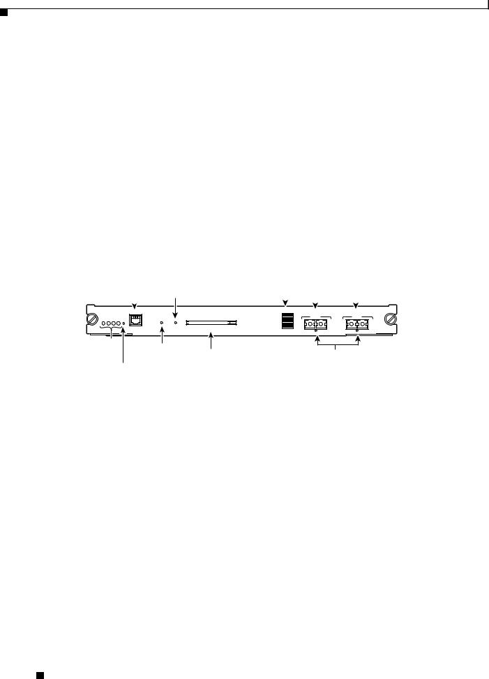
Supervisor Engine 2
Table 2-1 lists the three available versions of Supervisor Engine 2 and provides a brief description of each. Figure 2-1 shows the faceplate of Supervisor Engine 2 with the major features identified.
Table 2-1 Supervisor Engine 2 Versions
Supervisor Engine 2 Product |
Description |
Number |
|
|
|
WS-X6K-S2-PFC2 |
Supervisor Engine 2 (WS-X6K-S2-PFC2) is shipped with |
|
a factory-installed PFC2 daughter card (WS-F6K-PFC2); |
|
there is no MSFC daughter card installed. This version of |
|
Supervisor Engine 2 supports only the Catalyst operating |
|
system; it does not support Cisco IOS. Supervisor Engine 2 |
|
has two 1000BASE-X uplink ports that require the |
|
installation of GBIC transceivers. |
|
|
Catalyst 6500 Series Supervisor Engine Guide
|
OL-7397-03 |
2-1 |
|
|
|
Chapter 2 Supervisor Engines
Supervisor Engine 2
Table 2-1 |
Supervisor Engine 2 Versions (continued) |
|
|
|
|
Supervisor Engine 2 Product |
Description |
|
Number |
|
|
|
|
|
WS-X6K-S2-MSFC2 |
Supervisor Engine 2 (WS-X6K-S2-MSFC2) comes with a |
|
|
|
factory-installed PFC2 daughter card (WS-F6K-PFC2) and |
|
|
a factory-installed MSFC2 daughter card |
|
|
(WS-F6K-MSFC2). It has two 1000BASE-X uplink ports |
|
|
that require the installation of GBIC transceivers. |
|
|
|
WS-X6K-S2U-MSFC2 |
Supervisor Engine 2 (WS-X6K-S2U-MSFC2) comes with |
|
|
|
a factory-installed PFC2 daughter card (WS-F6K-PFC2) |
|
|
and a factory-installed MSFC2 daughter card |
|
|
(WS-F6K-MSFC2). Supervisor Engine 2 has two |
|
|
1000BASE-X uplink ports that require the installation of |
|
|
GBIC transceivers. The MSFC2 comes equipped with |
|
|
512 MB of memory. |
|
|
|
Figure 2-1 Supervisor Engine 2 Front Panel Features
|
|
|
Switch load |
1000BASE-X GBIC |
||||
CONSOLE port |
PCMCIA LED |
display |
|
Uplink Ports |
||||
|
|
|
|
|
|
|||
|
|
|
|
|
|
|
|
|
|
|
|
|
|
|
|
|
|
WS-X6K-SUP2-2GE |
|
|
|
Switch Load |
|
MGMT |
|
|
|
100% |
|
|
|
|
PORT 1 |
PORT 2 |
|
STATUS SYSTEMCONSOLEPWR RESET |
CONSOLE |
|
|
|
|
|
PORT |
|
|
|
|
|
MODE |
|
|
|
|
|
CONSOLE |
PCMCIA |
EJECT |
1% |
|
SUPERVISOR2 |
|
|
|
LINK |
LINK |
|
|
|
|
||
Status |
CONSOLE PORT |
|
|
|
|
LEDs |
|
|
|
||
|
MODE switch |
PCMCIA slot |
LINK LEDs |
||
RESET button
44312
Table 2-2 lists and describes Supervisor Engine 2 features
Table 2-2 |
Supervisor Engine 2 Features |
|
|
|
|
Feature |
|
Description |
|
|
|
Chassis compatibility |
Supported on all Catalyst 6500 series chassis except the Catalyst 6509-V-E |
|
|
|
chassis. |
|
|
|
Software requirements |
12.2(17d)SXB |
|
(minimum) |
|
|
|
|
|
Fan tray requirements |
All three versions of Supervisor Engine 2 are designed to operate with the |
|
|
|
low-speed fan trays; they do not require that a high-speed fan tray (either a |
|
|
fan tray 2 or Catalyst 6500-E series fan tray) be installed in the chassis. |
|
|
Low-speed fan trays provide sufficient cooling for Supervisor Engine 2. |
|
|
|
Slot installation restrictions |
Slots 1 and 2 in any Catalyst 6500 series chassis |
|
|
|
|
Backplane |
|
32-Gbps shared bus. 256 Gbps when a Switch Fabric Module |
|
|
(WS-C6500-SFM or WS-X6500-SFM2) is installed in the chassis. |
|
|
|
Hardware restrictions |
There are no additional hardware restrictions for Supervisor Engine 2. |
|
|
|
|
Catalyst 6500 Series Supervisor Engine Guide
2-2 |
OL-7397-03 |
|
|
Loading...