


 Loading...
Catalyst 3750 Switch
Hardware Installation Guide
February 2007
THE SPECIFICATIONS AND INFORMATION REGARDING THE PRODUCTS IN THIS MANUAL ARE SUBJECT TO CHANGE WITHOUT NOTICE. ALL STATEMENTS, INFORMATION, AND RECOMMENDATIONS IN THIS MANUAL ARE BELIEVED TO BE ACCURATE BUT ARE PRESENTED WITHOUT WARRANTY OF ANY KIND, EXPRESS OR IMPLIED. USERS MUST TAKE FULL RESPONSIBILITY FOR THEIR APPLICATION OF ANY PRODUCTS.
Americas Headquarters
Cisco Systems, Inc. 170 West Tasman Drive
San Jose, CA 95134-1706 USA http://www.cisco.com Tel: 408 526-4000
800 553-NETS (6387) Fax: 408 527-0883
Text Part Number: OL-6336-07
THE SOFTWARE LICENSE AND LIMITED WARRANTY FOR THE ACCOMPANYING PRODUCT ARE SET FORTH IN THE INFORMATION PACKET THAT SHIPPED WITH THE PRODUCT AND ARE INCORPORATED HEREIN BY THIS REFERENCE. IF YOU ARE UNABLE TO LOCATE THE SOFTWARE LICENSE OR LIMITED WARRANTY, CONTACT YOUR CISCO REPRESENTATIVE FOR A COPY.
The following information is for FCC compliance of Class A devices: This equipment has been tested and found to comply with the limits for a Class A digital device, pursuant to part 15 of the FCC rules. These limits are designed to provide reasonable protection against harmful interference when the equipment is operated in a commercial environment. This equipment generates, uses, and can radiate radio-frequency energy and, if not installed and used in accordance with the instruction manual, may cause harmful interference to radio communications. Operation of this equipment in a residential area is likely to cause harmful interference, in which case users will be required to correct the interference at their own expense.
The following information is for FCC compliance of Class B devices: The equipment described in this manual generates and may radiate radio-frequency energy. If it is not installed in accordance with Cisco’s installation instructions, it may cause interference with radio and television reception. This equipment has been tested and found to comply with the limits for a Class B digital device in accordance with the specifications in part 15 of the FCC rules. These specifications are designed to provide reasonable protection against such interference in a residential installation. However, there is no guarantee that interference will not occur in a particular installation.
Modifying the equipment without Cisco’s written authorization may result in the equipment no longer complying with FCC requirements for Class A or Class B digital devices. In that event, your right to use the equipment may be limited by FCC regulations, and you may be required to correct any interference to radio or television communications at your own expense.
You can determine whether your equipment is causing interference by turning it off. If the interference stops, it was probably caused by the Cisco equipment or one of its peripheral devices. If the equipment causes interference to radio or television reception, try to correct the interference by using one or more of the following measures:
•Turn the television or radio antenna until the interference stops.
•Move the equipment to one side or the other of the television or radio.
•Move the equipment farther away from the television or radio.
•Plug the equipment into an outlet that is on a different circuit from the television or radio. (That is, make certain the equipment and the television or radio are on circuits controlled by different circuit breakers or fuses.)
Modifications to this product not authorized by Cisco Systems, Inc. could void the FCC approval and negate your authority to operate the product.
The Cisco implementation of TCP header compression is an adaptation of a program developed by the University of California, Berkeley (UCB) as part of UCB’s public domain version of the UNIX operating system. All rights reserved. Copyright © 1981, Regents of the University of California.
NOTWITHSTANDING ANY OTHER WARRANTY HEREIN, ALL DOCUMENT FILES AND SOFTWARE OF THESE SUPPLIERS ARE PROVIDED “AS IS” WITH ALL FAULTS. CISCO AND THE ABOVE-NAMED SUPPLIERS DISCLAIM ALL WARRANTIES, EXPRESSED OR IMPLIED, INCLUDING, WITHOUT LIMITATION, THOSE OF MERCHANTABILITY, FITNESS FOR A PARTICULAR PURPOSE AND NONINFRINGEMENT OR ARISING FROM A COURSE OF DEALING, USAGE, OR TRADE PRACTICE.
IN NO EVENT SHALL CISCO OR ITS SUPPLIERS BE LIABLE FOR ANY INDIRECT, SPECIAL, CONSEQUENTIAL, OR INCIDENTAL DAMAGES, INCLUDING, WITHOUT LIMITATION, LOST PROFITS OR LOSS OR DAMAGE TO DATA ARISING OUT OF THE USE OR INABILITY TO USE THIS MANUAL, EVEN IF CISCO OR ITS SUPPLIERS HAVE BEEN ADVISED OF THE POSSIBILITY OF SUCH DAMAGES.
CCVP, the Cisco Logo, and the Cisco Square Bridge logo are trademarks of Cisco Systems, Inc.; Changing the Way We Work, Live, Play, and Learn is a service mark of Cisco Systems, Inc.; and Access Registrar, Aironet, BPX, Catalyst, CCDA, CCDP, CCIE, CCIP, CCNA, CCNP, CCSP, Cisco, the Cisco Certified Internetwork Expert logo, Cisco IOS, Cisco Press, Cisco Systems, Cisco Systems Capital, the Cisco Systems logo, Cisco Unity, Enterprise/Solver, EtherChannel, EtherFast, EtherSwitch, Fast Step, Follow Me Browsing, FormShare, GigaDrive, GigaStack, HomeLink, Internet Quotient, IOS, iPhone, IP/TV, iQ Expertise, the iQ logo, iQ Net Readiness Scorecard, iQuick Study, LightStream, Linksys, MeetingPlace, MGX, Networking Academy, Network Registrar, Packet, PIX, ProConnect, RateMUX, ScriptShare, SlideCast, SMARTnet, StackWise, The Fastest Way to Increase Your Internet Quotient, and TransPath are registered trademarks of Cisco Systems, Inc. and/or its affiliates in the United States and certain other countries.
All other trademarks mentioned in this document or Website are the property of their respective owners. The use of the word partner does not imply a partnership relationship between Cisco and any other company. (0612R)
Any Internet Protocol (IP) addresses used in this document are not intended to be actual addresses. Any examples, command display output, and figures included in the document are shown for illustrative purposes only. Any use of actual IP addresses in illustrative content is unintentional and coincidental.
Catalyst 3750 Switch Hardware Installation Guide
© 2004-2007 Cisco Systems, Inc. All rights reserved.

|
|
|
|
C O N T E N T S |
|
Preface vii |
|
|
|
|
Audience |
vii |
|
|
|
Purpose |
vii |
|
|
|
Organization |
vii |
|
|
|
Conventions viii |
|
||
|
Related Publications |
ix |
||
|
Obtaining Documentation, Obtaining Support, and Security Guidelines x |
|||
|
Product Overview |
|
|
|
C H A P T E R 1 |
1-1 |
|
||
|
Features |
1-1 |
|
|
|
Front Panel Description |
1-3 |
||
Fast Ethernet Front Panel Switches 1-3 |
|
Catalyst 3750-24FS Switch Front Panel Description |
1-3 |
Catalyst 3750-24TS Switch Front Panel Description |
1-4 |
Catalyst 3750-48TS Switch Front Panel Description |
1-4 |
Catalyst 3750-24PS Switch Front Panel Description |
1-5 |
Catalyst 3750-48PS Switch Front Panel Description |
1-5 |
|
Gigabit Ethernet Switch Front Panel Descriptions 1-6 |
|
|
|
|
|
|
Catalyst 3750G-12S and Catalyst 3750G-12S-SD Switches Front Panel Description |
1-6 |
|
|||
|
Catalyst 3750-24T, 3750G-24TS, and 3750G-24TS-1U Switches Front Panel Descriptions 1-6 |
|||||
|
Catalyst 3750G-48TS Switch Front Panel Description |
1-8 |
|
|
|
|
|
Catalyst 3750G-24PS Switch Front Panel Description |
1-8 |
|
|
|
|
|
Catalyst 3750G-48PS Switch Front Panel Description |
1-9 |
|
|
|
|
|
Catalyst 3750G-16TD Switch Front Panel Description |
1-9 |
|
|
|
|
|
Catalyst 3750G Integrated Wireless LAN Controller Switch Front Panel Description |
1-10 |
|
|||
|
10/100 and 10/100/1000 Ports 1-10 |
|
|
|
|
|
|
100BASE-FX Ports 1-12 |
|
|
|
|
|
|
SFP Module Slots |
1-12 |
|
|
|
|
|
SFP Modules |
1-13 |
|
|
|
|
|
XENPAK Module Slot (Catalyst 3750G-16TD Switch) 1-13 |
|
|
|
|
|
|
LEDs 1-13 |
|
|
|
|
|
|
System LED |
1-17 |
|
|
|
|
|
RPS LED 1-17 |
|
|
|
|
|
|
|
Catalyst 3750 Switch Hardware Installation Guide |
|
|
|
|
|
|
|
|
|
||
|
OL-6336-07 |
|
|
|
iii |
|
|
|
|
|
|
||

Contents
Master LED |
1-18 |
Port LEDs and Modes 1-18 |
|
Rear Panel Description |
1-22 |
Rear Panel Overview 1-22 |
|
StackWise Ports |
1-25 |
Power Connectors |
1-25 |
|
|
|
|
|
Internal Power Supply Connector |
|
1-26 |
|
|
||||
|
|
|
|
|
DC Power Connector |
1-26 |
|
|
|
|
|||
|
|
|
|
|
Cisco RPS Connector |
1-26 |
|
|
|
|
|||
|
|
|
|
|
Console Port |
1-27 |
|
|
|
|
|
|
|
|
|
|
|
|
Management Options |
1-27 |
|
|
|
|
|
|
|
|
|
|
|
|
Network Configurations |
1-28 |
|
|
|
|
|||
|
|
Switch Installation |
|
|
|
|
|
|
|
||||
C H A P T E R 2 |
|
2-1 |
|
|
|
|
|
|
|||||
|
|
|
|
|
Preparing for Installation 2-1 |
|
|
|
|
|
|||
|
|
|
|
|
Warnings |
2-2 |
|
|
|
|
|
|
|
|
|
|
|
|
Installation Guidelines |
2-5 |
|
|
|
|
|
||
|
|
|
|
|
Verifying Package Contents |
2-6 |
|
|
|
|
|||
|
|
|
|
|
Verifying Switch Operation |
2-6 |
|
|
|
|
|||
|
|
|
|
|
Powering On the Switch and Running POST 2-7 |
|
|
||||||
|
|
|
|
|
Powering Off the Switch |
2-7 |
|
|
|
|
|||
|
|
|
|
|
Planning the Stack |
2-7 |
|
|
|
|
|
|
|
|
|
|
|
|
Planning Considerations |
2-8 |
|
|
|
|
|||
|
|
|
|
|
Powering Considerations |
2-8 |
|
|
|
|
|||
|
|
|
|
|
Cabling Considerations |
2-8 |
|
|
|
|
|
||
|
|
|
|
|
Recommended Cabling Configurations |
|
2-10 |
|
|
||||
|
|
|
|
|
Installing the Switch |
2-11 |
|
|
|
|
|
|
|
|
|
|
|
|
Rack-Mounting 2-11 |
|
|
|
|
|
|
||
|
|
|
|
|
Removing Screws from the Switch |
2-12 |
|
|
|||||
|
|
|
|
|
Attaching Brackets to the Catalyst 3750G-24TS Switch |
2-14 |
|
||||||
|
|
|
|
|
Attaching Brackets to the Catalyst 3750G Integrated Wireless LAN Controller Switches 2-17 |
||||||||
|
|
|
|
|
Attaching Brackets to All Other Catalyst 3750 Switches |
2-18 |
|
||||||
|
|
|
|
|
Mounting the Switch in a Rack |
2-24 |
|
|
|||||
|
|
|
|
|
Attaching the Cable Guide 2-26 |
|
|
|
|
||||
|
|
|
|
|
Wall-Mounting 2-27 |
|
|
|
|
|
|
||
|
|
|
|
|
Attaching the Brackets to the Switch for Wall-Mounting |
2-28 |
|
||||||
|
|
|
|
|
Attaching the RPS Connector Cover |
2-28 |
|
|
|||||
|
|
|
|
|
Mounting the Switch on a Wall |
2-29 |
|
|
|||||
|
|
|
|
|
Tableor Shelf-Mounting |
2-30 |
|
|
|
|
|||
|
|
|
|
Catalyst 3750 Switch Hardware Installation Guide |
|
|
|
|
|
|
|||
|
|
|
|
|
|
|
|
|
|
||||
|
|
|
|
|
|
|
|
|
|
|
|
|
|
|
iv |
|
|
|
|
|
|
|
|
|
|
OL-6336-07 |
|
|
|
|
|
|
|
|
|
|
|
|
|
||

Contents
Connecting StackWise Cable to StackWise Ports |
2-30 |
|
Installing and Removing SFP Modules 2-33 |
|
|
Installing SFP Modules into SFP Module Slots |
2-33 |
|
Removing SFP Modules from SFP Module Slots |
2-34 |
|
Installing and Removing XENPAK Modules (Catalyst 3750G-16TD Switch) 2-35 |
||
Installing a XENPAK Module |
2-36 |
|
Removing a XENPAK Module |
2-38 |
|
|
Connecting to the 10/100 and 10/100/1000 Ports |
2-39 |
||||||
|
Connecting to an SFP Module |
2-41 |
|
|
|
|||
|
Connecting to a Fiber-Optic SFP Module |
2-41 |
|
|||||
|
Connecting to 1000BASE-T SFP Modules |
2-43 |
|
|||||
|
Connecting to a XENPAK Module |
2-44 |
|
|
|
|||
|
Where to Go Next |
2-45 |
|
|
|
|
|
|
|
Troubleshooting 3-1 |
|
|
|
|
|
|
|
C H A P T E R 3 |
|
|
|
|
|
|
|
|
|
Diagnosing Problems |
3-1 |
|
|
|
|
|
|
|
Verify Switch POST Results |
|
3-2 |
|
|
|
||
|
Monitor Switch LEDs |
3-2 |
|
|
|
|
|
|
|
Verify Switch Connections |
3-2 |
|
|
|
|||
|
Bad or Damaged Cable |
|
3-2 |
|
|
|
||
|
Ethernet and Fiber Cables |
3-2 |
|
|
|
|||
|
Link Status |
3-3 |
|
|
|
|
|
|
|
PoE Connections |
3-3 |
|
|
|
|
|
|
|
Transceiver Module Port Issues |
3-3 |
|
|
||||
|
Port and Interface Settings 3-4 |
|
|
|
||||
|
Ping the End Device |
3-4 |
|
|
|
|
||
|
Spanning Tree Loops |
3-4 |
|
|
|
|||
|
Monitor Switch Performance |
3-5 |
|
|
|
|||
|
Speed, Duplex, and Autonegotiation |
3-5 |
|
|||||
|
Autonegotiation and NIC Cards |
3-5 |
|
|
||||
|
Cabling Distance |
3-5 |
|
|
|
|
|
|
|
Clearing the Switch IP Address and Configuration |
3-6 |
||||||
|
Replacing a Failed Stack Member |
3-6 |
|
|
|
|||
|
Finding the Switch Serial Number |
3-7 |
|
|
|
|||
Catalyst 3750 Switch Hardware Installation Guide
|
OL-6336-07 |
v |
|

Contents
A P P E N D I X A |
Technical Specifications |
A-1 |
|
|
|
|
|
|
|||
|
|
Connector and Cable Specifications |
|
|
|
|
|
||||
A P P E N D I X |
B |
|
B-1 |
|
|
|
|||||
|
|
Connector Specifications |
B-1 |
|
|
|
|
|
|
||
|
|
10/100 and 10/100 /1000 Ports |
|
B-2 |
|
|
|
||||
|
|
100BASE-FX Ports |
B-2 |
|
|
|
|
|
|
|
|
|
|
SFP Module Ports |
B-3 |
|
|
|
|
|
|
|
|
|
|
XENPAK Module Ports (Catalyst 3750G-16TD Switch) |
B-4 |
||||||||
|
|
Console Port |
B-5 |
|
|
|
|
|
|
|
|
|
|
Cable and Adapter Specifications |
B-5 |
|
|
|
|||||
|
|
SFP Module Cable Specifications |
B-5 |
|
|
||||||
|
|
Two Twisted-Pair Cable Pinouts |
|
B-6 |
|
|
|||||
|
|
Four Twisted-Pair Cable Pinouts for 10/100 Ports B-7 |
|
||||||||
|
|
Identifying a Crossover Cable |
B-8 |
|
|
|
|||||
|
|
Four Twisted-Pair Cable Pinouts for 1000BASE-T Ports |
B-8 |
||||||||
|
|
Crossover Cable and Adapter Pinouts |
B-9 |
|
|
||||||
|
|
Identifying a Crossover Cable |
B-9 |
|
|
||||||
|
|
Adapter Pinouts |
B-10 |
|
|
|
|
|
|
||
|
|
Connecting to DC Power |
|
|
|
|
|
|
|
|
|
A P P E N D I X |
C |
C-1 |
|
|
|
|
|
|
|
||
|
|
Connecting to DC Power |
C-1 |
|
|
|
|
|
|
||
|
|
Preparing for Installation |
C-2 |
|
|
|
|
|
|||
|
|
Grounding the Switch |
C-2 |
|
|
|
|
|
|
||
|
|
Wiring the DC-Input Power Source |
C-4 |
|
|
||||||
|
|
Configuring the Switch with the CLI-Based Setup Program |
|
||||||||
A P P E N D I X |
D |
D-1 |
|||||||||
|
|
Accessing the CLI |
D-2 |
|
|
|
|
|
|
|
|
|
|
Accessing the CLI Through Express Setup |
D-2 |
|
|||||||
|
|
Accessing the CLI Through the Console Port |
D-2 |
|
|||||||
|
|
Taking Out What You Need |
D-3 |
|
|
|
|
|
|||
|
|
Stacking the Switches (Optional) |
D-4 |
|
|
|
|
||||
|
|
Connecting to the Console Port |
D-5 |
|
|
|
|
||||
|
|
Starting the Terminal Emulation Software |
D-6 |
|
|
||||||
|
|
Connecting to a Power Source |
D-6 |
|
|
|
|
|
|||
|
|
Entering the Initial Configuration Information D-7 |
|
||||||||
|
|
IP Settings |
D-7 |
|
|
|
|
|
|
|
|
|
|
Completing the Setup Program |
D-7 |
|
|
|
|||||
I N D E X
|
Catalyst 3750 Switch Hardware Installation Guide |
vi |
OL-6336-07 |

Preface
Audience
This guide is for the networking or computer technician responsible for installing the Catalyst 3750 switches. We assume that you are familiar with the concepts and terminology of Ethernet and local area networking.
Purpose
This guide documents the hardware features of the Catalyst 3750 family of switches. It describes the physical and performance characteristics of each switch, explains how to install a switch, and provides troubleshooting information.
This guide does not describe system messages that you might receive or how to configure your switch. For more information, see the switch software configuration guide, the switch command reference, and the switch system message guide on the Cisco.com Product Documentation home page. For information about the standard Cisco IOS Release 12.1 or 12.2 commands, see the Cisco IOS documentation set from the Cisco.com home page by choosing Support > Documentation > Product and Support Documentation/Cisco IOS Software.
Organization
This guide is organized into these chapters:
Chapter 1, “Product Overview,” is a physical and functional overview of the Catalyst 3750 family of switches. It describes the switch ports, the standards they support, and the switch LEDs.
Chapter 2, “Switch Installation,” contains the procedures on how to power on the switch; stack the switches; install the switch in a rack, on a wall, on a table, or shelf; and how to make port connections.
Chapter 3, “Troubleshooting,” describes how to identify and resolve some of the problems that might occur when you install the switch and how to identify the serial number when it is necessary to call technical support for help.
Appendix A, “Technical Specifications,” lists the physical and environmental specifications for the switches and the regulatory agency approvals.
Appendix B, “Connector and Cable Specifications,” describes the connectors, cables, and adapters that you use to connect the switch.
Catalyst 3750 Switch Hardware Installation Guide
|
OL-6336-07 |
vii |
|
Preface
Conventions
Appendix C, “Connecting to DC Power,” describes how to make DC power connections to the Catalyst 3750G-12S-SD switch.
Appendix D, “Configuring the Switch with the CLI-Based Setup Program,” provides a command-line interface (CLI)-based setup procedure for a standalone switch or a switch stack.
Conventions
This document uses these conventions and symbols for notes, cautions, and warnings:
Note Means reader take note. Notes contain helpful suggestions or references to materials not contained in this manual.
Caution Means reader be careful. In this situation, you might do something that could result in equipment damage or loss of data.
Warning IMPORTANT SAFETY INSTRUCTIONS
This warning symbol means danger. You are in a situation that could cause bodily injury. Before you work on any equipment, be aware of the hazards involved with electrical circuitry and be familiar with standard practices for preventing accidents. Use the statement number provided at the end of each warning to locate its translation in the translated safety warnings that accompanied this device. Statement 1071
SAVE THESE INSTRUCTIONS
The safety warnings for this product are translated into several languages in the Regulatory Compliance and Safety Information for the Catalyst 3750 Switch that ships with the product. The EMC regulatory statements are also included in that guide.
Catalyst 3750 Switch Hardware Installation Guide
|
viii |
OL-6336-07 |
|
|
|

Preface
Related Publications
Related Publications
You can order printed copies of documents with a DOC-xxxxxx= number from the Cisco.com sites and from the telephone numbers listed in the URL referenced in the “Obtaining Documentation, Obtaining Support, and Security Guidelines” section on page x.
These documents provide complete information about the switch and are available from this
Cisco.com site:
http://www.cisco.com/en/US/products/hw/switches/ps5023/tsd_products_support_series_home.html
•Catalyst 3750 Switch Getting Started Guide (order number DOC-7816663=)
•Catalyst 3750G Integrated Wireless LAN Controller Getting Started Guide (order number DOC-7817540=)
•Regulatory Compliance and Safety Information for the Catalyst 3750 Switch
(order number DOC-7816664=)
•Release Notes for the Catalyst 3750 Switch (not orderable but available on Cisco.com)
•Release Notes for the Catalyst 3750G Integrated Wireless LAN Controller Switch (not orderable but available on Cisco.com)
Note Before installing, configuring, or upgrading the switch, see the release notes on Cisco.com for the latest information.
•Catalyst 3750 Switch Software Configuration Guide (not orderable but available on Cisco.com)
•Catalyst 3750 Switch Command Reference (not orderable but available on Cisco.com)
•Catalyst 3750, 3560, 3550, 2970, and 2960 Switch System Message Guide (not orderable but available on Cisco.com)
•Device manager online help (available on the switch)
•Getting Started with Cisco Network Assistant (not orderable but available on Cisco.com)
•Cisco Small Form-Factor Pluggable Modules Installation Notes (order number DOC-7815160=) These compatibility matrix documents are available from this Cisco.com site: http://www.cisco.com/en/US/products/hw/modules/ps5455/products_device_support_tables_list.html
•Cisco Gigabit Ethernet Transceiver Modules Compatibility Matrix (not orderable but available on Cisco.com)
•Cisco 100-Megabit Ethernet SFP Modules Compatibility Matrix (not orderable but available on Cisco.com)
•Cisco CWDM SFP Transceiver Compatibility Matrix (not orderable but available on Cisco.com)
•Cisco Small Form-Factor Pluggable Modules Compatibility Matrix (not orderable but available on Cisco.com)
•Compatibility Matrix for 1000BASE-T Small Form-Factor Pluggable Modules (not orderable but available on Cisco.com)
Catalyst 3750 Switch Hardware Installation Guide
|
OL-6336-07 |
ix |
|

Preface
Obtaining Documentation, Obtaining Support, and Security Guidelines
Obtaining Documentation, Obtaining Support, and Security
Guidelines
For information on obtaining documentation, obtaining support, providing documentation feedback, security guidelines, and also recommended aliases and general Cisco documents, see the monthly What's New in Cisco Product Documentation, which also lists all new and revised Cisco technical documentation, at this URL:
http://www.cisco.com/en/US/docs/general/whatsnew/whatsnew.html
Catalyst 3750 Switch Hardware Installation Guide
|
x |
OL-6336-07 |
|
|
|
C H A P T E R 1
Product Overview
The Catalyst 3750 family of switches—also referred to as the switches—are stackable Ethernet switches to which you can connect devices like Cisco IP Phones, Cisco Wireless Access Points workstations, and other network devices such as servers, routers, and other switches. This chapter provides a functional overview of the Catalyst 3750 switch models. These topics are included:
•Features, page 1-1
•Front Panel Description, page 1-3
•Rear Panel Description, page 1-22
•Management Options, page 1-27
Features
The switches can be deployed as backbone switches, aggregating 10BASE-T, 100BASE-TX, and 1000BASE-T Ethernet traffic from other network devices. See the switch software configuration guide for examples that show how you might deploy the switches in your network.
Figure 1-2 through Figure 1-13 show the Catalyst 3750 switches.
These are the switch features:
•Fast Ethernet Configurations
–Catalyst 3750-24FS switch—24 100BASE-FX ports and 2 small form-factor pluggable (SFP) module slots
–Catalyst 3750-24TS switch—24 10/100 Ethernet ports and 2 SFP module slots
–Catalyst 3750-48TS switch—48 10/100 Ethernet ports and 4 SFP module slots
–Catalyst 3750-24PS switch—24 10/100 Power over Ethernet (PoE) ports and 2 SFP module slots
–Catalyst 3750-48PS switch—48 10/100 PoE ports and 4 SFP module slots
•Gigabit Ethernet Configurations
–Catalyst 3750G-12S switch—12 SFP module slots
–Catalyst 3750G-12S-SD switch—12 SFP module slots
–Catalyst 3750G-24T switch—24 10/100/1000 Ethernet ports
–Catalyst 3750G-24TS switch—1.5 rack units (RU)—24 10/100/1000 Ethernet ports and 4 SFP module slots
Catalyst 3750 Switch Hardware Installation Guide
|
OL-6336-07 |
1-1 |
|
|
|
Chapter 1 Product Overview
Features
–Catalyst 3750G-24TS-1U switch—1 RU—24 10/100/1000 Ethernet ports and 4 SFP module slots
–Catalyst 3750G-48TS switch—48 10/100/1000 Ethernet ports and 4 SFP module slots
–Catalyst 3750G-24PS switch—24 10/100/1000 PoE ports and 4 SFP module slots
–Catalyst 3750G-48PS switch—48 10/100/1000 PoE ports and 4 SFP module slots
–Catalyst 3750G-24WS-S25 switch—24 10/100/1000 PoE ports, 2 SFP module slots, and an integrated Cisco wireless LAN controller supporting up to 25 Cisco Lightweight Access Points
–Catalyst 3750G-24WS-S50 switch—24 10/100/1000 PoE ports, 2 SFP module slots, and an integrated Cisco wireless LAN controller supporting up to 50 Cisco Lightweight Access Points
•10-Gigabit Ethernet Configuration
–Catalyst 3750G-16TD switch—16 10/100/1000 Ethernet ports and 1 10-Gigabit Ethernet XENPAK module slot
Note The 10-Gigabit Ethernet XENPAK modules are referred to as 10-Gigabit Ethernet module ports in the software documentation.
•The switches support these SFP modules:
–100BASE-FX multimode fiber (MMF)
–1000BASE-BX
–1000BASE-LX
–1000BASE-SX
–1000BASE-ZX
–1000BASE-T
–Coarse wavelength-division multiplexing (CWDM)
Note When you install 1000BASE-T SFP modules in Catalyst 3750 switches, they can operate either at 10, 100, or 1000 Mb/s in full-duplex mode or at 10 or 100 Mb/s in half-duplex mode.
•For a list of the XENPAK modules that the Catalyst 3750G-16TD switch supports, see Table B-2 on page B-4.
•Configuration
–For 10/100 ports, autonegotiates the speed and duplex settings
–For 10/100/1000 ports, autonegotiates the speed and supports only full-duplex mode
Note You can configure duplex mode to half, full, or autonegotiate on Gigabit Ethernet interfaces if the speed is set to 10 or 100 Mb/s. You cannot configure half-duplex mode on Gigabit Ethernet interfaces if the interface speed is 1000 Mb/s.
•The Catalyst 3750 switches support stacking. You can stack up to nine switches in a stack by cabling the StackWise ports. StackWise ports are not user-configurable.
Catalyst 3750 Switch Hardware Installation Guide
1-2 |
OL-6336-07 |
|
|
Chapter 1 Product Overview
Front Panel Description
•Switches are hot-swappable.
•Connection for an optional Cisco RPS 2300 or Cisco RPS 675 redundant power system (RPS) that operates on AC input and supplies backup DC power output to the Catalyst 3750 switches. The Catalyst 3750G-12S-SD switch does not support an RPS.
Front Panel Description
These sections describe the Fast Ethernet and Gigabit Ethernet switches:
•Fast Ethernet Front Panel Switches, page 1-3
•Gigabit Ethernet Switch Front Panel Descriptions, page 1-6
•10/100 and 10/100/1000 Ports, page 1-10
•SFP Module Slots, page 1-12
•XENPAK Module Slot (Catalyst 3750G-16TD Switch), page 1-13
•LEDs, page 1-13
Fast Ethernet Front Panel Switches
These sections describe the front panels for the Catalyst 3750 Fast Ethernet switches:
•Catalyst 3750-24FS Switch Front Panel Description, page 1-3
•Catalyst 3750-24TS Switch Front Panel Description, page 1-4
•Catalyst 3750-48TS Switch Front Panel Description, page 1-4
•Catalyst 3750-24PS Switch Front Panel Description, page 1-5
•Catalyst 3750-48PS Switch Front Panel Description, page 1-5
Catalyst 3750-24FS Switch Front Panel Description
The 100BASE-FX ports on the Catalyst 3750-24FS switch are numbered 1 through 24, as shown in Figure 1-1. The SFP modules slots are numbered 1 (left) and 2 (right).
Figure 1-1 Catalyst 3750-24FS Front Panel
SYST |
|
|
RPS |
1 |
|
MASTR |
|
|
STAT |
2 |
|
3 |
|
|
DUPLX |
4 |
|
5 |
|
|
SPEED |
6 |
|
STACK |
7 |
|
8 |
|
|
MODE |
|
9 |
10 |
11 |
|
|
|
|
|
|
|
|
|
|
|
|
|
|
|
|
12 |
13 |
|
|
|
|
|
|
|
|
|
|
|
|
|
|
|
|
14 |
15 |
|
|
|
|
|
|
|
|
|
|
|
|
|
|
|
|
16 |
17 |
|
|
|
|
|
|
|
|
|
|
|
|
|
|
|
18 |
19 |
|
|
|
|
Catalyst |
3560 |
|
|
|
|
|
|
|
|
|
|
20 |
21 |
|
|
|
SERIES |
|
|
|
|
|
|
|
|
|
|
|
22 |
|
|
|
|
|
|
|
|
|
|
|
|
|
|
|
|
|
23 |
24 |
|
|
|
|
|
|
|
|
|
|
|
|
|
|
|
1 |
|
|
2
1
2
132240
1 |
10/100 ports |
2 |
SFP module slots |
|
|
|
|
Catalyst 3750 Switch Hardware Installation Guide
|
OL-6336-07 |
1-3 |
|
|
|
Chapter 1 Product Overview
Front Panel Description
Catalyst 3750-24TS Switch Front Panel Description
The 10/100 ports on the Catalyst 3750-24TS switch are numbered 1 through 24. The ports are grouped in pairs. The first member of the pair (port 1) is above the second member (port 2), as shown in
Figure 1-2. Port 3 is above port 4, and so on. The SFP module slots are numbered 1 (left) and 2 (right).
Figure 1-2 Catalyst 3750-24TS Front Panel
SYST |
|
|
|
|
|
|
|
|
|
|
|
|
|
|
|
|
|
|
|
|
|
RPS |
|
|
|
|
|
|
|
|
|
|
|
|
|
|
|
|
|
|
|
|
|
MASTR |
|
|
|
|
|
|
|
|
|
|
|
|
|
|
|
|
|
|
|
|
|
STAT |
|
|
|
|
|
|
|
|
|
|
|
|
|
|
|
|
|
|
|
|
|
DUPLX |
1 |
|
|
|
|
|
|
|
|
|
|
|
|
|
|
|
|
|
|
|
|
SPEED |
2 |
4 |
|
|
|
|
|
|
|
|
|
|
|
|
|
|
|
|
|
|
|
|
3 |
|
|
|
|
|
|
|
|
|
|
|
|
|
|
|
|
|
|
||
STACK |
1X |
|
5 |
6 |
8 |
|
|
|
|
|
|
|
|
|
|
|
|
|
|
|
|
MODE |
|
|
|
7 |
10 |
|
|
|
|
|
|
|
|
|
|
|
|
|
|
|
|
|
|
|
|
9 |
11 |
12 |
|
|
|
|
|
|
|
|
|
|
|
|
|
||
|
|
|
|
|
|
|
|
11X |
13 |
14 |
15 |
16 |
|
|
|
|
|
|
|
|
|
|
|
|
|
|
|
|
|
13X |
|
|
17 |
18 |
|
|
|
|
|
|
|
||
|
|
|
|
|
|
|
|
|
|
|
|
19 |
20 |
|
|
|
|
|
|||
|
2X |
|
|
|
|
|
|
|
|
|
|
|
|
|
|
|
21 |
22 |
23 |
24 |
Catalyst |
|
|
|
|
|
|
|
|
|
|
|
|
|
|
|
|
|
|
|
|||
|
|
|
|
|
|
|
|
|
|
|
|
|
|
|
|
|
|
|
|
|
3750 SERIES |
|
|
|
|
|
|
|
|
|
|
|
|
|
|
|
|
|
|
|
|
23X |
|
|
|
|
|
|
|
|
|
12X |
|
|
|
|
|
|
|
|
|
|
|
|
|
|
|
|
|
|
|
|
|
14X |
|
|
|
|
|
|
|
|
|
|
|
|
|
|
|
|
|
|
|
|
|
|
|
|
|
|
|
|
|
|
|
|
|
24X |
1 |
|
|
|
|
|
|
|
|
|
|
|
|
|
|
|
|
|
|
|
|
2 |
86541
1
2
1 |
10/100 ports |
2 |
SFP module slots |
|
|
|
|
Catalyst 3750-48TS Switch Front Panel Description
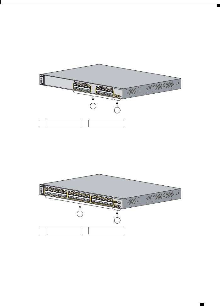
The 10/100 ports on the Catalyst 3750-48TS switch are numbered 1 through 48. The ports are grouped in pairs. The first member of the pair (port 1) is above the second member (port 2), as shown in Figure 1-3. Port 3 is above port 4, and so on. The SFP module slots are numbered 1 to 4.
Figure 1-3 Catalyst 3750-48TS Front Panel
|
|
1 |
2 |
4 |
|
|
|
|
|
|
|
|
|
|
|
|
|
|
|
|
|
|
|
|
|
|
|
|
|
|
|
|
|
|
|
|
|
|
|
|
|
|
|
|
|
|
|
|
|
3 |
6 |
|
|
|
|
|
|
|
|
|
|
|
|
|
|
|
|
|
|
|
|
|
|
|
|
|
|
|
|
|
|
|
|
|
|
|
|
|
|
|
|
|
|
|
|
|
|
5 |
8 |
|
|
|
|
|
|
|
|
|
|
|
|
|
|
|
|
|
|
|
|
|
|
|
|
|
|
|
|
|
|
|
|
|
|
|
|
|
|
|
|
|
|
SYST |
1X |
|
|
7 |
10 |
|
|
|
|
|
|
|
|
|
|
|
|
|
|
|
|
|
|
|
|
|
|
|
|
|
|
|
|
|
|
|
|
|
|
|
|
|
|
|
|
|
|
|
|
|
9 |
11 |
12 |
|
|
|
|
|
|
|
|
|
|
|
|
|
|
|
|
|
|
|
|
|
|
|
|
|
|
|
|
|
|
|
|
|
|
|
|
|
||
|
RPS |
|
|
|
|
|
|
13 |
14 |
|
|
|
|
|
|
|
|
|
|
|
|
|
|
|
|
|
|
|
|
|
|
|
|
|
|
|
|
|
|
|
|
|
|
|
||
|
MASTR |
|
|
|
|
|
|
|
|
15 |
16 |
|
|
|
|
|
|
|
|
|
|
|
|
|
|
|
|
|
|
|
|
|
|
|
|
|
|
|
|
|
|
|
|
|
||
|
STAT |
|
|
|
|
|
|
|
|
|
|
|
|
17 |
18 |
19 |
20 |
|
|
|
|
|
|
|
|
|
|
|
|
|
|
|
|
|
|
|
|
|
|
|
|
|
|
|
|
|
|
DUPLX |
|
|
|
|
|
|
|
|
|
|
|
|
|
|
21 |
22 |
|
|
|
|
|
|
|
|
|
|
|
|
|
|
|
|
|
|
|
|
|
|
|
|
|
|
|
||
|
SPEED |
|
|
|
|
|
|
|
|
|
|
|
15X 17X |
|
|
|
23 |
24 |
|
|
|
|
|
|
|
|
|
|
|
|
|
|
|
|
|
|
|
|
|
|
|
|
|
|||
|
STACK |
|
|
|
|
|
|
|
|
|
|
|
|
|
|
|
|
|
|
|
|
25 |
26 |
27 |
28 |
|
|
|
|
|
|
|
|
|
|
|
|
|
|
|
|
|
|
|
|
|
MODE |
2X |
|
|
|
|
|
|
|
|
|
|
|
|
|
|
|
|
|
|
|
|
|
29 |
30 |
|
|
|
|
|
|
|
|
|
|
|
|
|
|
|
|
|
|
|
|||
|
|
|
|
|
|
|
|
|
|
|
|
|
|
|
|
|
|
|
|
|
|
|
|
31 |
32 |
|
|
|
|
|
|
|
|
|
|
|
|
|
|
|
|
|
||||
|
|
|
|
|
|
|
|
|
|
|
|
|
|
|
|
|
|
|
|
|
|
|
|
|
|
|
|
|
|
|
|
|
|
|
|
|
|
|
|
|
|
|
|
|
||
|
|
|
|
|
|
|
|
|
|
|
|
|
|
|
|
|
|
|
|
|
|
|
|
|
|
|
|
|
33 |
34 |
35 |
36 |
|
|
|
|
|
|
|
|
|
|
|
|
|
|
|
|
|
|
|
|
|
|
|
|
|
|
|
|
|
|
|
|
|
|
|
|
|
|
|
|
|
|
|
31X 33X |
|
|
|
37 |
38 |
39 |
40 |
|
|
|
|
|
|
|
|
|
|
|
|
|
|
|
|
|
|
|
|
|
|
|
|
|
|
|
|
|
|
|
|
|
|
|
|
|
|
|
|
|
|
|
|
41 |
42 |
|
|
|
|
|
|
|
|
|||
|
|
|
|
|
|
|
|
|
|
|
|
|
16X |
18X |
|
|
|
|
|
|
|
|
|
|
|
|
|
|
|
|
|
|
|
|
|
|
|
|
43 |
44 |
45 |
46 |
|
|
|
|
|
|
|
|
|
|
|
|
|
|
|
|
|
|
|
|
|
|
|
|
|
|
|
|
|
|
|
|
|
|
|
|
|
|
|
|
|
|
|
|
47 |
48 |
Catalyst |
3750 SERIES |
|||
|
|
|
|
|
|
|
|
|
|
|
|
|
|
|
|
|
|
|
|
|
|
|
|
|
|
|
|
|
|
|
|
|
|
|
|
|
|
|
|
|
|
|
|
|
|
|
|
|
|
|
|
|
|
|
|
|
|
|
|
|
|
|
|
|
|
|
|
|
|
|
|
|
|
|
|
|
|
|
|
|
|
|
|
|
|
|
|
|
|
|
47X |
|
|
|
|
|
|
|
|
|
|
|
|
|
|
|
|
|
|
|
|
|
|
|
|
|
|
|
|
|
|
|
32X 34X |
|
|
|
|
|
|
|
|
|
|
|
|
|
|
|
1 |
|
|
|
|
|
|
|
|
|
|
|
|
|
|
|
|
|
|
|
|
|
|
|
|
|
|
|
|
|
|
|
|
|
|
|
|
|
|
|
|
|
|
|
|
|
|
3 |
|
|
|
|
|
|
|
|
|
|
|
|
|
|
|
|
|
|
|
|
|
|
|
|
|
|
|
|
|
|
|
|
|
|
|
|
|
|
|
|
|
|
|
|
|
|
|
|
|
|
|
|
|
|
|
|
|
|
|
|
|
|
|
|
|
|
|
|
|
|
|
|
|
|
|
|
|
|
|
|
|
|
|
|
|
|
|
|
|
|
|
|
48X |
2 |
4 |
|
|
|
|
|
|
|
|
|
|
|
|
|
|
|
|
|
|
|
|
|
|
|
|
|
|
|
|
|
|
|
|
|
|
|
|
|
|
|
|
|
|
|
|
|
||
1
2
86542
1 |
10/100 ports |
2 |
SFP module slots |
|
|
|
|
Catalyst 3750 Switch Hardware Installation Guide
1-4 |
OL-6336-07 |
|
|
Chapter 1 Product Overview
Front Panel Description
Catalyst 3750-24PS Switch Front Panel Description
The 10/100 PoE ports on the Catalyst 3750-24PS switch are grouped in pairs. The first member of the pair (port 1) is above the second member (port 2), as shown in Figure 1-4. Port 3 is above port 4, and so on. The SFP module slots are numbered 1 and 2.
Figure 1-4 Catalyst 3750-24PS Switch Front Panel
SYST |
|
|
|
|
|
|
|
|
|
|
|
|
|
|
|
|
|
|
|
|
|
|
|
|
|
RPS |
|
|
|
|
|
|
|
|
|
|
|
|
|
|
|
|
|
|
|
|
|
|
|
|
|
STAT |
|
|
|
|
|
|
|
|
|
|
|
|
|
|
|
|
|
|
|
|
|
|
|
|
|
DUPLX |
|
|
|
|
|
|
|
|
|
|
|
|
|
|
|
|
|
|
|
|
|
|
|
|
|
SPEED |
|
1 |
2 |
3 |
4 |
|
|
|
|
|
|
|
|
|
|
|
|
|
|
|
|
|
|
|
|
PoE |
1X |
|
|
|
5 |
6 |
8 |
|
|
|
|
|
|
|
|
|
|
|
|
|
|
|
|
|
|
MODE |
|
|
|
|
|
7 |
10 |
|
|
|
|
|
|
|
|
|
|
|
|
|
|
|
|
|
|
|
|
|
|
|
|
|
9 |
11 |
12 |
|
|
|
|
|
|
|
|
|
|
|
|
|
|
|
|
|
|
|
|
|
|
|
|
|
|
11X |
13 |
14 |
15 |
16 |
|
|
|
|
|
|
|
|
|
|
|
|
|
|
|
|
|
|
|
|
|
13X |
|
17 |
18 |
|
|
|
|
|
|
|
|
|
|||
|
|
|
|
|
|
|
|
|
|
|
|
|
|
19 |
20 |
|
|
|
|
Catalyst |
|
|
|||
|
2X |
|
|
|
|
|
|
|
|
|
|
|
|
|
|
|
|
|
21 |
22 |
23 |
24 |
3750 |
SERIES |
|
|
|
|
|
|
|
|
|
|
|
|
|
|
|
|
|
|
|
|
|
|
|
23X |
|
|
|
|
|
|
|
|
|
|
|
|
|
12X |
|
|
|
|
|
|
|
|
|
|
|
|
|
|
|
|
|
|
|
|
|
|
|
|
|
|
14X |
|
|
|
|
|
|
|
|
|
|
|
|
|
|
|
|
|
|
|
|
|
|
|
|
|
|
|
|
|
|
|
|
|
|
|
|
24X |
1 |
|
2 |
|
|
|
|
|
|
|
|
|
|
|
|
|
|
|
|
|
|
|
|
|
|
|
|
1
2
104577
1 10/100 PoE ports 2 SFP module slots
Catalyst 3750-48PS Switch Front Panel Description
The 10/100 PoE ports on the Catalyst 3750-48PS switch are grouped in pairs. The first member of the pair (port 1) is above the second member (port 2), as shown in Figure 1-5. Port 3 is above port 4, and so on. The SFP module slots are numbered 1 to 4.
Figure 1-5 Catalyst 3750-48PS Switch Front Panel
|
|
1 |
2 |
3 |
4 |
|
|
|
|
|
|
|
|
|
|
|
|
|
|
|
|
|
|
|
|
|
|
|
|
|
|
|
|
|
|
|
|
|
|
|
|
|
|
|
|
|
|
|
|
|
|
|
SYST |
1X |
|
|
|
5 |
6 |
7 |
8 |
|
|
|
|
|
|
|
|
|
|
|
|
|
|
|
|
|
|
|
|
|
|
|
|
|
|
|
|
|
|
|
|
|
|
|
|
|
|
|
|
|
|
|
RPS |
|
|
|
|
|
|
|
|
9 |
10 |
11 |
12 |
13 |
|
|
|
|
|
|
|
|
|
|
|
|
|
|
|
|
|
|
|
|
|
|
|
|
|
|
|
|
|
|
|
|
|
|
|
|
|
|
STAT |
|
|
|
|
|
|
|
|
|
|
|
|
14 |
15 |
16 |
|
|
|
|
|
|
|
|
|
|
|
|
|
|
|
|
|
|
|
|
|
|
|
|
|
|
|
|
|
|
|
|
|
|
|
|
|
|
|
|
|
|
|
|
|
|
|
|
|
|
17 |
|
|
|
|
|
|
|
|
|
|
|
|
|
|
|
|
|
|
|
|
|
|
|
|
|
|
|
|
|
|
|
|
|
|||
|
DUPLX |
|
|
|
|
|
|
|
|
|
|
|
|
|
|
|
|
|
18 |
19 |
20 |
21 |
|
|
|
|
|
|
|
|
|
|
|
|
|
|
|
|
|
|
|
|
|
|
|
|
|
|
|
|
|
|
SPEED |
|
|
|
|
|
|
|
|
|
|
|
|
|
|
|
15X |
17X |
|
|
22 |
23 |
|
|
|
|
|
|
|
|
|
|
|
|
|
|
|
|
|
|
|
|
|
|
|
|
|
|
|
||
MODE |
PoE |
2X |
|
|
|
|
|
|
|
|
|
|
|
|
|
|
|
|
|
|
|
|
|
|
24 |
25 |
26 |
27 |
28 |
29 |
|
|
|
|
|
|
|
|
|
|
|
|
|
|
|
|
|
|
|
|
|
|
|
|
|
|
|
|
|
|
|
|
|
|
|
|
|
|
|
|
|
|
|
|
|
|
|
30 |
31 |
|
|
|
|
|
|
|
|
|
|
|
|
|
|
|
|
|
|
|
|||||
|
|
|
|
|
|
|
|
|
|
|
|
|
|
|
|
|
|
|
|
|
|
|
|
|
|
|
|
|
|
|
|
32 |
|
|
|
|
|
|
|
|
|
|
|
|
|
|
|
|
|
|
|
|
|
|
|
|
|
|
|
|
|
|
|
|
|
|
|
|
|
|
|
|
|
|
|
|
|
|
|
|
|
|
|
|
33 |
34 |
35 |
36 |
37 |
|
|
|
|
|
|
|
|
|
|
|
|
|
|
|
|
|
|
|
|
|
|
|
|
|
|
|
|
|
|
|
|
|
|
|
|
|
|
|
|
|
|
|
|
|
|
|
31X 33X |
|
38 |
39 |
|
|
|
|
|
|
|
|
|
|
|
|
|||
|
|
|
|
|
|
|
|
|
|
|
|
|
|
|
|
|
|
|
|
|
|
|
|
|
|
|
|
|
|
|
|
|
|
|
|
40 |
41 |
|
|
|
|
|
|
|
|
|
|
||||
|
|
|
|
|
|
|
|
|
|
|
|
|
|
|
|
|
16X |
18X |
|
|
|
|
|
|
|
|
|
|
|
|
|
|
|
|
|
|
|
|
|
|
|
42 |
43 |
44 |
45 |
|
|
|
Catalyst |
3750 |
|
|
|
|
|
|
|
|
|
|
|
|
|
|
|
|
|
|
|
|
|
|
|
|
|
|
|
|
|
|
|
|
|
|
|
|
|
|
|
|
|
|
|
|
|
|
|
46 |
47 |
48 |
SERIES |
||
|
|
|
|
|
|
|
|
|
|
|
|
|
|
|
|
|
|
|
|
|
|
|
|
|
|
|
|
|
|
|
|
|
|
|
|
|
|
|
|
|
|
|
|
|
|
|
|
47X |
|
|
|
|
|
|
|
|
|
|
|
|
|
|
|
|
|
|
|
|
|
|
|
|
|
|
|
|
|
|
|
|
|
|
|
|
32X 34X |
|
|
|
|
|
|
|
|
|
|
|
|
|
|
|
|
1 |
|
|
|
|
|
|
|
|
|
|
|
|
|
|
|
|
|
|
|
|
|
|
|
|
|
|
|
|
|
|
|
|
|
|
|
|
|
|
|
|
|
|
|
|
|
|
|
|
|
|
|
3 |
|
|
|
|
|
|
|
|
|
|
|
|
|
|
|
|
|
|
|
|
|
|
|
|
|
|
|
|
|
|
|
|
|
|
|
|
|
|
|
|
|
|
|
|
|
|
|
|
|
|
|
|
|
|
|
|
|
|
|
|
|
|
|
|
|
|
|
|
|
|
|
|
|
|
|
|
|
|
|
|
|
|
|
|
|
|
|
|
|
|
|
|
|
|
|
|
|
|
|
|
|
48X |
|
2 |
4 |
|
|
|
|
|
|
|
|
|
|
|
|
|
|
|
|
|
|
|
|
|
|
|
|
|
|
|
|
|
|
|
|
|
|
|
|
|
|
|
|
|
|
|
|
|
|
|
|
|
|
|
1
2
104576
1 10/100 PoE ports 2 SFP module slots
Catalyst 3750 Switch Hardware Installation Guide
|
OL-6336-07 |
1-5 |
|
|
|
Chapter 1 Product Overview
Front Panel Description
Gigabit Ethernet Switch Front Panel Descriptions
These sections describe the front panels for the Gigabit Ethernet switches:
•Catalyst 3750G-12S and Catalyst 3750G-12S-SD Switches Front Panel Description, page 1-6
•Catalyst 3750-24T, 3750G-24TS, and 3750G-24TS-1U Switches Front Panel Descriptions, page 1-6
•Catalyst 3750G-48TS Switch Front Panel Description, page 1-8
•Catalyst 3750G-24PS Switch Front Panel Description, page 1-8
•Catalyst 3750G-48PS Switch Front Panel Description, page 1-9
•Catalyst 3750G-16TD Switch Front Panel Description, page 1-9
•Catalyst 3750G Integrated Wireless LAN Controller Switch Front Panel Description, page 1-10
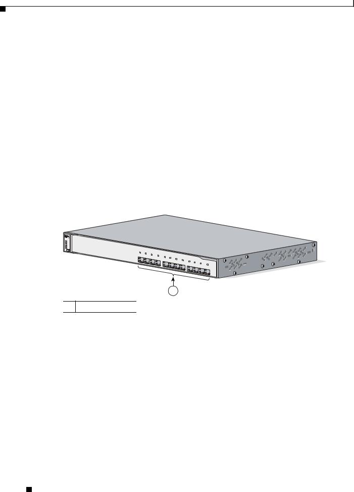
Catalyst 3750G-12S and Catalyst 3750G-12S-SD Switches Front Panel Description
The SFP module slots on the Catalyst 3750G-12S and Catalyst C3750G-12S-SD switches are numbered 1 through 12. The slots are grouped in three sets of four, as shown in Figure 1-6.
Figure 1-6 Catalyst 3750G-12S and Catalyst 3750G-12S-SD Front Panel
 SYST
SYST
RPS
MASTR
STAT
DUPLX
SPEED
STACK
MODE
1 2
3 4
5 6
7
8
Catalyst 3750
9 10 11 12
SERIES
97166
1
1 SFP module slots
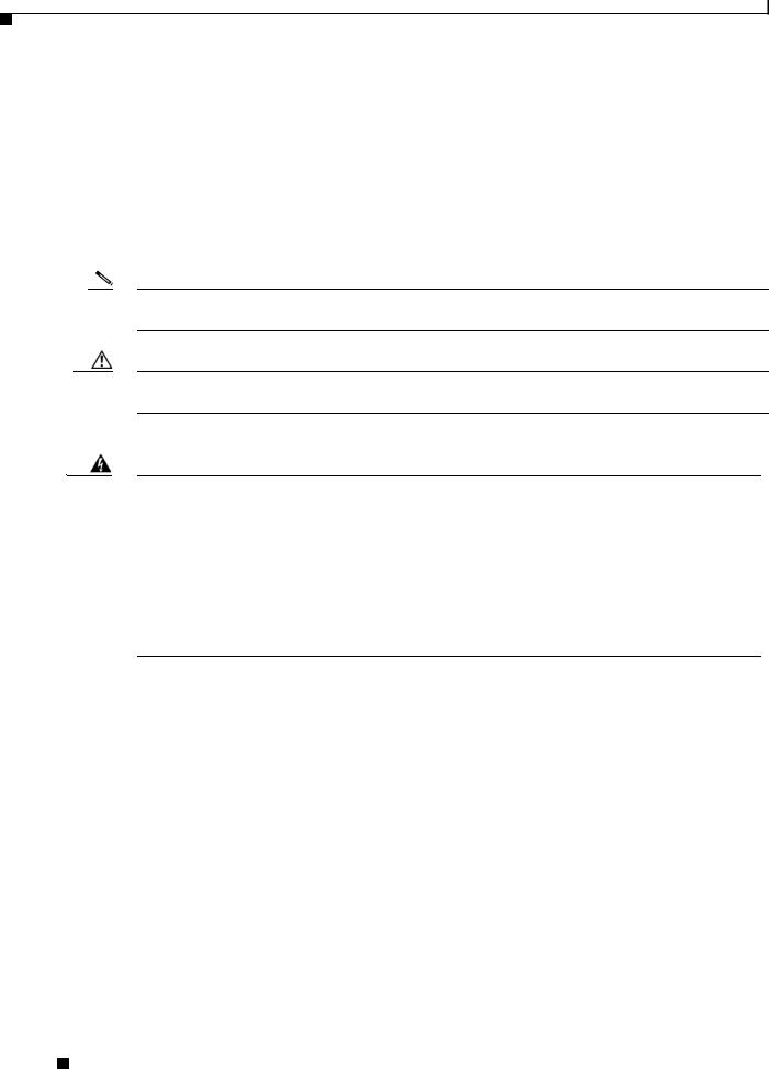
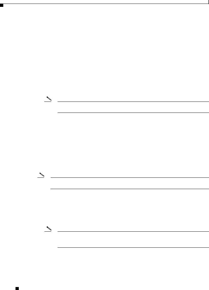
Catalyst 3750-24T, 3750G-24TS, and 3750G-24TS-1U Switches Front Panel Descriptions
The 10/100/1000 ports on the Catalyst 3750G-24T, 3750G-24TS, and 3750G-24TS-1U switches are grouped in pairs. The first member of the pair (port 1) is above the second member (port 2), as shown in Figure 1-7, Figure 1-8, and Figure 1-9. Port 3 is above port 4, and so on.
The SFP module slots are numbered 25 to 28 on the Catalyst 3750G-24TS Front Panel (Figure 1-8) and on the Catalyst 3750G-24TS-1U Front Panel (Figure 1-9).
Catalyst 3750 Switch Hardware Installation Guide
1-6 |
OL-6336-07 |
|
|

Chapter 1 Product Overview
Figure 1-7 Catalyst 3750G-24T Front Panel
SYST |
|
|
|
|
|
|
|
|
RPS |
1 |
2 |
|
|
|
|
|
|
MASTR |
|
3 |
4 |
6 |
|
|
|
|
STAT |
1X |
|
5 |
8 |
|
|
|
|
|
|
7 |
|
|
|
|||
DUPLX |
|
|
|
|
9 |
10 |
11 |
12 |
SPEED |
|
|
|
|
|
|
||
STACK |
|
|
|
|
|
|
|
|
MODE |
11X |
|
|
|
|
|
|
|
|
|
|
|
|
13 |
14 |
15 |
16 |
|
|
|
|
|
|
|
|
|
|
|
17 |
18 |
|
|
|
|
|
|
||
2X |
13X |
|
|
|
19 |
20 |
|
|
|
|
||
|
|
|
|
|
21 |
22 |
|
|
||||
|
|
|
|
|
|
|
|
|
|
|
23 |
24 |
12X |
23X |
Catalyst |
SERIES |
|
|
3750 |
|
|
14X |
|
|
|
24X |
|
|
1
1 10/100/1000 ports
Figure 1-8 Catalyst 3750G-24TS Front Panel
SYST |
|
|
|
|
|
|
|
|
RPS |
1 |
2 |
|
|
|
|
|
|
MASTR |
4 |
|
|
|
|
|
||
|
3 |
|
|
|
|
|
||
STAT |
1X |
|
5 |
6 |
8 |
|
|
|
DUPLX |
|
|
7 |
10 |
|
|
||
|
|
|
|
9 |
11 |
12 |
||
SPEED |
|
|
|
|
|
|
||
STACK |
|
|
|
|
|
|
|
|
MODE |
11X |
|
15 |
16 |
|
|
|
|
|
|
|
Catalyst 3750 |
|
|
13 |
14 |
|
|
|
|
|
|
|
|
|||
2X |
13X |
|
|
|
17 |
18 |
19 |
20 |
|
|
|
|
SERIES |
|
|
|
|
|
21 |
22 |
|
|
|
||||
|
|
|
|
|
|
|
|
|
|
|
23 |
24 |
|
|
12X |
|
|
|
|
|
|
|
|
|
|
23X |
|
|
|
|
|
|
|
|
|
|
|
|
|
25 |
|
|
14X |
|
|
|
|
|
|
|
|
|
|
26 |
|
|
|
|
|
|
|
|
|
|
|
|
|
27 |
|
|
|
|
|
|
|
|
|
|
|
|
|
28 |
|
|
|
|
|
|
|
|
|
|
|
|
|
24X |
|
1
2
1 10/100/1000 ports 2 SFP module slots
Figure 1-9 Catalyst 3750G-24TS-1U Front Panel
|
SYST |
|
|
|
|
|
|
|
|
|
|
|
|
|
|
|
|
|
|
|
|
|
|
|
|
RPS |
|
|
|
|
|
|
|
|
|
|
|
|
|
|
|
|
|
|
|
|
|
|
|
|
MASTR |
|
|
|
|
|
|
|
|
|
|
|
|
|
|
|
|
|
|
|
|
|
|
|
|
STAT |
|
|
|
|
|
|
|
|
|
|
|
|
|
|
|
|
|
|
|
|
|
|
|
|
DUPLX |
|
|
|
|
|
|
|
|
|
|
|
|
|
|
|
|
|
|
|
|
|
|
|
|
SPEED |
1 |
|
|
|
|
|
|
|
|
|
|
|
|
|
|
|
|
|
|
|
|
|
|
|
STACK |
2 |
4 |
|
|
|
|
|
|
|
|
|
|
|
|
|
|
|
|
|
|
|
|
|
|
|
3 |
6 |
|
|
|
|
|
|
|
|
|
|
|
|
|
|
|
|
|
|
|
||
MODE |
|
1X |
|
5 |
8 |
|
|
|
|
|
|
|
|
|
|
|
|
|
|
|
|
|
|
|
|
|
|
|
7 |
10 |
|
|
|
|
|
|
|
|
|
|
|
|
|
|
|
|
|
||
|
|
|
|
|
|
9 |
11 |
12 |
|
|
|
|
|
|
|
|
|
|
|
|
|
|
|
|
|
|
|
|
|
|
|
|
|
|
|
|
|
|
|
|
|
|
|
|
|
|
|
||
|
|
|
|
|
|
|
|
|
11X |
13 |
14 |
15 |
16 |
|
|
|
|
|
|
|
|
|
|
|
|
|
|
|
|
|
|
|
|
13X |
|
17 |
18 |
|
|
|
|
|
|
|
|
|
|||
|
|
2X |
|
|
|
|
|
|
|
|
|
|
|
|
|
19 |
20 |
21 |
22 |
23 |
24 |
Catalyst |
3750 |
|
|
|
|
|
|
|
|
|
|
|
|
|
|
|
|
|
|
|
|
|
|
|
|
SERIES |
|
|
|
|
|
|
|
|
|
|
|
|
|
|
|
|
|
|
|
|
|
|
23X |
|
|
|
|
|
|
|
|
|
|
|
|
12X |
|
|
|
|
|
|
|
|
|
|
|
|
25 |
|
27 |
|
|
|
|
|
|
|
|
|
|
14X |
|
|
|
|
|
|
|
|
|
|
|
|
|
|
|
|
|
|
|
|
|
|
|
|
|
|
|
|
|
|
|
|
|
|
|
24X |
26 |
|
28 |
1
2
1 10/100/1000 ports 2 SFP module slots
Front Panel Description
86543
86544
119768
Catalyst 3750 Switch Hardware Installation Guide
|
OL-6336-07 |
1-7 |
|
|
|
Chapter 1 Product Overview
Front Panel Description
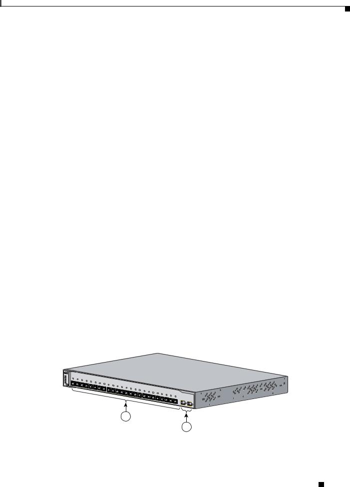
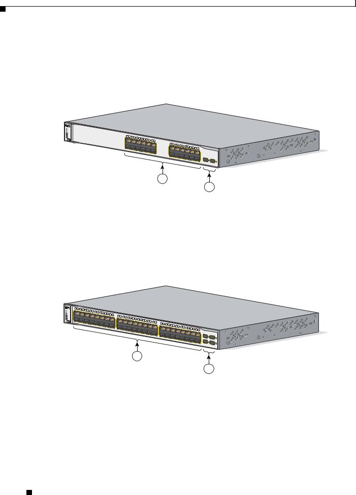
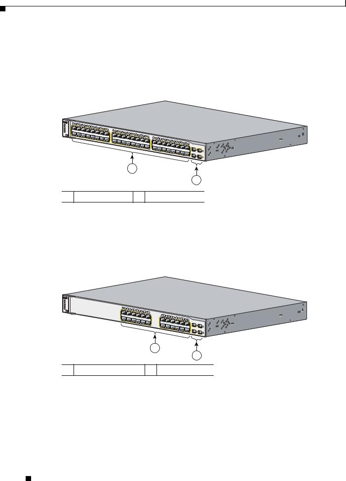
Catalyst 3750G-48TS Switch Front Panel Description
The 10/100/1000 ports on the Catalyst 3750G-48TS switch are numbered 1 through 48 and grouped in pairs. The first member of the pair (port 1) is above the second member (port 2), as shown in Figure 1-10. Port 3 is above port 4, and so on. The SFP module slots are numbered 49 to 52.
Figure 1-10 Catalyst 3750G-48TS Front Panel
SYST |
1 |
2 |
3 |
|
|
|
|
|
|
|
|
|
|
|
|
|
|
|
|
|
|
|
|
|
|
|
|
|
|
|
|
|
|
|
|
|
|
|
|
|
|
|
|
|
|
|
|
|
1X |
|
|
4 |
5 |
6 |
7 |
|
|
|
|
|
|
|
|
|
|
|
|
|
|
|
|
|
|
|
|
|
|
|
|
|
|
|
|
|
|
|
|
|
|
|
|
|
|
|
|
|
|
RPS |
|
|
|
|
8 |
9 |
|
|
|
|
|
|
|
|
|
|
|
|
|
|
|
|
|
|
|
|
|
|
|
|
|
|
|
|
|
|
|
|
|
|
|
|
|
|
|
|||
MASTR |
|
|
|
|
|
|
|
|
|
10 |
11 |
12 |
13 |
|
|
|
|
|
|
|
|
|
|
|
|
|
|
|
|
|
|
|
|
|
|
|
|
|
|
|
|
|
|
|
|
|
|
|
STAT |
|
|
|
|
|
|
|
|
|
|
|
14 |
15 |
16 |
|
|
|
|
|
|
|
|
|
|
|
|
|
|
|
|
|
|
|
|
|
|
|
|
|
|
|
|
|
|
|
|
||
DUPLX |
|
|
|
|
|
|
|
|
|
|
|
|
|
|
|
|
|
|
|
|
|
|
|
|
|
|
|
|
|
|
|
|
|
|
|
|
|
|
|
|
|
|
|
|
|
|
|
|
SPEED |
|
|
|
|
|
|
|
|
|
|
|
|
|
|
|
17 |
18 |
19 |
20 |
21 |
|
|
|
|
|
|
|
|
|
|
|
|
|
|
|
|
|
|
|
|
|
|
|
|
|
|
|
|
STACK |
|
|
|
|
|
|
|
|
|
|
|
|
|
|
|
15X 17X |
|
|
|
22 |
23 |
24 |
25 |
|
|
|
|
|
|
|
|
|
|
|
|
|
|
|
|
|
|
|
|
|
|
|
|
|
|
|
|
|
|
|
|
|
|
|
|
|
|
|
|
|
|
|
|
|
|
|
26 |
27 |
|
|
|
|
|
|
|
|
|
|
|
|
|
|
|
|
|
|
|
|
|
|
|||
MODE |
2X |
|
|
|
|
|
|
|
|
|
|
|
|
|
|
|
|
|
|
|
|
|
|
28 |
29 |
|
|
|
|
|
|
|
|
|
|
|
|
|
|
|
|
|
|
|
|
|||
|
|
|
|
|
|
|
|
|
|
|
|
|
|
|
|
|
|
|
|
|
|
|
|
|
|
|
|
30 |
31 |
32 |
|
|
|
|
|
|
|
|
|
|
|
|
|
|
|
|
|
|
|
|
|
|
|
|
|
|
|
|
|
|
|
|
|
|
|
|
|
|
|
|
|
|
|
|
|
|
|
|
|
33 |
34 |
35 |
36 |
37 |
|
|
|
|
|
|
|
|
|
|
|
|
|
|
|
|
|
|
|
|
|
|
|
|
|
|
|
|
|
|
|
|
|
|
|
|
|
|
|
|
|
|
|
|
31X 33X |
|
38 |
39 |
|
|
|
|
|
|
|
|
|
|
|
|||
|
|
|
|
|
|
|
|
|
|
|
|
|
|
|
|
|
|
|
|
|
|
|
|
|
|
|
|
|
|
|
|
|
|
40 |
41 |
|
|
|
|
|
|
|
|
|
||||
|
|
|
|
|
|
|
|
|
|
|
|
|
|
|
|
16X 18X |
|
|
|
|
|
|
|
|
|
|
|
|
|
|
|
|
|
|
|
|
|
|
42 |
43 |
44 |
45 |
|
|
|
Catalyst |
|
|
|
|
|
|
|
|
|
|
|
|
|
|
|
|
|
|
|
|
|
|
|
|
|
|
|
|
|
|
|
|
|
|
|
|
|
|
|
|
|
|
46 |
47 |
48 |
3750G SERIES |
|||||
|
|
|
|
|
|
|
|
|
|
|
|
|
|
|
|
|
|
|
|
|
|
|
|
|
|
|
|
|
|
|
|
|
|
|
|
|
|
|
|
|
|
|
|
|
|
|
|
|
|
|
|
|
|
|
|
|
|
|
|
|
|
|
|
|
|
|
|
|
|
|
|
|
|
|
|
|
|
|
|
|
|
|
|
|
|
|
|
|
|
|
|
|
|
|
47X |
|
|
|
|
|
|
|
|
|
|
|
|
|
|
|
|
|
|
|
|
|
|
|
|
|
|
|
|
|
|
|
|
|
32X 34X |
|
|
|
|
|
|
|
|
|
|
|
|
|
|
|
49 |
|
|
|
|
|
|
|
|
|
|
|
|
|
|
|
|
|
|
|
|
|
|
|
|
|
|
|
|
|
|
|
|
|
|
|
|
|
|
|
|
|
|
|
|
|
|
|
|
51 |
|
|
|
|
|
|
|
|
|
|
|
|
|
|
|
|
|
|
|
|
|
|
|
|
|
|
|
|
|
|
|
|
|
|
|
|
|
|
|
|
|
|
|
|
|
|
|
|
|
|
|
|
|
|
|
|
|
|
|
|
|
|
|
|
|
|
|
|
|
|
|
|
|
|
|
|
|
|
|
|
|
|
|
|
|
|
|
|
|
|
|
|
|
|
|
|
48X |
50 |
52 |
|
|
|
|
|
|
|
|
|
|
|
|
|
|
|
|
|
|
|
|
|
|
|
|
|
|
|
|
|
|
|
|
|
|
|
|
|
|
|
|
|
|
|
|
|
|
|
|
1
2
119770
1 10/100/1000 ports 2 SFP module slots
Catalyst 3750G-24PS Switch Front Panel Description
The 10/100/1000 PoE ports on the Catalyst 3750G-24PS switch are grouped in pairs. The first member of the pair (port 1) is above the second member (port 2), as shown in Figure 1-11. Port 3 is above port 4, and so on. The SFP module slots are numbered 25 to 28.
Figure 1-11 Catalyst 3750G-24PS Switch Front Panel
SYST |
|
|
|
|
|
|
|
|
|
|
|
|
|
|
|
|
|
|
|
|
|
|
|
RPS |
|
|
|
|
|
|
|
|
|
|
|
|
|
|
|
|
|
|
|
|
|
|
|
MASTR |
|
|
|
|
|
|
|
|
|
|
|
|
|
|
|
|
|
|
|
|
|
|
|
STAT |
|
|
|
|
|
|
|
|
|
|
|
|
|
|
|
|
|
|
|
|
|
|
|
DUPLX |
|
|
|
|
|
|
|
|
|
|
|
|
|
|
|
|
|
|
|
|
|
|
|
SPEED |
1 |
|
|
|
|
|
|
|
|
|
|
|
|
|
|
|
|
|
|
|
|
|
|
STACK |
2 |
4 |
|
|
|
|
|
|
|
|
|
|
|
|
|
|
|
|
|
|
|
|
|
|
3 |
|
|
|
|
|
|
|
|
|
|
|
|
|
|
|
|
|
|
|
|
||
PoE |
1X |
|
5 |
6 |
8 |
|
|
|
|
|
|
|
|
|
|
|
|
|
|
|
|
|
|
MODE |
|
|
|
7 |
10 |
|
|
|
|
|
|
|
|
|
|
|
|
|
|
|
|
|
|
|
|
|
|
|
9 |
11 |
12 |
|
|
|
|
|
|
|
|
|
|
|
|
|
|
|
|
|
|
|
|
|
|
|
|
11X |
13 |
14 |
15 |
16 |
|
|
|
|
|
|
|
|
|
|
|
|
|
|
|
|
|
|
|
13X |
|
17 |
18 |
|
|
|
|
|
|
|
|
|
|||
|
|
|
|
|
|
|
|
|
|
|
|
19 |
20 |
|
|
|
|
Catalyst |
|
|
|||
|
2X |
|
|
|
|
|
|
|
|
|
|
|
|
|
|
|
21 |
22 |
23 |
24 |
3750G |
SERIES PoE-24 |
|
|
|
|
|
|
|
|
|
|
|
|
|
|
|
|
|
|
|
|
|
|
|
|
|
|
|
|
|
|
|
|
|
|
|
|
|
|
|
|
|
|
|
|
|
23X |
|
|
|
|
|
|
|
|
|
|
|
12X |
|
|
|
|
|
|
|
|
|
|
|
|
|
25 |
27 |
|
|
|
|
|
|
|
|
|
14X |
|
|
|
|
|
|
|
|
|
|
|
|
|
|
|
|
|
|
|
|
|
|
|
|
|
|
|
|
|
|
|
|
|
|
24X |
|
26 |
28 |
|
|
|
|
|
|
|
|
|
|
|
|
|
|
|
|
|
|
|
|
|
|
|
1
2
1 10/100/1000 PoE ports 2 SFP module slots
119769
Catalyst 3750 Switch Hardware Installation Guide
1-8 |
OL-6336-07 |
|
|
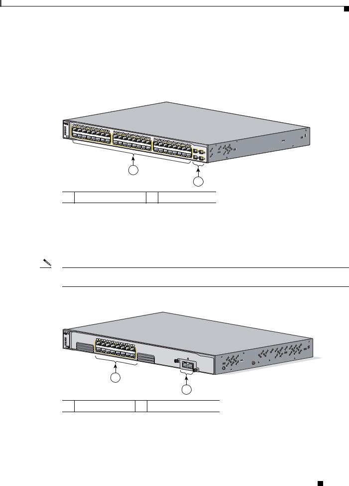
Chapter 1 Product Overview
Front Panel Description
Catalyst 3750G-48PS Switch Front Panel Description
The 10/100/1000 PoE ports on the Catalyst 3750G-48PS switch are grouped in pairs. The first member of the pair (port 1) is above the second member (port 2), as shown in Figure 1-12. Port 3 is above port 4, and so on. The SFP module slots are numbered 49 to 52.
Figure 1-12 Catalyst 3750G-48PS Switch Front Panel
 SYST RPS
MASTR STAT
DUPLX SPEED STACK PoE MODE
1X
2X
1 |
2 |
3 |
4 |
|
|
|
|
|
|
|
|
|
|
|
|
|
|
5 |
6 |
|
|
|
|
|
|
|
|
|
|
||
|
|
|
|
7 |
8 |
|
|
|
|
|
|
|
|
||
|
|
|
|
|
|
|
|
9 |
10 |
11 |
12 |
13 |
|
|
|
|
|
|
|
|
|
|
|
|
|
14 |
15 |
|
|||
|
|
|
|
|
|
|
|
|
|
|
|
|
|
16 |
17 |
18 |
19 |
20 |
21 |
|
|
|
|
|
|
|
|
|
|
|
|
|
|
|
|
|
|
|
|
|
|
|
|
|
|
|
|
|
15X 17X |
|
22 |
23 |
|
|
|
|
|
|
|
|
|
|
|
|
|
|
|
|
|
|
|
|
|
|
|
|
|
|
|
|||
|
|
|
|
|
|
24 |
25 |
26 |
27 |
|
|
|
|
|
|
|
|
|
|
|
|
|
|
|
|
|
|
|
|
|
|
|
|
|
|
|
|
|
|
|
|
28 |
29 |
|
|
|
|
|
|
|
|
|
|
|
|
|
|
|
|
|
|
|
|
|
|||
|
|
|
|
|
|
|
|
|
|
|
|
30 |
31 |
32 |
|
|
|
|
|
|
|
|
|
|
|
|
|
|
|
|
|
|
|
|
|
|
|
|
|
|
|
|
|
|
|
|
|
|
33 |
34 |
35 |
36 |
37 |
|
|
|
|
|
|
|
|
|
|
|
|
|
|
|
|
|
|
|
|
|
|
|
|
|
|
|
|
|
31X 33X |
|
38 |
39 |
|
|
|
|
|
|
|
|
|
|
|
|
|||
|
|
|
|
|
|
|
|
|
|
|
|
|
|
|
|
|
|
40 |
41 |
|
|
|
|
|
|
|
|
|
|
||||
16X 18X |
|
|
|
|
|
|
|
|
|
|
|
|
|
|
|
|
|
|
|
|
|
|
42 |
43 |
44 |
45 |
|
|
|
Catalyst |
|
|
|
|
|
|
|
|
|
|
|
|
|
|
|
|
|
|
|
|
|
|
|
|
|
|
|
46 |
47 |
|
3750G |
|
|||||
|
|
|
|
|
|
|
|
|
|
|
|
|
|
|
|
|
|
|
|
|
|
|
|
|
|
|
48 |
SERIES PoE-48 |
|||||
|
|
|
|
|
|
|
|
|
|
|
|
|
|
|
|
|
|
|
|
|
|
|
|
|
|
|
|
|
|
|
|
|
|
|
|
|
|
|
|
|
|
|
|
|
|
|
|
|
|
|
|
|
|
|
|
|
|
|
|
|
|
|
|
47X |
|
|
|
|
|
|
|
|
|
|
|
|
|
|
|
|
|
|
32X 34X |
|
|
|
|
|
|
|
|
|
|
|
|
|
|
|
|
49 |
|
|
|
|
|
|
|
|
|
|
|
|
|
|
|
|
|
|
|
|
|
|
|
|
|
|
|
|
|
|
|
|
|
51 |
|
|
|
|
|
|
|
|
|
|
|
|
|
|
|
|
|
|
|
|
|
|
|
|
|
|
|
|
|
|
|
|
|
|
|
|
|
|
|
|
|
|
|
|
|
|
|
|
|
|
|
|
|
|
|
|
|
|
|
|
|
|
|
|
|
48X |
|
50 |
52 |
|
|
|
|
|
|
|
|
|
|
|
|
|
|
|
|
|
|
|
|
|
|
|
|
|
|
|
|
|
|
|
|
|
1
2
1 10/100/1000 PoE ports 2 SFP module slots
Catalyst 3750G-16TD Switch Front Panel Description
The 10/100/1000 ports on the Catalyst 3750G-16TD switch are grouped in pairs. The first member of the pair (port 1) is above the second member (port 2), as shown in Figure 1-13. Port 3 is above port 4, and so on. The XENPAK module slot is numbered 1.
Note The 10-Gigabit Ethernet XENPAK modules are referred to as 10-Gigabit Ethernet module ports in the software documentation.
Figure 1-13 Catalyst 3750G-16TD Switch Front Panel
 SYST RPS
MASTR STAT
DUPLX SPEED STACK MODE
1 |
2 |
4 |
|
|
|
|
|
|
|
|
|
3 |
6 |
|
|
|
|
|
|
|
|
1X |
|
5 |
7 |
8 |
|
|
|
|
|
|
|
|
|
|
|
9 |
10 |
12 |
|
|
|
|
|
|
|
|
|
11 |
13 |
14 |
|
|
|
|
|
|
|
|
|
|
|
15 |
16 |
|
|
|
|
|
|
|
|
|
|
15X |
2X |
|
|
|
|
|
|
|
|
|
|
|
|
|
|
|
|
|
|
|
|
16X |
1
Catalyst 3750 series
|
1 |
TX |
RX |
2
104572
1 10/100/1000 ports 2 XENPAK module slot
Catalyst 3750 Switch Hardware Installation Guide
|
OL-6336-07 |
1-9 |
|
|
|
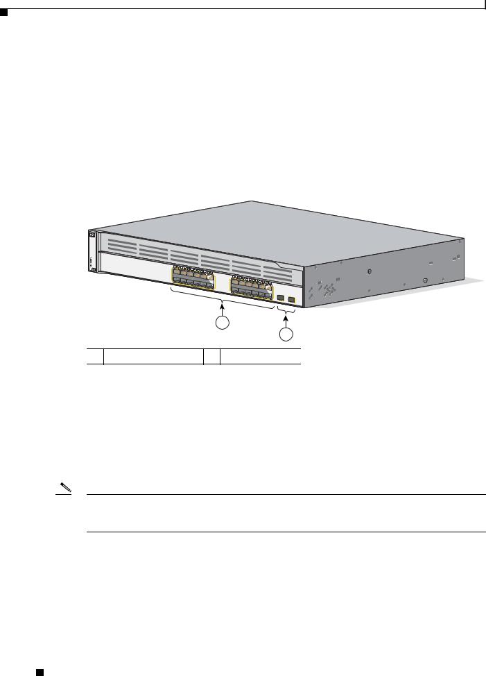
Chapter 1 Product Overview
10/100 and 10/100/1000 Ports
Catalyst 3750G Integrated Wireless LAN Controller Switch Front Panel Description
The Catalyst 3750G Integrated Wireless LAN Controller switches have an integrated Cisco wireless LAN controller. Depending on the switch model, the integrated wireless controller can support up to 25 or 50 Cisco Lightweight Access Points. The 10/100/1000 PoE ports on the Catalyst 3750G-24WS-S25 and the 3750G-24WS-S50 switch are numbered 1 through 24 and grouped in pairs. The first member of the pair (port 1) is above the second member (port 2), as shown in Figure 1-14. Port 3 is above port 4, and so on. The SFP module slots are numbered 25 and 26. The switch also has two internal Gigabit Ethernet ports that connect the switch and the controller. The internal ports are numbered as ports 27 and 28 and are not visible on the front panel.
Figure 1-14 Catalyst 3750G-24WS-S25 and 3750G-24WS-S50 Switches Front Panel
 SYST RPS MASTR STAT DUPLX SPEED STACK PoE
1 |
2 |
|
|
|
|
|
|
|
|
|
|
|
|
|
Catalyst |
3750G |
SERIES PoE-24 |
||
1X |
|
3 |
4 |
6 |
|
|
|
|
|
|
|
|
|
|
Wireless |
|
|||
|
|
5 |
|
|
|
|
|
|
|
|
|
|
|
|
LAN C |
ontroller |
|||
|
|
|
|
7 |
8 |
10 |
|
|
|
|
|
|
|
|
|
|
|
|
|
|
|
|
|
|
9 |
12 |
|
|
|
|
|
|
|
|
|
|
|
|
|
|
|
|
|
|
|
11 |
|
|
|
|
|
|
|
|
|
|
|
|
|
|
|
|
|
|
|
|
11X |
13 |
14 |
16 |
|
|
|
|
|
|
|
|
|
|
|
|
|
|
|
|
13X |
|
15 |
|
|
|
|
|
|
|
|
|
|
|
|
|
|
|
|
|
|
|
17 |
18 |
20 |
|
|
|
|
|
|
|
|
2X |
|
|
|
|
|
|
|
|
|
|
19 |
22 |
|
|
|
|
|
|
|
|
|
|
|
|
|
|
|
|
|
|
21 |
24 |
|
|
|
|
|
||
|
|
|
|
|
|
|
|
|
|
|
|
|
23 |
|
|
|
|
|
|
|
|
|
|
|
|
|
|
|
|
|
|
|
|
23X |
|
|
|
|
|
|
|
|
|
|
|
|
12X |
|
|
|
|
|
|
|
|
|
|
|
|
|
|
|
|
|
|
|
14X |
|
|
|
|
|
|
|
|
|
|
|
|
|
|
|
|
|
|
|
|
|
|
|
|
|
|
24X |
25 |
|
|
|
|
1
2
141726
1 10/100/1000 PoE ports 2 SFP module slots
10/100 and 10/100/1000 Ports
You can set the 10/100 ports on the Catalyst 3750 switches to operate in any combination of half duplex, full duplex, 10 Mb/s, or 100 Mb/s. You can set the 10/100/1000 ports to operate in 10 or 100 Mb/s in half or full duplex, or in 1000 Mb/s in full duplex.
You can set both the 10/100 and the 10/100/1000 ports for speed and duplex autonegotiation, in compliance with IEEE 802.3AB. (The default setting is autonegotiate.)
Note You can configure duplex mode to half, full, or autonegotiate on Gigabit Ethernet interfaces if the speed is set to 10 or 100 Mb/s. You cannot configure half-duplex mode on Gigabit Ethernet interfaces if the interface speed is 1000 Mb/s.
When set for autonegotiation, the port senses the speed and duplex settings of the attached device and advertises its own capabilities. If the connected device also supports autonegotiation, the switch port negotiates the best connection (the fastest line speed that both devices support and full-duplex transmission if the attached device supports it) and configures itself accordingly. In all cases, the attached device must be within 328 feet (100 meters).
Catalyst 3750 Switch Hardware Installation Guide
1-10 |
OL-6336-07 |
|
|
Chapter 1 Product Overview
10/100 and 10/100/1000 Ports
Warning Voltages that present a shock hazard may exist on Power over Ethernet (PoE) circuits if interconnections are made using uninsulated exposed metal contacts, conductors, or terminals. Avoid using such interconnection methods, unless the exposed metal parts are located within a restricted access location and users and service people who are authorized within the restricted access location are made aware of the hazard. A restricted access area can be accessed only through the use of a special tool, lock and key or other means of security. Statement 1072
The 10/100 ports on the Catalyst 3750-24PS and 3750-48PS switches and the 10/100/1000 ports on the Catalyst 3750G-24PS, 3750G-48PS, 3750G-24WS-S25, and 3750G-24WS-S50 switches provide PoE support for devices that are compliant with IEEE 802.3af. They also provide Cisco pre-standard PoE support for Cisco IP Phones and Cisco Aironet Access Points.
Each of the Catalyst 3750-24PS switch 10/100 ports or the Catalyst 3750G-24PS switch 10/100/1000 ports can deliver up to 15.4 W of PoE. On the Catalyst 3750-48PS or 3750G-48PS switches, any 24 of the 48 10/100 or 10/100/1000 ports can deliver 15.4 W of PoE, or any combination of the ports can deliver an average of 7.7 W of PoE at the same time, up to a maximum switch power output of 370 W.
Each of the Catalyst 3750G-24WS-S25 and 3750G-24WS-S50 switch 10/100/1000 ports can deliver up to 15.4 W of PoE.
On a per-port basis, you can control whether a Catalyst 3750 PoE port automatically provides power when an IP phone or an access point is connected. The device manager and the CLI provide two PoE settings for each 10/100 or 10/100/1000 PoE port: Auto (the default) and Never.
•When you select Auto, the port only provides power if a valid powered device, such as an
IEEE 802.3af-compliant powered device, a Cisco pre-standard IP phone, or a Cisco pre-standard Cisco access point, is connected to it.
•When you select Never, the port does not provide power even if a Cisco IP phone or an access point is connected to it. For information about configuring and monitoring PoE ports, see the device manager online help and the switch software configuration guide.
Cisco enhanced power negotiation allows some powered devices, such as the Cisco 7970G IP Phone, to operate in high-power mode on Catalyst 3750 PoE switches. The powered device and the switch negotiate through power-negotiation Cisco Discovery Protocol (CDP) messages for an agreed-upon power-consumption level. The negotiation allows a high-power Cisco powered device that consumes more than 7 W to operate at its highest power mode. The powered device first boots up in low-power mode, consumes less than 7 W, and negotiates to obtain enough power to operate in high-power mode. The device changes to high-power mode only when it receives confirmation from the switch. High-power devices can operate in low-power mode on switches that do not support power-negotiation CDP.
For information about configuring and monitoring PoE ports, see the device manager online help and the switch software configuration guide.
Note You also can connect a Cisco IP Phone or Cisco Aironet Access Point to a Catalyst 3750 PoE switch 10/100 or 10/100/1000 port and to an AC power source for redundant power. The powered device might change to the AC power source as its primary power source when connected to it. In that case, the PoE port becomes the backup power source for the powered device.
If the primary source fails, the second power source becomes the primary power source to the powered device. During the power transfer, an IP Phone might reboot or reestablish link with the switch.
Catalyst 3750 Switch Hardware Installation Guide
|
OL-6336-07 |
1-11 |
|
|
|

Chapter 1 Product Overview
10/100 and 10/100/1000 Ports
For information about Cisco IP Phones and Cisco Aironet Access Points, see the documentation that came with your IP phone or access point.
Note 100BASE-TX and 1000BASE-T traffic requires a Category 5 or later cable. 10BASE-T traffic can use Category 3 or Category 4 cables.
When you connect the switch to workstations, servers, routers, and Cisco IP Phones, be sure that the cable is a straight-through cable. When you connect the switch to switches or hubs, use a crossover cable. When using a straight-through or crossover cable for 1000BASE-T connections, be sure to use a twisted four-pair, Category 5 or later cable for proper operation. Pinouts for the cables are described in Appendix A, “Technical Specifications.”
You can use the mdix auto interface configuration command in the CLI to enable the automatic medium-dependent interface crossover (auto-MDIX) feature. When you enable the auto-MDIX feature, the switch detects the required cable type for copper Ethernet connections and configures the interfaces accordingly. Therefore, you can use either a crossover or a straight-through cable for connections to a copper 10/100, 10/100/1000, or 1000BASE-T SFP module port on the switch, no matter what type of device is on the other end of the connection.
The auto-MDIX feature is enabled by default on switches running Cisco IOS Release 12.2(18)SE or later. For releases between Cisco IOS Release 12.1(14)EA1 and 12.2(18)SE, the auto-MDIX feature is disabled by default. For configuration information for this feature, see the switch software configuration guide or the switch command reference.
Many legacy powered devices, including older Cisco IP phones and access points that do not fully support IEEE 802.3af, might not support PoE when connected to the switches by a crossover cable.
100BASE-FX Ports
The 100BASE-FX ports use 50/125or 62.5/125-micron multimode fiber-optic cabling. In full-duplex mode, the cable length from a switch to an attached device cannot exceed 6,562 feet (2 kilometers).
The 100BASE-FX ports operate only at 100 Mb/s in either fullor half-duplex mode and do not support autonegotiation. The half-duplex mode is the default setting.
You can connect a 100BASE-FX port to an SC or ST port on a target device by using one of the MT-RJ fiber-optic patch cables that are listed in Table B-1 on page B-3.
SFP Module Slots
Catalyst 3750 switches with SFP module slots support these SFP modules:
•100BASE-FX (MMF)
•1000BASE-BX
•1000BASE-LX
•1000BASE-SX
•1000BASE-ZX
Catalyst 3750 Switch Hardware Installation Guide
1-12 |
OL-6336-07 |
|
|

Chapter 1 Product Overview
10/100 and 10/100/1000 Ports
•1000BASE-T
•CWDM
For a list of the SFP modules that the switches support, see the Catalyst 3750 switch release notes.
SFP Modules
The Catalyst 3750 switch uses Gigabit Ethernet SFP modules to establish connections to other devices. These transceiver modules are field-replaceable, providing the uplink interfaces when inserted in an SFP module slot. You can use the SFP modules for Gigabit uplink connections to other switches. You use fiber-optic cables with LC or MT-RJ connectors to connect to a fiber-optic SFP module. You use a Category 5 or higher cable with RJ-45 connectors to connect to a copper SFP module.
For more information about these SFP modules, see your SFP module documentation.
XENPAK Module Slot (Catalyst 3750G-16TD Switch)
The Catalyst 3750G-16TD switch uses 10-Gigabit Ethernet XENPAK modules to establish connections to networks. You install the modules in the module slot in the switch front panel. See Table B-2 on page B-4 for a list of XENPAK modules that the Catalyst 3750G-16TD switch supports.
Note The 10-Gigabit Ethernet XENPAK modules are referred to as 10-Gigabit Ethernet module ports in the software documentation.
LEDs
You can use the switch LEDs to monitor switch activity and its performance. Figure 1-15, Figure 1-16, and Figure 1-17 show the switch LEDs and the Mode button that you use to select one of the port modes.
All LEDs are visible through the GUI management applications—the Network Assistant application for multiple switches and the device manager GUI for a single switch. The switch software configuration guide describes how to use the command-line interface (CLI) to configure and monitor individual switches and switch clusters.
Catalyst 3750 Switch Hardware Installation Guide
|
OL-6336-07 |
1-13 |
|
|
|
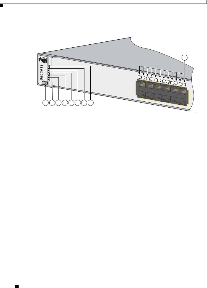
Chapter 1 Product Overview
10/100 and 10/100/1000 Ports
Figure 1-15 Catalyst 3750-24TS, 3750G-24T, 3750G-16TD, 3750-48TS, 3750G-48TS, 3750G-24TS, and 3750G-24TS-1U Switch LEDs
9
SYST |
|
|
|
|
|
|
|
RPS |
|
|
|
|
|
|
|
MASTR |
|
|
|
|
|
|
|
STAT |
|
|
|
|
|
|
|
DUPLX |
|
|
|
|
|
|
|
SPEED |
|
|
|
|
|
|
|
STACK |
|
|
|
|
|
|
|
MODE |
|
|
|
|
|
|
|
1 |
2 |
3 |
4 |
5 |
6 |
7 |
8 |
86545
1 |
Mode button |
6 |
Master LED |
|
|
|
|
2 |
Stack LED |
7 |
RPS LED |
|
|
|
|
3 |
Speed LED |
8 |
System LED |
|
|
|
|
4 |
Duplex LED |
9 |
Port LED |
|
|
|
|
5 |
Status LED |
|
|
|
|
|
|
Catalyst 3750 Switch Hardware Installation Guide
1-14 |
OL-6336-07 |
|
|
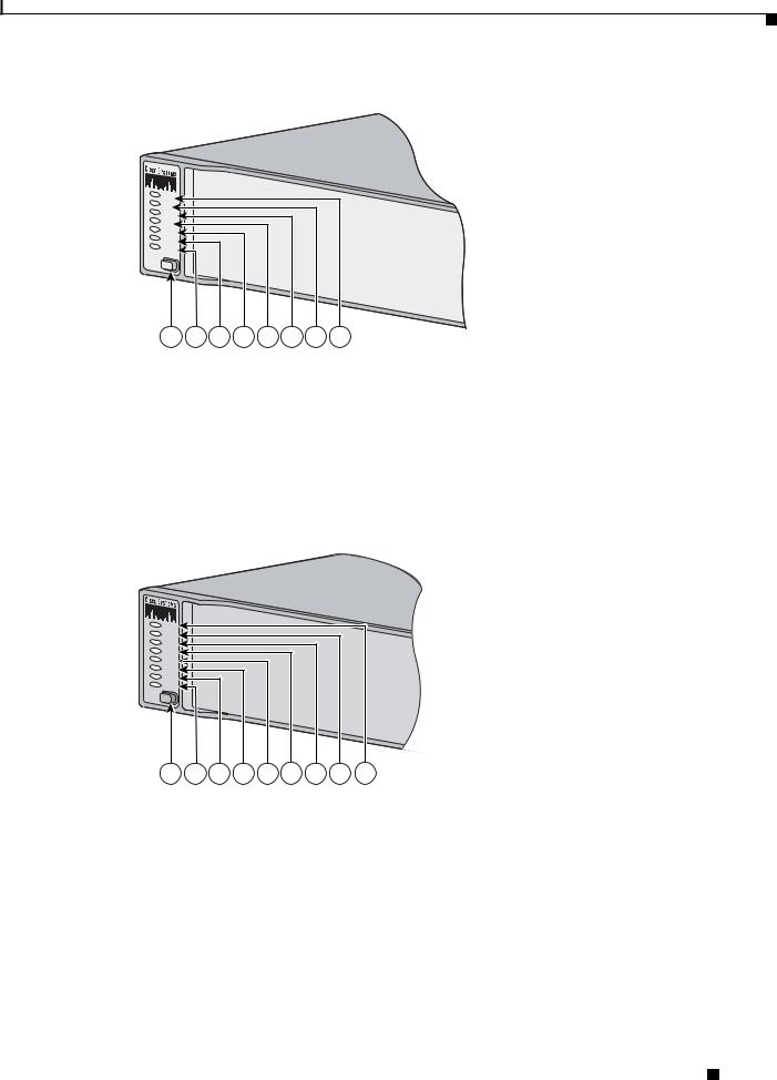
Chapter 1 Product Overview
10/100 and 10/100/1000 Ports
Figure 1-16 Catalyst 3750G-12S and Catalyst 3750G-12S-SD Switch LEDs
SYST |
|
|
|
|
|
|
|
RPS |
|
|
|
|
|
|
|
MASTR |
|
|
|
|
|
|
|
STAT |
|
|
|
|
|
|
|
DUPLX |
|
|
|
|
|
|
|
SPEED |
|
|
|
|
|
|
|
STACK |
|
|
|
|
|
|
|
MODE |
|
|
|
|
|
|
|
1 |
2 |
3 |
4 |
5 |
6 |
7 |
132966 |
8 |
1 |
Mode button |
5 |
Status LED |
|
|
|
|
2 |
Stack LED |
6 |
Master LED |
|
|
|
|
3 |
Speed LED |
7 |
RPS LED1 |
4 |
Duplex LED |
8 |
System LED |
|
|
|
|
1.The RPS LED is not used on the Catalyst 3750G-12S-SD switch.
Figure 1-17 Catalyst 3750-24PS, 3750G-24PS, 3750-48PS, and 3750G-48PS Switch LEDs
SYST |
|
|
|
|
|
|
|
|
RPS |
|
|
|
|
|
|
|
|
MASTR |
|
|
|
|
|
|
|
|
STAT |
|
|
|
|
|
|
|
|
DUPLX |
|
|
|
|
|
|
|
|
SPEED |
|
|
|
|
|
|
|
|
STACK |
|
|
|
|
|
|
|
|
PoE |
|
|
|
|
|
|
|
|
MODE |
|
|
|
|
|
|
|
|
|
|
|
|
|
|
|
|
104062 |
1 |
2 |
3 |
4 |
5 |
6 |
7 |
8 |
9 |
1 |
Mode button |
6 |
Status LED |
|
|
|
|
2 |
PoE LED |
7 |
Master LED |
|
|
|
|
3 |
Stack LED |
8 |
RPS LED |
|
|
|
|
4 |
Speed LED |
9 |
System LED |
|
|
|
|
5 |
Duplex LED |
|
|
|
|
|
|
Catalyst 3750 Switch Hardware Installation Guide
|
OL-6336-07 |
1-15 |
|
|
|
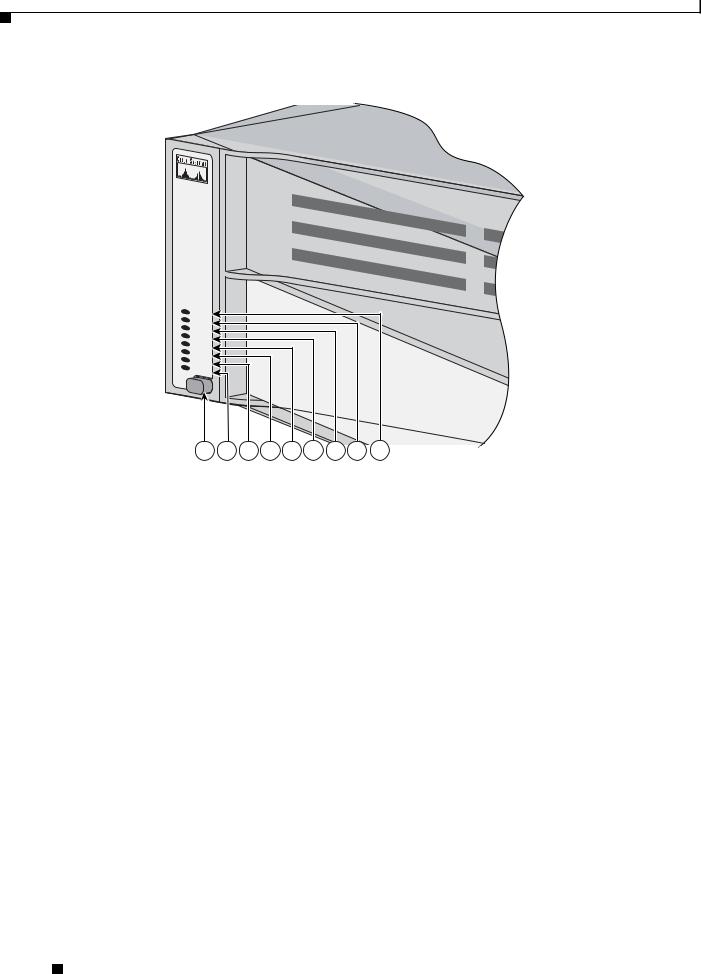
Chapter 1 Product Overview
10/100 and 10/100/1000 Ports
Figure 1-18 Catalyst 3750G-24WS-S25 and 3750G-24WS-S50 Switch LEDs
SYST |
|
|
|
|
|
|
|
|
RPS |
|
|
|
|
|
|
|
|
MASTR |
|
|
|
|
|
|
|
|
STAT |
|
|
|
|
|
|
|
|
DUPLX |
|
|
|
|
|
|
|
|
SPEED |
|
|
|
|
|
|
|
|
ST |
|
|
|
|
|
|
|
|
ACK |
|
|
|
|
|
|
|
|
PoE |
|
|
|
|
|
|
|
|
1 |
2 |
3 |
4 |
5 |
6 |
7 |
8 |
141727 |
9 |
1 |
Mode button |
6 |
Status LED |
|
|
|
|
2 |
PoE LED |
7 |
Master LED |
|
|
|
|
3 |
Stack LED |
8 |
RPS LED |
|
|
|
|
4 |
Speed LED |
9 |
System LED |
|
|
|
|
5 |
Duplex LED |
|
|
|
|
|
|
Catalyst 3750 Switch Hardware Installation Guide
1-16 |
OL-6336-07 |
|
|

Chapter 1 Product Overview
10/100 and 10/100/1000 Ports
System LED
The System LED shows whether the system is receiving power and is functioning properly.
Table 1-1 lists the LED colors and their meanings.
Table 1-1 |
System LED |
|
|
|
|
Color |
|
System Status |
|
|
|
Off |
|
System is not powered on. |
|
|
|
Green |
|
System is operating normally. |
|
|
|
Amber |
|
System is receiving power but is not functioning properly. |
|
|
|
Alternating green and amber1 |
Wireless controller is not functioning properly. |
|
1. Applies only to the Catalyst 3750G-24WS-S25 and 3750G-24WS-S50 switches.
For information on the System LED colors during power-on self-test (POST), see the “Powering On the Switch and Running POST” section on page 2-7.
RPS LED
The RPS LED shows the RPS status. Table 1-2 lists the LED colors and their meanings. The RPS LED is not used on the Catalyst 3750G-12S-SD switch.
Table 1-2 |
RPS LED |
|
|
|
|
Color |
|
RPS Status |
|
|
|
Off |
|
RPS is off or not properly connected. |
|
|
|
Green |
|
RPS is connected and ready to provide back-up power, if required. |
|
|
|
Flashing green |
|
RPS is connected but is unavailable because it is providing power to another device |
|
|
(redundancy has been allocated to a neighboring device). |
|
|
|
Amber |
|
The RPS is in standby mode or in a fault condition. Press the Standby/Active button |
|
|
on the RPS, and the LED should turn green. If it does not, the RPS fan could have |
|
|
failed. Contact Cisco Systems. |
|
|
|
Flashing amber |
|
The internal power supply in a switch has failed, and the RPS is providing power |
|
|
to the switch (redundancy has been allocated to this device). |
|
|
|
For more information about the Cisco RPS 2300, see the Cisco Redundant Power System 2300 Hardware Installation Guide. For more information about the Cisco RPS 675, see the Cisco RPS 675 Redundant Power System Hardware Installation Guide. These guides are available on Cisco.com.
Catalyst 3750 Switch Hardware Installation Guide
|
OL-6336-07 |
1-17 |
|
|
|

Chapter 1 Product Overview
10/100 and 10/100/1000 Ports
Master LED
The Master LED shows the stack master status. Table 1-2 lists the LED colors and their meanings.
Table 1-3 |
Master LED |
|
|
Port Mode |
Description |
|
|
Off |
Switch is not the stack master. |
|
|
Green |
Switch is the stack master or a standalone switch. |
|
|
Amber |
An error occurred when the switch was selecting the stack master switch or a stack error. |
|
|
Port LEDs and Modes
Each RJ-45 port, SFP module slot, and XENPAK module slot has a port LED. These port LEDs, as a group or individually, display information about the switch and about the individual ports. The port modes determine the type of information that the port LEDs display. Table 1-4 lists the mode LEDs and their associated port modes and meanings.
Table 1-4 |
Port Mode LEDs |
|
|
|
|
|
|
Mode LED |
Port Mode |
Description |
|
|
|
|
|
STAT |
Port status |
The port status. This is the default mode. |
|
|
|
|
|
DUPLX |
Port duplex mode |
The port duplex mode: full duplex or half duplex. |
|
|
|
|
Note The 10/100/1000 ports operate only in full-duplex |
|
|
|
mode. |
|
|
|
|
SPEED |
Port speed |
The port operating speed: 10, 100, or 1000 Mb/s. |
|
|
|
|
|
STACK |
Stack member status |
The stack member status. |
|
|
StackWise port status |
The StackWise port status. See the “Stack LED” section on |
|
|
|
|
page 1-20 for more information. |
|
|
|
|
PoE |
10/100 and 10/100/1000 |
The PoE status. |
|
|
PoE port power |
|
|
|
|
|
|
Table 1-5 lists the PoE LED colors and their meanings. |
|||
Table 1-5 |
PoE Mode LED |
|
|
|
|
|
|
Color |
|
PoE Status |
|
|
|
|
|
Off |
|
PoE mode is not selected. None of the 10/100 or 10/100/1000 ports have been |
|
|
|
denied power or are in a fault condition. |
|
|
|
|
|
Green |
|
PoE mode is selected, and the PoE status is shown on the port LEDs. |
|
|
|
||
Blinking amber |
PoE mode is not selected. At least one of the 10/100 or 10/100/1000 ports has been |
||
|
|
denied power, or at least one of the 10/100 or 10/100/1000 ports has a PoE fault. |
|
|
|
|
|
Catalyst 3750 Switch Hardware Installation Guide
1-18 |
OL-6336-07 |
|
|

Chapter 1 Product Overview
10/100 and 10/100/1000 Ports
To select or change a mode, press the Mode button until the desired mode is highlighted. When you change port modes, the meanings of the port LED colors also change. Table 1-6 explains how to interpret the port LED colors in different port modes.
Table 1-6 |
Meaning of LED Colors in Different Modes on the Switch |
|
|||||
|
|
|
|
|
|||
Port Mode |
|
Port LED Color |
Meaning |
|
|||
|
|
|
|
|
|
||
PoE1 |
|
Off |
|
PoE is off. If the powered device is receiving power from an AC |
|
||
|
|
|
|
power source, the port LED is off even if the powered device is |
|
||
|
|
|
|
connected to the switch port. |
|
||
|
|
|
|
|
|
||
|
|
Green |
|
PoE is on. The port LED is green only when the switch port is |
|
||
|
|
|
|
providing power. |
|
||
|
|
|
|
|
|
||
|
|
Alternating |
|
PoE is denied because providing power to the powered device will |
|
||
|
|
green and |
|
exceed the 370 W switch power capacity. |
|
||
|
|
amber |
|
|
|
|
|
|
|
|
|
|
|||
|
|
Blinking amber |
PoE is off due to a fault. |
|
|||
|
|
|
|
|
|
|
|
|
|
|
|
Caution PoE faults are caused when noncompliant cabling or |
|
||
|
|
|
|
|
|
powered devices are connected to a PoE port. Only |
|
|
|
|
|
|
|
standard-compliant cabling can be used to connect Cisco |
|
|
|
|
|
|
|
pre-standard IP Phones and wireless access points or |
|
|
|
|
|
|
|
IEEE 802.3af-compliant devices to PoE ports. A cable or |
|
|
|
|
|
|
|
device that causes a PoE fault must be removed from the |
|
|
|
|
|
|
|
network. |
|
|
|
|
|
|
|
|
|
|
|
|
|
|
|
||
|
|
Amber |
|
PoE for the port has been disabled. |
|
||
|
|
|
|
Note PoE is enabled by default. |
|
||
|
|
|
|
|
|
||
STAT |
|
Off |
|
No link, or port was administratively shut down. |
|
||
(port status) |
|
|
|
|
|
|
|
|
Green |
|
Link present. |
|
|||
|
|
|
|
||||
|
|
|
|
|
|
||
|
|
Flashing green |
|
Activity. Port is sending or receiving data. |
|
||
|
|
|
|
|
|
||
|
|
Alternating |
|
Link fault. Error frames can affect connectivity, and errors such as |
|
||
|
|
green-amber |
|
excessive collisions, cyclic redundancy check (CRC) errors, and |
|
||
|
|
|
|
alignment and jabber errors are monitored for a link-fault |
|
||
|
|
|
|
indication. |
|
||
|
|
|
|
|
|
||
|
|
Amber |
|
Port is blocked by Spanning Tree Protocol (STP) and is not |
|
||
|
|
|
|
forwarding data. |
|
||
|
|
|
|
Note After a port is reconfigured, the port LED can remain amber |
|
||
|
|
|
|
|
for up to 30 seconds as STP checks the switch for possible |
|
|
|
|
|
|
|
loops. |
|
|
|
|
|
|
|
|||
|
|
Flashing amber |
Port is blocked by STP and is sending and receiving packets. |
|
|||
|
|
|
|
|
|
||
DUPLX |
|
Off |
|
Port is operating in half duplex. |
|
||
(duplex) |
|
|
|
|
|
|
|
|
Green |
Port is operating in full duplex. |
|
||||
|
|
|
|||||
|
|
|
|
|
|
|
|
Catalyst 3750 Switch Hardware Installation Guide
|
OL-6336-07 |
1-19 |
|
|
|

Chapter 1 Product Overview
10/100 and 10/100/1000 Ports
Table 1-6 Meaning of LED Colors in Different Modes on the Switch (continued)
Port Mode |
Port LED Color |
Meaning |
|
|
|
SPEED |
10/100 and 10/100/1000 ports |
|
|
|
|
|
Off |
Port is operating at 10 Mb/s. |
|
|
|
|
Green |
Port is operating at 100 Mb/s. |
|
|
|
|
Flashing green |
Port is operating at 1000 Mb/s. |
|
|
|
|
SFP module ports |
|
|
|
|
|
Off |
Port is operating at 10 Mb/s. |
|
|
|
|
Green |
Port is operating at 100 Mb/s. |
|
|
|
|
Flashing green |
Port is operating at 1000 Mb/s. |
|
|
Note When installed in Catalyst 3750 switches, 1000BASE-T |
|
|
SFP modules can operate at 10, 100, or 1000 Mb/s in |
|
|
full-duplex mode or at 10 or 100 Mb/s in half-duplex mode. |
|
|
|
|
XENPAK port |
|
|
|
|
|
Off |
Port is not operating. |
|
|
|
|
Flashing green |
Port is operating at up to 10 Gb/s. |
|
|
|
STACK |
Off |
No stack member corresponding to that member number. |
(stack member) |
|
|
Flashing green |
Stack member number. |
|
|
|
|
|
Green |
Member numbers of other stack member switches. |
|
|
|
1.The PoE LED is only on the Catalyst 3750-24PS, 3750G-24PS, 3750-48PS, 3750G-48PS, 3750G-24WS-S25 and 3750G-24WS-S50 switches.
If your switches are stacked and you press the Mode button on any one of the switches in the stack, all the switches in the stack change to display the same selected mode. For example, if you press the mode button on the stack master to display SPEED, all the other switches in the stack also display SPEED.
The PoE LED is on the Catalyst 3750-24PS, 3750G-24PS, 3750-48PS, 3750G-48PS, 3750G-24WS-S25 and 3750G-24WS-S50 switches. Even if PoE mode is not selected on the switches, this LED still shows PoE problems if they are detected. The Catalyst 3750G-S-SD does not have a PoE LED.
Stack LED
The stack LED shows the sequence of member switches in a stack. Up to nine switches can be members of a stack. The first nine port LEDs show the member number of a switch in a stack. Figure 1-19 shows the LEDs on the first switch, which is stack member number 1. For example, if you press the Mode button and select Stack, the LED for port 1 flashes green. The LEDs for port 2 and 3 are solid green, as these represent the member numbers of other switches in the stack. The other port LEDs are off because there are no more members in the stack.
Catalyst 3750 Switch Hardware Installation Guide
1-20 |
OL-6336-07 |
|
|
Loading...