


 Loading...
Catalyst 3850 Switch
Hardware Installation Guide
September 2013
Cisco Systems, Inc.
www.cisco.com
Cisco has more than 200 offices worldwide. Addresses, phone numbers, and fax numbers are listed on the Cisco website at www.cisco.com/go/offices.
Text Part Number: OL-26779-02
THE SPECIFICATIONS AND INFORMATION REGARDING THE PRODUCTS IN THIS MANUAL ARE SUBJECT TO CHANGE WITHOUT NOTICE. ALL STATEMENTS, INFORMATION, AND RECOMMENDATIONS IN THIS MANUAL ARE BELIEVED TO BE ACCURATE BUT ARE PRESENTED WITHOUT WARRANTY OF ANY KIND, EXPRESS OR IMPLIED. USERS MUST TAKE FULL RESPONSIBILITY FOR THEIR APPLICATION OF ANY PRODUCTS.
THE SOFTWARE LICENSE AND LIMITED WARRANTY FOR THE ACCOMPANYING PRODUCT ARE SET FORTH IN THE INFORMATION PACKET THAT SHIPPED WITH THE PRODUCT AND ARE INCORPORATED HEREIN BY THIS REFERENCE. IF YOU ARE UNABLE TO LOCATE THE SOFTWARE LICENSE OR LIMITED WARRANTY, CONTACT YOUR CISCO REPRESENTATIVE FOR A COPY.
The following information is for FCC compliance of Class A devices: This equipment has been tested and found to comply with the limits for a Class A digital device, pursuant to part 15 of the FCC rules. These limits are designed to provide reasonable protection against harmful interference when the equipment is operated in a commercial environment. This equipment generates, uses, and can radiate radio-frequency energy and, if not installed and used in accordance with the instruction manual, may cause harmful interference to radio communications. Operation of this equipment in a residential area is likely to cause harmful interference, in which case users will be required to correct the interference at their own expense.
The following information is for FCC compliance of Class B devices: The equipment described in this manual generates and may radiate radio-frequency energy. If it is not installed in accordance with Cisco’s installation instructions, it may cause interference with radio and television reception. This equipment has been tested and found to comply with the limits for a Class B digital device in accordance with the specifications in part 15 of the FCC rules. These specifications are designed to provide reasonable protection against such interference in a residential installation. However, there is no guarantee that interference will not occur in a particular installation.
Modifying the equipment without Cisco’s written authorization may result in the equipment no longer complying with FCC requirements for Class A or Class B digital devices. In that event, your right to use the equipment may be limited by FCC regulations, and you may be required to correct any interference to radio or television communications at your own expense.
You can determine whether your equipment is causing interference by turning it off. If the interference stops, it was probably caused by the Cisco equipment or one of its peripheral devices. If the equipment causes interference to radio or television reception, try to correct the interference by using one or more of the following measures:
•Turn the television or radio antenna until the interference stops.
•Move the equipment to one side or the other of the television or radio.
•Move the equipment farther away from the television or radio.
•Plug the equipment into an outlet that is on a different circuit from the television or radio. (That is, make certain the equipment and the television or radio are on circuits controlled by different circuit breakers or fuses.)
Modifications to this product not authorized by Cisco Systems, Inc. could void the FCC approval and negate your authority to operate the product.
The Cisco implementation of TCP header compression is an adaptation of a program developed by the University of California, Berkeley (UCB) as part of UCB’s public domain version of the UNIX operating system. All rights reserved. Copyright © 1981, Regents of the University of California.
NOTWITHSTANDING ANY OTHER WARRANTY HEREIN, ALL DOCUMENT FILES AND SOFTWARE OF THESE SUPPLIERS ARE PROVIDED “AS IS” WITH ALL FAULTS. CISCO AND THE ABOVE-NAMED SUPPLIERS DISCLAIM ALL WARRANTIES, EXPRESSED OR IMPLIED, INCLUDING, WITHOUT LIMITATION, THOSE OF MERCHANTABILITY, FITNESS FOR A PARTICULAR PURPOSE AND NONINFRINGEMENT OR ARISING FROM A COURSE OF DEALING, USAGE, OR TRADE PRACTICE.
IN NO EVENT SHALL CISCO OR ITS SUPPLIERS BE LIABLE FOR ANY INDIRECT, SPECIAL, CONSEQUENTIAL, OR INCIDENTAL DAMAGES, INCLUDING, WITHOUT LIMITATION, LOST PROFITS OR LOSS OR DAMAGE TO DATA ARISING OUT OF THE USE OR INABILITY TO USE THIS MANUAL, EVEN IF CISCO OR ITS SUPPLIERS HAVE BEEN ADVISED OF THE POSSIBILITY OF SUCH DAMAGES.
Cisco and the Cisco logo are trademarks or registered trademarks of Cisco and/or its affiliates in the U.S. and other countries. To view a list of Cisco trademarks, go to this URL: www.cisco.com/go/trademarks. Third-party trademarks mentioned are the property of their respective owners. The use of the word partner does not imply a partnership relationship between Cisco and any other company. (1110R)
Catalyst 3850 Switch Hardware Installation Guide
© 2013 Cisco Systems, Inc. All rights reserved.

|
|
|
C O N T E N T S |
|
Preface ix |
|
|
|
Purpose ix |
|
|
|
Document Conventions |
ix |
|
|
Related Documentation |
x |
|
|
Obtaining Documentation and Submitting a Service Request x |
||
|
Product Overview |
|
|
C H A P T E R 1 |
1-1 |
|
|
|
Switch Models |
1-2 |
|
|
Front Panel 1-4 |
|
|
|
10/100/1000 Ethernet Ports |
1-5 |
|
|
|
|
|||||
|
PoE, PoE+, and Cisco UPOE Ports |
1-5 |
|
|
|
||||||
|
Management Ports |
1-6 |
|
|
|
|
|
|
|||
|
USB Mini-Type B Port |
1-6 |
|
|
|
|
|||||
|
USB Type A Port |
|
1-7 |
|
|
|
|
|
|
||
|
Network Modules |
1-7 |
|
|
|
|
|
|
|||
|
SFP and SFP+ Modules |
1-8 |
|
|
|
|
|||||
|
LEDs |
1-9 |
|
|
|
|
|
|
|
|
|
|
SYST LED |
|
1-10 |
|
|
|
|
|
|
||
|
XPS LED |
1-10 |
|
|
|
|
|
|
|||
|
Port LEDs and Modes |
1-11 |
|
|
|
|
|||||
|
USB Console LED |
1-13 |
|
|
|
|
|
||||
|
S-PWR LED |
|
1-13 |
|
|
|
|
|
|
||
|
ACTV LED |
|
1-14 |
|
|
|
|
|
|
||
|
STACK LED |
1-14 |
|
|
|
|
|
|
|||
|
PoE LED |
1-15 |
|
|
|
|
|
|
|||
|
Network Module LEDs |
1-16 |
|
|
|
|
|||||
|
Rear Panel |
1-17 |
|
|
|
|
|
|
|
|
|
|
RJ-45 Console Port LED |
1-17 |
|
|
|
|
|||||
|
StackWise Ports |
|
1-18 |
|
|
|
|
|
|
||
|
Power Supply Modules |
1-18 |
|
|
|
|
|||||
|
Fan Modules |
1-21 |
|
|
|
|
|
|
|||
|
StackPower Connector |
1-22 |
|
|
|
|
|||||
|
Management Ports |
1-23 |
|
|
|
|
|
||||
|
Ethernet Management Port |
1-23 |
|
|
|
||||||
|
|
|
|
|
|
|
|
Catalyst 3850 Switch Hardware Installation Guide |
|
|
|
|
|
|
|
|
|
|
|
|
|||
|
|
|
|
|
|
|
|
|
|
|
|
|
OL-26779-02 |
|
|
|
|
|
|
|
|
iii |
|
|
|
|
|
|
|
|
|
|
|
||

Contents
|
|
|
|
|
RJ-45 Console Port |
1-23 |
|
|
|
|
|
|
||||
|
|
|
|
|
Management Options |
1-23 |
|
|
|
|
|
|
|
|
||
|
|
|
|
|
Network Configurations |
1-24 |
|
|
|
|
|
|
||||
|
|
|
Switch Installation |
|
|
|
|
|
|
|
|
|
|
|
||
C H A P T E R |
2 |
|
2-1 |
|
|
|
|
|
|
|
|
|
|
|||
|
|
|
|
|
Preparing for Installation |
2-1 |
|
|
|
|
|
|
|
|||
|
|
|
|
|
Safety Warnings |
2-1 |
|
|
|
|
|
|
|
|
|
|
|
|
|
|
|
Installation Guidelines |
|
2-3 |
|
|
|
|
|
|
|
||
|
|
|
|
|
Tools and Equipment |
2-4 |
|
|
|
|
|
|
|
|||
|
|
|
|
|
Verifying Switch Operation |
2-4 |
|
|
|
|
|
|
||||
|
|
|
|
|
Powering Off the Switch |
2-4 |
|
|
|
|
|
|||||
|
|
|
|
|
Planning a Switch Data Stack |
2-4 |
|
|
|
|
|
|
||||
|
|
|
|
|
Switch Stacking and Power Stacking Guidelines |
2-5 |
|
|||||||||
|
|
|
|
|
Data Stack Cabling Configurations |
2-5 |
|
|
|
|
|
|||||
|
|
|
|
|
Data Stack Bandwidth and Partitioning Examples |
2-6 |
|
|||||||||
|
|
|
|
|
Power-On Sequence for Switch Data Stacks |
2-7 |
|
|
||||||||
|
|
|
|
|
Planning a StackPower Stack |
2-8 |
|
|
|
|
|
|
||||
|
|
|
|
|
StackPower Stacking Guidelines |
2-8 |
|
|
|
|
||||||
|
|
|
|
|
StackPower Cabling Configurations |
2-9 |
|
|
|
|
|
|||||
|
|
|
|
|
StackPower Partitioning Examples |
2-11 |
|
|
|
|
||||||
|
|
|
|
|
Installing the Switch |
2-11 |
|
|
|
|
|
|
|
|
|
|
|
|
|
|
|
Rack-Mounting 2-12 |
|
|
|
|
|
|
|
|
|
||
|
|
|
|
|
Attaching the Rack-Mount Brackets |
2-13 |
|
|
||||||||
|
|
|
|
|
Mounting the Switch in a Rack |
2-15 |
|
|
|
|||||||
|
|
|
|
|
Tableor Shelf-Mounting |
2-16 |
|
|
|
|
|
|
||||
|
|
|
|
|
After Installing the Switch |
2-16 |
|
|
|
|
|
|||||
|
|
|
|
|
Connecting to the StackWise Ports |
2-17 |
|
|
|
|
|
|||||
|
|
|
|
|
Connecting to the StackPower Ports |
2-18 |
|
|
|
|
||||||
|
|
|
|
|
Installing a Network Module in the Switch |
2-19 |
|
|
|
|||||||
|
|
|
|
|
Installing and Removing SFP and SFP+ Modules |
2-19 |
|
|
||||||||
|
|
|
|
|
Connecting Devices to the Ethernet Ports |
2-19 |
|
|
|
|||||||
|
|
|
|
|
10/100/1000 Ethernet Port Connections |
2-19 |
|
|
||||||||
|
|
|
|
|
PoE+ and Cisco UPOE Port Connections |
2-20 |
|
|
|
|||||||
|
|
|
|
|
Where to Go Next |
2-21 |
|
|
|
|
|
|
|
|
|
|
|
|
|
Installing a Network Module |
|
|
|
|
|
|
|
|
|
||||
C H A P T E R |
3 |
|
|
3-1 |
|
|
|
|
|
|
|
|||||
|
|
|
|
|
Overview 3-1 |
|
|
|
|
|
|
|
|
|
|
|
|
|
|
|
|
Network Module LEDs |
|
3-4 |
|
|
|
|
|
|
|
||
|
|
|
|
Catalyst 3850 Switch Hardware Installation Guide |
|
|
|
|
|
|
|
|
|
|||
|
|
|
|
|
|
|
|
|
|
|
|
|
||||
|
|
|
|
|
|
|
|
|
|
|
|
|
|
|
|
|
|
iv |
|
|
|
|
|
|
|
|
|
|
|
|
|
OL-26779-02 |
|
|
|
|
|
|
|
|
|
|
|
|
|
|
|
|
||

Contents
|
Installing a Network Module in the Switch |
3-4 |
||||
|
Safety Warnings |
3-4 |
|
|
|
|
|
Tools and Equipment |
3-5 |
|
|
|
|
|
Installing Network Modules 3-5 |
|
|
|||
|
Configuring a Network Module |
3-7 |
|
|
||
|
C3850-NM-4-1G module |
3-7 |
|
|
||
|
C3850-NM-4-10G module |
3-7 |
|
|
||
|
C3850-NM-2-10G module |
3-8 |
|
|
||
|
Supported GBICs |
3-8 |
|
|
|
|
|
Removing a Network Module |
3-9 |
|
|
||
|
SFP and SFP+ Modules |
|
3-9 |
|
|
|
|
Installing SFP and SFP+ Modules |
3-9 |
|
|||
|
Removing SFP or SFP+ Modules |
3-11 |
|
|||
|
Finding the Network Module Serial Number |
3-11 |
||||
|
Power Supply Installation |
|
|
|
|
|
C H A P T E R 4 |
4-1 |
|
|
|
||
|
Power Supply Module Overview |
4-1 |
|
|
||
|
Installation Guidelines |
|
4-5 |
|
|
|
|
Installing or Replacing an AC Power Supply |
4-6 |
||||
|
Installing a DC Power Supply |
4-7 |
|
|
||
|
Equipment That You Need |
4-8 |
|
|
||
|
Grounding the Switch 4-8 |
|
|
|||
|
|
Installing the DC Power Supply in the Switch |
4-11 |
||||
|
|
Wiring the DC Input Power Source |
4-11 |
|
|||
|
|
Finding the Power Supply Module Serial Number |
4-12 |
||||
|
|
Installing the Fan |
|
|
|
|
|
C H A P T E R |
5 |
5-1 |
|
|
|
|
|
|
|
Overview 5-1 |
|
|
|
|
|
|
|
Fan Module Installation |
5-2 |
|
|
||
|
|
Installation Guidelines |
5-2 |
|
|
||
|
|
Installing a Fan Module |
5-2 |
|
|
||
|
|
Finding the Fan Module Serial Number |
5-3 |
|
|||
|
|
Troubleshooting |
|
|
|
|
|
C H A P T E R |
6 |
6-1 |
|
|
|
|
|
|
|
Diagnosing Problems |
6-1 |
|
|
|
|
|
|
Switch POST Results |
6-1 |
|
|
||
|
|
Switch LEDs 6-1 |
|
|
|
|
|
|
Switch Connections |
6-2 |
|
|
|
|
|
Catalyst 3850 Switch Hardware Installation Guide |
|
|
|
|
|
|
|||
|
|
|
|
|
|
|
OL-26779-02 |
|
|
v |
|
|
|
|
|

Contents
|
|
Bad or Damaged Cable |
6-2 |
|
|
|
||||
|
|
Ethernet and Fiber Cables |
6-2 |
|
|
|
||||
|
|
Link Status |
6-2 |
|
|
|
|
|
|
|
|
|
10/100/1000 Port Connections |
6-3 |
|
|
|||||
|
|
PoE and PoE+ Port Connections |
6-3 |
|
|
|||||
|
|
SFP Modules |
6-3 |
|
|
|
|
|
||
|
|
Interface Settings |
6-4 |
|
|
|
|
|
||
|
|
Ping End Device |
6-4 |
|
|
|
|
|
||
|
|
Spanning Tree Loops |
6-4 |
|
|
|
|
|||
|
|
Switch Performance |
6-4 |
|
|
|
|
|
||
|
|
Speed, Duplex, and Autonegotiation |
6-4 |
|
||||||
|
|
Autonegotiation and Network Interface Cards |
6-5 |
|||||||
|
|
Cabling Distance |
6-5 |
|
|
|
|
|
||
|
|
Resetting the Switch |
6-5 |
|
|
|
|
|
|
|
|
|
Finding the Switch Serial Number |
6-6 |
|
|
|
||||
|
|
Replacing a Failed Data Stack Member |
6-6 |
|
|
|||||
|
|
Technical Specifications |
|
|
|
|
|
|
||
A P P E N D I X |
A |
A-1 |
|
|
|
|
|
|||
|
|
Switch Specifications |
A-1 |
|
|
|
|
|
||
|
|
Power Supply Module Specifications A-2 |
|
|
||||||
|
|
Fan Module Specifications |
A-4 |
|
|
|
|
|
||
|
|
Connector and Cable Specifications |
|
|
|
|
||||
A P P E N D I X |
B |
B-1 |
|
|
|
|||||
|
|
Connector Specifications |
B-1 |
|
|
|
|
|
||
|
|
10/100/1000 Ports |
B-1 |
|
|
|
|
|
||
|
|
10-Gigabit Ethernet CX1 (SFP+ Copper) Connectors |
B-2 |
|||||||
|
|
SFP and SFP+ Modules |
B-2 |
|
|
|
|
|||
|
|
10/100/1000 Ethernet Management Port |
B-3 |
|
||||||
|
|
Console Port |
B-4 |
|
|
|
|
|
|
|
|
|
Cable and Adapter Specifications |
B-5 |
|
|
|
||||
|
|
StackWise Cables |
B-5 |
|
|
|
|
|
||
|
|
SFP and SFP+ Module Cable Specifications |
B-5 |
|
||||||
|
|
Four Twisted-Pair Cable Pinouts |
B-6 |
|
|
|||||
|
|
Two Twisted-Pair Cable Pinouts |
B-6 |
|
|
|||||
|
|
Identifying a Crossover Cable |
B-7 |
|
|
|
||||
|
|
Console Port Adapter Pinouts |
B-7 |
|
|
|
||||
Catalyst 3850 Switch Hardware Installation Guide
|
vi |
OL-26779-02 |
|
|
|

Contents
A P P E N D I X C |
Configuring the Switch with the CLI-Based Setup Program |
C-1 |
||
|
Accessing the CLI C-1 |
|
|
|
|
Accessing the CLI Through Express Setup |
C-1 |
|
|
|
Accessing the CLI Through a Console Port |
C-2 |
|
|
|
RJ-45 Console Port |
C-2 |
|
|
|
USB Console Port |
C-2 |
|
|
|
Installing the Cisco Microsoft Windows USB Device Driver C-4 |
|||
|
Uninstalling the Cisco Microsoft Windows USB Driver |
C-4 |
||
|
Uninstalling the Cisco Microsoft Windows XP and 2000 USB Driver C-4 |
|||
|
Uninstalling the Cisco Microsoft Windows Vista and Windows 7 USB Driver C-5 |
|||
Entering the Initial Configuration Information C-5
IP Settings C-5
Configuring the Setup Program C-5
Catalyst 3850 Switch Hardware Installation Guide
|
OL-26779-02 |
vii |
|

Contents
Catalyst 3850 Switch Hardware Installation Guide
|
viii |
OL-26779-02 |
|
|
|

Preface
Purpose
This guide describes the hardware features of the Catalyst 3850 switches. It describes the physical and performance characteristics of each switch, explains how to install a switch, and provides troubleshooting information.
This guide does not describe system messages that you might receive or how to configure your switch. See the switch software configuration guide, the switch command reference, and the switch system message guide on
http://www.cisco.com/go/cat3850_docs
Document Conventions
This document uses the following conventions.
Note Means reader take note. Notes contain helpful suggestions or references to materials not contained in this manual.
Caution Means reader be careful. In this situation, you might do something that could result in equipment damage or loss of data.
Catalyst 3850 Switch Hardware Installation Guide
|
OL-26779-02 |
ix |
|

Preface
Warning IMPORTANT SAFETY INSTRUCTIONS
This warning symbol means danger. You are in a situation that could cause bodily injury. Before you work on any equipment, be aware of the hazards involved with electrical circuitry and be familiar with standard practices for preventing accidents. Use the statement number provided at the end of each warning to locate its translation in the translated safety warnings that accompanied this device. Statement 1071
SAVE THESE INSTRUCTIONS
The safety warnings for this product are translated into several languages in the Regulatory Compliance and Safety Information for the Catalyst 3850 Switch that is available on Cisco.com. The EMC regulatory statements are also included in that guide.
Related Documentation
Note Before installing or upgrading the switch, refer to the switch release notes.
•Catalyst 3850 Switch documentation at: http://www.cisco.com/go/cat3850_docs
•Cisco SFP and SFP+ modules documentation, including compatibility matrixes at:
http://www.cisco.com/en/US/products/hw/modules/ps5455/tsd_products_support_series_home.ht ml
•Cisco Validated Designs documents at: http://www.cisco.com/go/designzone
•Error Message Decoder, located at: https://www.cisco.com/cgi-bin/Support/Errordecoder/index.cgi
Obtaining Documentation and Submitting a Service Request
For information on obtaining documentation, submitting a service request, and gathering additional information, see the monthly What’s New in Cisco Product Documentation, which also lists all new and revised Cisco technical documentation, at:
http://www.cisco.com/en/US/docs/general/whatsnew/whatsnew.html
Subscribe to the What’s New in Cisco Product Documentation as a Really Simple Syndication (RSS) feed and set content to be delivered directly to your desktop using a reader application. The RSS feeds are a free service and Cisco currently supports RSS Version 2.0.
Catalyst 3850 Switch Hardware Installation Guide
|
x |
OL-26779-02 |
|
|
|
C H A P T E R 1
Product Overview
The Catalyst 3850 series switches are Ethernet switches to which you can connect devices such as Cisco IP Phones, Cisco Wireless Access Points, workstations, and other network devices such as servers, routers, and other switches.
The Catalyst 3850 switches support stacking through Cisco StackWise-480 technology and power management through StackPower. The StackWise technology for the Catalyst 3850 switches is called StackWise-480.
Unless otherwise noted, the term switch refers to a standalone switch and to a switch stack.
•Switch Models, page 1-2
•Front Panel, page 1-4
•Rear Panel, page 1-17
•Management Options, page 1-23
Catalyst 3850 Switch Hardware Installation Guide
|
OL-26779-02 |
1-1 |
|
|
|

Chapter 1 Product Overview
Switch Models
Switch Models
|
|
|
|
Table 1-1 |
Catalyst 3850 Switch Models |
|
|
|
|
|
|
|
|
|
|
|
|
|
|
|
|
|
|
Switch Model |
|
Cisco IOS Image |
Description |
||
|
|
|
|
|
|
|
|
||
|
|
|
|
Catalyst 3850-24T-L |
LAN Base |
Stackable 24 10/100/1000 Ethernet ports, |
|||
|
|
|
|
|
|
|
1 network module slot1, 350-W power supply |
|
|
|
|
|
|
Catalyst 3850-48T-L |
LAN Base |
Stackable 48 10/100/1000 Ethernet ports, |
|||
|
|
|
|
|
|
|
1 network module slot1, 350-W power supply |
|
|
|
|
|
|
Catalyst 3850-24P-L |
LAN Base |
Stackable 24 10/100/1000 PoE+2 ports, |
|||
|
|
|
|
|
|
|
1 network module slot1, 715-W power supply |
|
|
|
|
|
|
Catalyst 3850-48P-L |
LAN Base |
Stackable 48 10/100/1000 PoE+ ports, |
|||
|
|
|
|
|
|
|
1 network module1 slot, 715-W power supply |
|
|
|
|
|
|
Catalyst 3850-48F-L |
LAN Base |
Stackable 48 10/100/1000 PoE+ ports, |
|||
|
|
|
|
|
|
|
1 network module1 slot, 1100-W power supply |
|
|
|
|
|
|
Catalyst 3850-24U-L |
LAN Base |
Stackable 24 10/100/1000 Cisco Universal Power |
|||
|
|
|
|
|
|
|
Over Ethernet (Cisco UPOE) ports, |
||
|
|
|
|
|
|
|
1 network module slot1, 1100-W power supply |
|
|
|
|
|
|
Catalyst 3850-48U-L |
LAN Base |
Stackable 48 10/100/1000 Cisco UPOE ports, |
|||
|
|
|
|
|
|
|
1 network module slot1, 1100-W power supply |
|
|
|
|
|
|
Catalyst 3850-24T-S |
IP Base |
Stackable 24 10/100/1000 Ethernet ports, |
|||
|
|
|
|
|
|
|
1 network module slot1, 350-W power supply |
|
|
|
|
|
|
Catalyst 3850-48T-S |
IP Base |
Stackable 48 10/100/1000 Ethernet ports, |
|||
|
|
|
|
|
|
|
1 network module slot1, 350-W power supply |
|
|
|
|
|
|
Catalyst 3850-24P-S |
IP Base |
Stackable 24 10/100/1000 PoE+ ports, |
|||
|
|
|
|
|
|
|
1 network module slot, 715-W power supply |
||
|
|
|
|
|
|
|
|
||
|
|
|
|
Catalyst 3850-48P-S |
IP Base |
Stackable 48 10/100/1000 PoE+ ports, |
|||
|
|
|
|
|
|
|
1 network module1 slot, 715-W power supply |
|
|
|
|
|
|
Catalyst 3850-48F-S |
IP Base |
Stackable 48 10/100/1000 PoE+ ports, |
|||
|
|
|
|
|
|
|
1 network module1 slot, 1100-W power supply |
|
|
|
|
|
|
Catalyst 3850-24U-S |
IP Base |
Stackable 24 10/100/1000 Cisco UPOE ports, |
|||
|
|
|
|
|
|
|
1 network module slot, 1100-W power supply |
||
|
|
|
|
|
|
|
|
||
|
|
|
|
Catalyst 3850-48U-S |
IP Base |
Stackable 48 10/100/1000 Cisco UPOE ports, |
|||
|
|
|
|
|
|
|
1 network module slot1, 1100-W power supply |
|
|
|
|
|
|
Catalyst 3850-24T-E |
IP Services |
Stackable 24 10/100/1000 Ethernet ports, |
|||
|
|
|
|
|
|
|
1 network module slot1, 350-W power supply |
|
|
|
|
|
|
Catalyst 3850-48T-E |
IP Services |
Stackable 48 10/100/1000 Ethernet ports, |
|||
|
|
|
|
|
|
|
1 network module slot1, 350-W power supply |
|
|
|
|
|
|
Catalyst 3850-24P-E |
IP Services |
Stackable 24 10/100/1000 PoE+ ports, |
|||
|
|
|
|
|
|
|
1 network module slot1, 715-W power supply |
|
|
|
|
|
|
Catalyst 3850-48P-E |
IP Services |
Stackable 48 10/100/1000 PoE+ ports, |
|||
|
|
|
|
|
|
|
1 network module1 slot, 715-W power supply |
|
|
|
|
|
|
Catalyst 3850-48F-E |
IP Services |
Stackable 48 10/100/1000 PoE+ ports, |
|||
|
|
|
|
|
|
|
1 network module1 slot, 1100-W power supply |
|
|
|
|
|
Catalyst 3850 Switch Hardware Installation Guide |
|
|
|
|
||
|
|
|
|
|
|
|
|||
|
|
|
|
|
|
|
|
|
|
|
1-2 |
|
|
|
|
|
OL-26779-02 |
|
|
|
|
|
|
|
|
|
|||

Chapter 1 Product Overview
Switch Models
Table 1-1 |
Catalyst 3850 Switch Models (continued) |
||
|
|
|
|
Switch Model |
|
Cisco IOS Image |
Description |
|
|
|
|
Catalyst 3850-24PW-S |
IP Base |
Catalyst 3850 24-port PoE IP Base with 5 access |
|
|
|
|
points license |
|
|
|
|
Catalyst 3850-48PW-S |
IP Base |
Catalyst 3850 48-port PoE IP Base with 5 access |
|
|
|
|
point license |
|
|
|
|
Catalyst 3850-24U-E |
IP Services |
Stackable 24 10/100/1000 Cisco UPOE ports, |
|
|
|
|
1 network module1 slot, 1100-W power supply |
Catalyst 3850-48U-E |
IP Services |
Stackable 48 10/100/1000 Cisco UPOE ports, |
|
|
|
|
1 network module slot1, 1100-W power supply |
1.For supported network modules, see Table 1-2 on page 1-8.
2.PoE+ = Power over Ethernet plus (provides up to 30 W per port).
Catalyst 3850 Switch Hardware Installation Guide
|
OL-26779-02 |
1-3 |
|
|
|
Chapter 1 Product Overview
Front Panel
Front Panel
This section describes the front panel components:
•24 or 48 downlink ports of one of these types:
–10/100/1000
–10/100/1000 PoE+
–10/100/1000 Cisco UPOE ports
•Uplink network modules slot
•USB Type A connector
•USB mini-Type B (console) port
•LEDs
•Mode button
All of the switches have similar components. See Figure 1-1 and Figure 1-2 for examples.
Note The Catalyst 3850 switches might have slight cosmetic differences on the bezels.
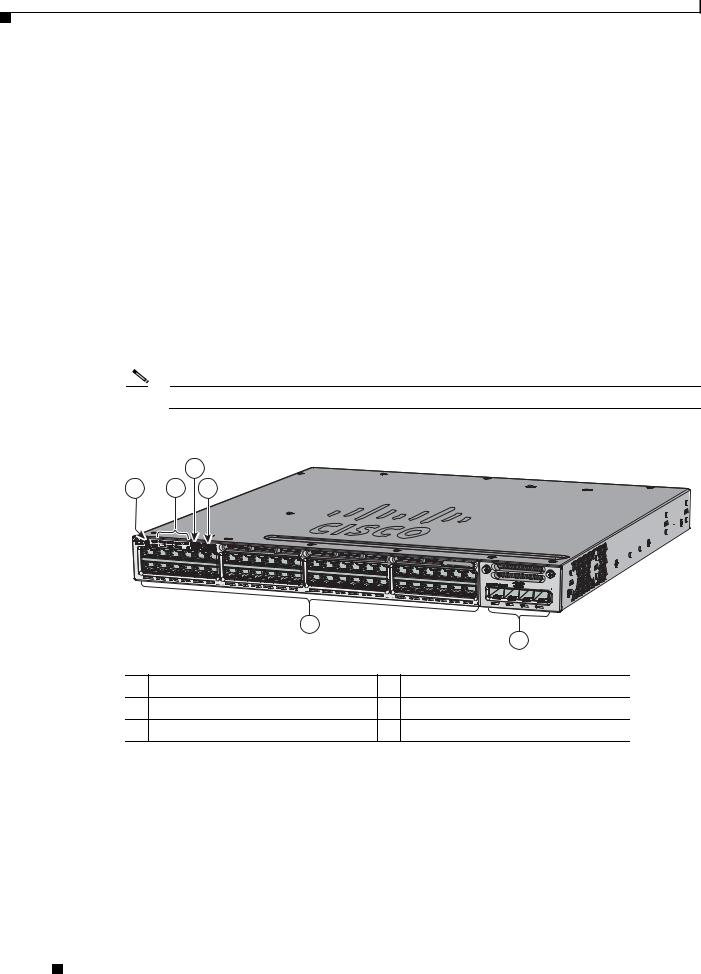
Figure 1-1 Catalyst 3850-48P-L Switch Front Panel
|
|
4 |
|
|
|
1 |
2 |
3 |
|
|
|
|
ACTV |
|
|
|
|
|
|
|
|
|
Catalyst 3850 48 PoE+ |
|
01X |
|
|
|
|
|
|
12X |
13X |
|
C3850- |
|
|
|
24X |
25X |
|
|
|
|
NM-4-1G |
||
|
|
|
|
36X |
37X |
|
|
|
|
|
48X |
|
|
|
|
5 |
|
|
|
|
|
|
6 |
1 |
Mode button |
4 |
USB mini-Type B (console) port |
||
2 |
Status LEDs |
|
5 |
10/100/1000 PoE+ Ethernet ports |
|
3 USB Type A storage port |
6 |
Network module |
|||
344175
Catalyst 3850 Switch Hardware Installation Guide
1-4 |
OL-26779-02 |
|
|
Chapter 1 Product Overview
Front Panel
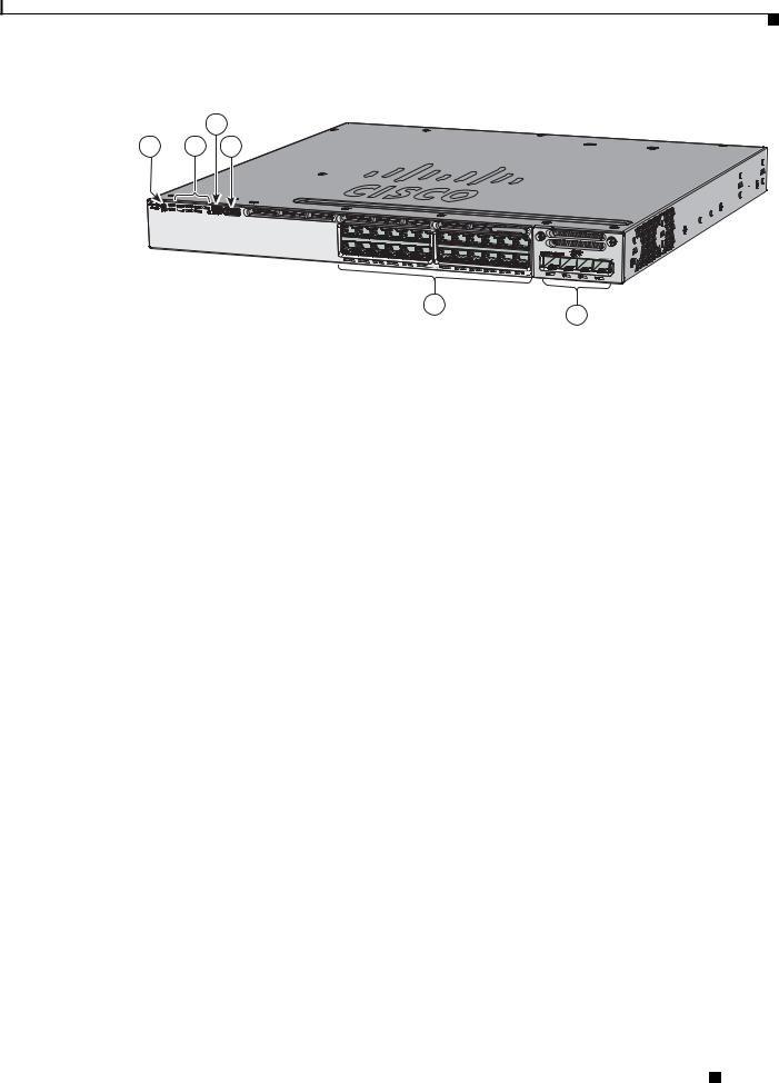
Figure 1-2 Catalyst 3850-24P-L Switch Front Panel
4
1 2 3
ACTV
Catalyst 3850 PoE+


 C3850-NM-4-1G 01X

13X 24X
5
6
344514
1 |
Mode button |
4 |
USB mini-Type B (console) port |
|
|
|
|
2 |
Status LEDs |
5 |
10/100/1000 PoE+ Ethernet ports |
|
|
|
|
3 |
USB Type A storage port |
6 |
Network module |
|
|
|
|
10/100/1000 Ethernet Ports
The 10/100/1000 Ethernet ports use RJ-45 connectors with Ethernet pinouts. The maximum cable length is 328 feet (100 meters). The 100BASE-TX and 1000BASE-T traffic requires Category 5, Category 5e, or Category 6 unshielded twisted pair (UTP) cable. The 10BASE-T traffic can use Category 3 or Category 4 UTP cable.
For information about the 10/100/1000 Ethernet port connections and specifications, see the “10/100/1000 Ethernet Port Connections” section on page 2-19 and Appendix B, “Connector and Cable Specifications.”
PoE, PoE+, and Cisco UPOE Ports
The PoE+ and Cisco Universal Power Over Ethernet (Cisco UPOE) ports use the same connectors as described in the “10/100/1000 Ethernet Ports” section on page 1-5.
They provide:
•PoE+ ports: Support for IEEE 802.3af-compliant powered devices (up to 15.4 W PoE per port) and support for IEEE 802.3at-compliant powered devices (up to 30 W PoE+ per port). The maximum total PoE power in a 1RU switch is 1800 W.
•Cisco UPOE ports: Support for powered devices on all four Ethernet signal pairs (up to 60 W Cisco UPOE per port).
•Support for Cisco-enhanced PoE.
•Support for prestandard Cisco powered devices.
•Configuration for StackPower. When the switch internal power supply module(s) cannot support the total load, StackPower configurations allow the switch to leverage power available from other switches.
•Configurable support for Cisco intelligent power management, including enhanced power negotiation, power reservation, and per-port power policing.
Catalyst 3850 Switch Hardware Installation Guide
|
OL-26779-02 |
1-5 |
|
|
|

Chapter 1 Product Overview
Front Panel
Depending on the installed power supply modules, each port can deliver up to 60 W of Cisco UPOE. See Table 1-15 on page 1-19 for the power supply matrix that defines the available PoE, PoE+, and Cisco UPOE power per port. The output of the PoE+ circuit has been evaluated as a Limited Power Source (LPS) per IEC 60950-1.
Note For information about power supply modules, PoE+ port connections, and PoE+ specifications, see the “Power Supply Modules” section on page 1-18, the “PoE+ and Cisco UPOE Port Connections” section on page 2-20, and Appendix B, “Connector and Cable Specifications.”
Management Ports
•Ethernet management port (see the “Ethernet Management Port” section on page 1-23)
•RJ-45 console port (EIA/TIA-232) (see the “RJ-45 Console Port” section on page 1-23)
•USB mini-Type B console port (5-pin connector)
You can connect the switch to a host such as a Windows workstation or a terminal server through the Ethernet management port, the RJ-45 console port, or the USB console port (USB mini-Type B port).
The USB console port connection uses a USB Type A to 5-pin mini-Type B cable. The USB console interface speeds are the same as the RJ-45 console interface speeds.
USB Mini-Type B Port
The switch provides a USB mini-Type B console connection on the front panel, and the RJ-45 console port on the switch rear panel. Console output is always active on both connectors, but console input is active on only one connector at a time, with the USB connector taking precedence over the RJ-45 connector.
Use a USB type-A-to-USB 5-pin mini-Type B cable to connect a PC or other device to the switch. The required USB cable is included in the optional accessory kit.
The connected device must include a terminal emulation application.
Windows PCs need a driver for the USB port. See the “Installing the Cisco Microsoft Windows USB Device Driver” section on page C-4 for installation instructions.
When the switch detects a valid USB connection to a powered device, input from the RJ-45 console port is immediately disabled, and input from the USB console is enabled. Removing the USB connection immediately reenables input from the Ethernet connection. An LED on the switch front panel (see Figure 1-4) is green when the USB console connection is enabled.
The switch provides a configurable inactivity timeout that reactivates the RJ-45 console if no input activity has occurred on the USB console for a specified time period. After the USB console has been deactivated due to a timeout, you can restore its operation by disconnecting and reconnecting the USB cable. You can disable USB console operation by using Cisco IOS commands. See the switch software configuration guide for details.
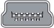
Note The 4-pin mini-Type B connectors resemble 5-pin mini-Type B connectors. They are not compatible. Use only the 5-pin mini-Type B. See Figure 1-3.
Catalyst 3850 Switch Hardware Installation Guide
1-6 |
OL-26779-02 |
|
|

Chapter 1 Product Overview
Front Panel
Figure 1-3 USB Mini-Type B Port
 253163
You can use the command-line interface (CLI) to configure an inactivity timeout which reactivates the RJ-45 console if the USB console has been activated and no input activity has occurred on the USB console for a specified time period.
After the USB console deactivates due to inactivity, you cannot use the CLI to reactivate it. Disconnect and reconnect the USB cable to reactivate the USB console. For information on using the CLI to configure the USB console interface, see the switch software guide.
USB Type A Port
The USB Type A interface provides access to external USB flash devices (also known as thumb drives or USB keys).
The interface supports Cisco USB flash drives with capacities from 64 MB to 1 GB.
Cisco IOS software provides standard file system access to the flash device: read, write, erase, and copy, as well as the ability to format the flash device with a FAT file system.
For more information about the switch management ports, see the switch software configuration guide and the command reference on Cisco.com and the “Connector Specifications” section on page B-1.
Network Modules
The switch supports one hot-swappable network module that provides uplink ports to connect to other devices. The switch should only be operated with either a network module or a blank module installed.
The switch generates logs when you insert or remove a network module with SFP ports.
Catalyst 3850 Switch Hardware Installation Guide
|
OL-26779-02 |
1-7 |
|
|
|

Chapter 1 Product Overview
Front Panel
Table 1-2 Network Modules
Network Module1 |
Description |
C3850-NM-4-1G This module has four 1-Gigabit SFP module slots. Any combination of standard SFP modules are supported. SFP+ modules are not supported.
If you insert an SFP+ module in the 1-Gigabit network module, the SFP+ module does not operate, and the switch logs an error message.
See Figure 3-1 on page 3-2.
C3850-NM-2-10G This module has four slots that support the following combinations:
•Two slots (left side) support only 1-Gigabit SFP modules and two slots (right side) support either 1-Gigabit SFP or 10-Gigabit SFP modules.
•Three slots (left side) support 1-Gigabit SFP modules and one slot (right side) supports 10-Gigabit Ethernet SFP+.
Supported combinations of SFP and SFP+ modules:
•Slots 1, 2, 3, and 4 populated with 1-Gigabit SFP modules.
•Slots 1 and 2 populated with 1-Gigabit SFP modules and Slot 4 populated with one 10-Gigabit SFP+ module.
•Slot 3 and Slot 4 each populated with 10-Gigabit SFP+ modules.
See Figure 3-2 on page 3-2.
C3850-NM-4-10G This module has four 10-Gigabit slots or four 1-Gigabit slots.
Note This is only supported on the 48-port models.
See Figure 3-3 on page 3-3.
C3850-NM-BLANK This module has no uplink ports.
1. All network modules are hot-swappable.
For information about the network modules, see the “Installing a Network Module in the Switch” section on page 2-19. For cable specifications, see Appendix B, “Connector and Cable Specifications.”
SFP and SFP+ Modules
The SFP and SFP+ modules provide copper or fiber-optic connections to other devices. These transceiver modules are field-replaceable, and they provide the uplink interfaces when installed in an SFP module slot. The SFP modules have LC connectors for fiber-optic connections or RJ-45 connectors for copper connections.
Use only Cisco SFP and SFP+ modules on the switch. For the latest information about supported SFP and SFP+ modules, refer to the Cisco Transceiver Modules Compatibility Information at:
http://www.cisco.com/en/US/products/hw/modules/ps5455/products_device_support_tables_list.html
For information about SFP modules, see the SFP module documentation and the “Installing SFP and SFP+ Modules” section on page 3-9. For cable specifications, see Appendix B, “Connector and Cable Specifications.”
The Catalyst 3850 switch supports the SFP module patch cable (CAB-SFP-50CM), a 0.5-meter, copper, passive cable with SFP module connectors at each end. This cable is only used with 1-Gigabit Ethernet SFP ports to connect two Catalyst 3850 switches in a cascaded configuration.
Catalyst 3850 Switch Hardware Installation Guide
1-8 |
OL-26779-02 |
|
|

Chapter 1 Product Overview
Front Panel
LEDs
You can use the switch LEDs to monitor switch activity and its performance. Figure 1-4 shows the switch LEDs and the Mode button that you use to select a port mode.
Figure 1-4 Switch Front Panel LEDs
1 |
2 |
3 |
4 |
5 |
6 |
|
|
||||
|
|
|
01X
7 8 9 10
344176
1 |
STAT (status) |
6 |
CONSOLE (USB mini-Type B (console) port |
2 |
DUPLX (duplex) |
7 |
SYST (system) |
3 |
SPEED |
8 |
ACTV (active) |
4 |
STACK |
9 |
XPS1 (Expandable power system) |
5 |
PoE2 |
10 |
S-PWR (StackPower) |
1.The XPS 2200 is not supported in this release.
2.Only switches with PoE+ ports.
Note The Catalyst 3850 switches might have slight cosmetic differences on the bezels.
Catalyst 3850 Switch Hardware Installation Guide
|
OL-26779-02 |
1-9 |
|
|
|

Chapter 1 Product Overview
Front Panel
SYST LED
Table 1-3 |
SYST LED |
|
|
|
|
|
|
Color |
|
System Status |
|
|
|
|
|
Off |
|
System is not powered on. |
|
|
|
|
|
Green |
|
System is operating normally. |
|
|
|
|
|
Blinking Green |
|
Switch is running POST. |
|
|
|
||
Blinking Amber |
There is a fault with one of the following: |
||
|
|
• Network module (non-traffic-related) |
|
|
|
• |
Power supply |
|
|
• |
Fan module |
|
|
|
|
Amber |
|
System is receiving power but is not functioning |
|
|
|
properly. |
|
|
|
|
|
For information on the SYST LED colors during POST, see the “Diagnosing Problems” section on page 6-1.
XPS LED
Note |
The XPS 2200 is not supported in this release. |
||
|
|
|
|
|
Table 1-4 |
XPS LED |
|
|
|
|
|
|
Color |
|
XPS Status |
|
|
|
|
|
Off |
|
XPS cable is not installed. |
|
|
|
Switch is in StackPower mode. |
|
|
|
|
|
Green |
|
XPS is connected and ready to provide back-up power. |
|
|
|
|
|
Blinking green |
|
XPS is connected but is unavailable because it is providing power to another device |
|
|
|
(redundancy has been allocated to a neighboring device). |
|
|
|
|
|
Amber |
|
The XPS is in standby mode or in a fault condition. See the XPS 2200 |
|
|
|
documentation for information about the standby mode and fault conditions. |
|
|
|
|
|
Blinking amber |
|
The power supply in a switch has failed, and the XPS is providing power to that |
|
|
|
switch (redundancy has been allocated to this device). |
|
|
|
|
For information about the XPS 2200, see the Cisco eXpandable Power System 2200 Hardware Installation Guide on Cisco.com:
http://www.cisco.com/go/xps2200_hw
|
Catalyst 3850 Switch Hardware Installation Guide |
1-10 |
OL-26779-02 |
Chapter 1 Product Overview
Front Panel
Port LEDs and Modes
Each Ethernet port, 1-Gigabit Ethernet module slot, and 10-Gigabit Ethernet module slot has a port LED. These port LEDs, as a group or individually, display information about the switch and about the individual ports. The port mode determines the type of information shown by the port LEDs. Table 1-5 lists the mode LEDs and their associated port modes and meanings.
To select or change a mode, press the Mode button until the desired mode is highlighted. When you change port modes, the meanings of the port LED colors also change. Table 1-6 explains how to interpret the port LED colors in different port modes.
When you press the Mode button on any switch in the switch stack, all the stack switches change to show the same selected mode. For example, if you press the Mode button on the active switch to show the SPEED LED, all the other switches in the stack also show the SPEED LED.
Table 1-5 |
Port Mode LEDs |
|
|
|
|||
|
|
|
|
|
|
|
|
Mode LED |
|
Port Mode |
|
Description |
|||
|
|
|
|
|
|
|
|
STAT |
|
Port status |
|
The port status. This is the default mode. |
|||
|
|
|
|
|
|
|
|
SPEED |
|
Port speed |
|
The port operating speed: 10, 100, or 1000 Mb/s. |
|||
|
|
|
|
|
|
|
|
DUPLX |
|
Port duplex mode |
|
The port duplex mode: full duplex or half duplex. |
|||
|
|
|
|
|
|
|
|
ACTV |
|
Active |
|
The active switch status. |
|||
|
|
|
|
|
|
|
|
STACK |
|
Stack member status |
|
The stack member status. |
|||
|
|
StackWise port status |
|
The StackWise port status. See the “STACK LED” section on |
|||
|
|
|
|
|
|
page 1-14. |
|
|
|
|
|
|
|
|
|
PoE1 |
|
PoE+ port power |
|
The PoE+ port status. |
|||
1. Only switches with PoE+ ports. |
|
|
|
||||
Table 1-6 |
Meaning of Switch LED Colors in Different Modes |
||||||
|
|
|
|
|
|
||
Port Mode |
|
Port LED Color |
|
Meaning |
|||
|
|
|
|
|
|
||
STAT |
|
Off |
|
No link, or port was administratively shut down. |
|||
(port status) |
|
|
|
|
|
|
|
|
Green |
|
Link present, no activity. |
||||
|
|
|
|
||||
|
|
|
|
|
|
|
|
|
|
|
Blinking green |
|
Activity. Port is sending or receiving data. |
||
|
|
|
|
|
|
|
|
|
|
|
Alternating |
|
Link fault. Error frames can affect connectivity, and errors such as |
||
|
|
|
green-amber |
|
excessive collisions, CRC errors, and alignment and jabber errors |
||
|
|
|
|
|
are monitored for a link-fault indication. |
||
|
|
|
|
|
|
|
|
|
|
|
Amber |
|
Port is blocked by Spanning Tree Protocol (STP) and is not |
||
|
|
|
|
|
forwarding data. |
||
|
|
|
|
|
After a port is reconfigured, the port LED can be amber for up to 30 |
||
|
|
|
|
|
seconds as STP checks the switch for possible loops. |
||
|
|
|
|
|
|
|
|
|
|
Catalyst 3850 Switch Hardware Installation Guide |
|
|
|
|
|
|
|||
|
OL-26779-02 |
|
|
1-11 |
|
|
|
|
|
||

Chapter 1 Product Overview
Front Panel
Table 1-6 Meaning of Switch LED Colors in Different Modes (continued)
Port Mode |
Port LED Color |
Meaning |
|
|
|
|
|
SPEED |
10/100/1000/SFP ports |
||
|
|
|
|
|
Off |
Port is operating at 10 Mb/s. |
|
|
|
|
|
|
Green |
Port is operating at 100 Mb/s. |
|
|
|
|
|
|
Single green |
Port is operating at 1000 Mb/s. |
|
|
flash (on for |
|
|
|
100 ms, off for |
|
|
|
1900 ms) |
|
|
|
|
|
|
|
Network module slots |
||
|
|
|
|
|
Off |
Port is not operating. |
|
|
|
|
|
|
Blinking green |
Port is operating at up to 10 Gb/s. |
|
|
|
|
|
DUPLX |
Off |
Port is operating in half duplex. |
|
(duplex) |
|
|
|
Green |
Port is operating in full duplex. |
||
|
|||
|
|
|
|
ACTV |
Off |
The switch is not the active switch. |
|
(data active |
|
Note For a standalone switch, this LED is off. |
|
switch) |
|
||
|
|
||
Green |
The switch is the active switch. |
||
|
|||
|
|
|
|
|
Amber |
Error during active switch election. |
|
|
|
|
|
|
Blinking green |
Switch is a standby member of a data stack and assumes active |
|
|
|
responsibilities if the current active switch fails. |
|
|
|
|
|
STACK |
Off |
No stack member corresponding to that member number. |
|
(stack member) |
|
|
|
Blinking green |
Stack member number. |
||
|
|
|
|
|
Green |
Member numbers of other stack member switches. |
|
|
|
|
|
|
Catalyst 3850 Switch Hardware Installation Guide |
1-12 |
OL-26779-02 |

Chapter 1 Product Overview
Front Panel
Table 1-6 |
Meaning of Switch LED Colors in Different Modes (continued) |
|
|||||
|
|
|
|
|
|||
Port Mode |
|
Port LED Color |
Meaning |
|
|||
|
|
|
|
|
|||
PoE+1 |
|
Off |
PoE+ is off. |
|
|||
|
|
|
If the powered device is receiving power from an AC power source, |
|
|||
|
|
|
the port LED is off even if the device is connected to the switch port. |
|
|||
|
|
|
|
|
|||
|
|
Green |
PoE+ is on. The port LED is green when the switch port is providing |
|
|||
|
|
|
power. |
|
|||
|
|
|
|
|
|||
|
|
Alternating |
PoE+ is denied because providing power to the powered device will |
|
|||
|
|
green and |
exceed the switch power capacity. |
|
|||
|
|
amber |
|
|
|
|
|
|
|
|
|
|
|||
|
|
Blinking amber |
PoE+ is off due to a fault or because it has exceeded a limit set in |
|
|||
|
|
|
the switch software. |
|
|||
|
|
|
|
|
|
|
|
|
|
|
Caution PoE+ faults occur when noncompliant cabling or |
|
|||
|
|
|
|
|
|
powered devices are connected to a PoE+ port. Use only |
|
|
|
|
|
|
|
standard-compliant cabling to connect Cisco prestandard |
|
|
|
|
|
|
|
IP Phones and wireless access points or |
|
|
|
|
|
|
|
IEEE 802.3af-compliant devices to PoE+ ports. You |
|
|
|
|
|
|
|
must remove from the network any cable or device that |
|
|
|
|
|
|
|
causes a PoE+ fault. |
|
|
|
|
|
|
|
||
|
|
|
|
|
|||
|
|
Amber |
PoE+ for the port has been disabled. |
|
|||
|
|
|
Note PoE+ is enabled by default. |
|
|||
|
|
|
|
|
|
|
|
1. Only switches with PoE or PoE+ ports.
USB Console LED
The USB console LED (Figure 1-4) shows whether there is an active USB connection to the port.
Table 1-7 |
USB Console Port LED |
|
|
|
|
Color |
|
Description |
|
|
|
Off |
|
USB console is disabled. |
|
|
|
Green |
|
USB console is enabled. |
|
|
|
S-PWR LED
Table 1-8 |
S-PWR LED |
|
|
|
|
Color |
|
Description |
|
|
|
Off |
|
StackPower cable is not connected, or the switch is in standalone |
|
|
mode. |
|
|
|
Green |
|
Each StackPower port is connected to another switch. |
|
|
|
|
|
Catalyst 3850 Switch Hardware Installation Guide |
|
|
|
|
|
|
|||
|
OL-26779-02 |
|
|
1-13 |
|
|
|
|
|
||

Chapter 1 Product Overview
Front Panel
Table 1-8 |
S-PWR LED |
|
|
|
|
Color |
|
Description |
|
|
|
Blinking Green |
|
This appears on the switch in a StackPower ring configuration |
|
|
that detects an open ring or has only one StackPower cable |
|
|
connected. |
|
|
|
Amber |
|
There is a fault: load shedding is occurring, a StackPower cable |
|
|
is defective, or administrative action is required. See the switch |
|
|
software configuration guide for information about configuring |
|
|
StackPower. |
|
|
|
Blinking Amber |
The StackPower budget is not sufficient to meet current power |
|
|
|
demands. |
|
|
|
ACTV LED
Table 1-9 |
ACTV LED |
|
|
|
|
Color |
|
Description |
|
|
|
Off |
|
Switch is not the active switch. |
|
|
|
Green |
|
Switch is the active switch or a standalone switch. |
|
|
|
Amber |
|
An error occurred when the switch was selecting the active |
|
|
switch, or another type of stack error occurred. |
|
|
|
Slow blinking green |
Switch is in stack standby mode. |
|
|
|
|
STACK LED
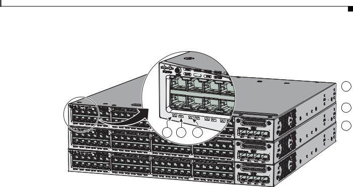
The STACK LED shows the sequence of member switches in a stack. Up to four switches can be members of a stack. The first four port LEDs show the member number of a switch in a stack. Figure 1-5 shows the LEDs on the first switch, which is stack member number 1. For example, if you press the Mode button and select Stack, the LED for port 1 blinks green. The LEDs for ports 2 and 3 are solid green, as these represent the member numbers of other switches in the stack. The other port LEDs are off because there are no more members in the stack.
|
Catalyst 3850 Switch Hardware Installation Guide |
1-14 |
OL-26779-02 |
Chapter 1 Product Overview
Front Panel
Figure 1-5 |
STACK LED |
ACTV
ACTV |
|
|
|
|
|
|
|
|
|
01X |
|
|
|
01X |
|
|
|
|
|
|
12X |
13X |
|
|
|
|
|
|
24X |
25X |
4 |
5 |
6 |
C3850-NM-4-1G |
|
|
|
48X |
|||
|
|
|
|
|
|
|
|
|
|
|
|
|
Catalyst 3850 48 PoE+ |
01X |
|
|
|
|
|
|
12X |
13X |
|
|
|
|
|
|
24X |
25X |
|
|
|
C3850-NM-4-1G |
|
|
|
|
36X |
37X |
|
|
|
|
|
|
|
48X |
|
|
|
|
|
|
Catalyst 3850 48 PoE+ |
01X |
|
|
|
|
|
|
12X |
13X |
|
|
|
|
|
|
24X |
25X |
|
|
|
C3850-NM-4-1G |
|
|
|
|
36X |
37X |
|
|
|
|
|
|
|
48X |
 1
1
 2
2
 3
3
344178
1 |
Stack member 1 |
4 |
LED blinks green to show that this is switch 1 in the stack. |
|
|
|
|
2 |
Stack member 2 |
5 |
LED is solid green to show that switch 2 is a stack member. |
|
|
|
|
3 |
Stack member 3 |
6 |
LED is solid green to show that switch 3 is a stack member. |
|
|
|
|
When you select the STACK LED mode, the representative STACK LEDs are green when the StackWise ports are up, and the representative STACK LEDs are amber when the ports are down.
PoE LED
The PoE LED indicates the status of the PoE mode: either PoE, PoE+, or Cisco UPOE.
Table 1-10 |
PoE LED Status |
|
|
|
|
Color |
|
Status of PoE mode (PoE, PoE+, or Cisco UPOE) |
|
|
|
Off |
|
PoE mode is not selected. None of the 10/100/1000 ports have been denied power |
|
|
or are in a fault condition. |
|
|
|
Green |
|
PoE mode is selected, and the port LEDs show the PoE mode status. |
|
|
|
Blinking amber |
|
PoE mode is not selected. At least one of the 10/100/1000 ports has been denied |
|
|
power, or at least one of the 10/100/1000 ports has a PoE mode fault. |
|
|
|
|
|
Catalyst 3850 Switch Hardware Installation Guide |
|
|
|
|
|
|
|||
|
OL-26779-02 |
|
|
1-15 |
|
|
|
|
|
||
Chapter 1 Product Overview
Front Panel
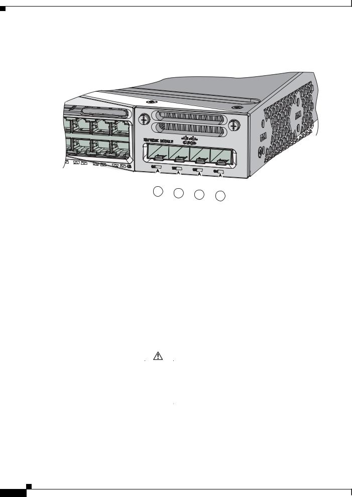
Network Module LEDs
Figure 1-6 Network Module LEDs
Catalyst 3850 |
48 PoE+ |
|
C3850-NM -
-
 4
4
 -
- 1G
1G

344177
|
|
|
|
|
|
|
|
|
|
|
|
|
|
|
|
|
|
|
|
|
|
|
|
|
|
|
|
|
|
|
|
|
|
|
|
1 |
2 |
3 |
4 |
|
|
|||||||||
|
|
|
|
|
|
|
|
|
||||||||
|
|
|
|
|
|
|
|
|
|
|
|
|
|
|
||
1 |
G1 LED |
|
|
|
3 |
|
|
G3 LED |
|
|
|
|
|
|
||
|
|
|
|
|
|
|
|
|
|
|
|
|
|
|
||
2 |
G2 LED |
|
|
|
4 |
|
|
G4 LED |
|
|
|
|
|
|
||
|
|
|
|
|
|
|
|
|
|
|
|
|
|
|||
Table 1-11 |
Network Module LEDs |
|
|
|
|
|
|
|||||||||
|
|
|
|
|
|
|
|
|
||||||||
Color |
|
Network Module Link Status |
|
|
||||||||||||
|
|
|
|
|
|
|
|
|
|
|
|
|||||
Off |
|
|
Link is off. |
|
|
|
|
|
|
|||||||
|
|
|
|
|
|
|
|
|
|
|||||||
Green |
|
Link is on; no activity. |
|
|
|
|
||||||||||
|
|
|
|
|
|
|
|
|
||||||||
Blinking green |
|
Activity on a link; no faults. |
|
|
||||||||||||
|
|
|
Note The LED will blink green even when there is very little |
|
|
|||||||||||
|
|
|
|
|
|
|
|
control traffic. |
|
|
|
|
||||
|
|
|
|
|
|
|
|
|
||||||||
Blinking amber |
|
Link is off due to a fault or because it has exceeded a limit set in the |
|
|
||||||||||||
|
|
|
switch software. |
|
|
|
|
|
|
|||||||
|
|
|
|
|
|
|
|
|
|
|
|
|
|
|
||
|
|
|
Caution Link faults occur when noncompliant cabling is |
|
|
|||||||||||
|
|
|
|
|
|
|
|
|
connected to an SFP or SFP+ port. Use only |
|
|
|||||
|
|
|
|
|
|
|
|
|
standard-compliant cabling to connect to Cisco SFP and |
|
|
|||||
|
|
|
|
|
|
|
|
|
SFP+ ports. You must remove from the network any cable |
|
|
|||||
|
|
|
|
|
|
|
|
|
or device that causes a link fault. |
|
|
|||||
|
|
|
|
|
|
|
|
|
|
|
|
|
||||
|
|
|
|
|
|
|
|
|
||||||||
Amber |
|
Link for the SFP or SFP+ has been disabled. |
|
|
||||||||||||
|
|
|
|
|
|
|
|
|
|
|
|
|
|
|
|
|
|
Catalyst 3850 Switch Hardware Installation Guide |
1-16 |
OL-26779-02 |
Chapter 1 Product Overview
Rear Panel
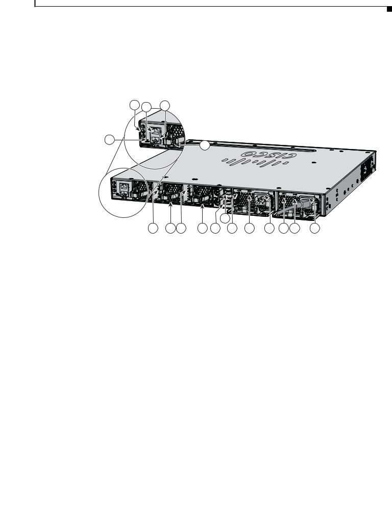
Rear Panel
The switch rear panel includes StackWise connectors, StackPower connectors, ports, fan modules, and power supply modules. See Figure 1-7.
Figure 1-7 Catalyst 3850 Switch Rear Panel
1 2 3
4
MGMT
CONSOLE |
MGMT |
6 5 6
5
344179
PWR-C1-715WAC
PWR-C1-715WAC
|
|
8 |
|
|
|
|
|
5 |
7 |
9 |
10 |
11 |
9 |
10 |
11 |
1 |
Ground connector |
7 |
StackPower connector |
|
|
|
|
2 |
CONSOLE (RJ-45 console port) |
8 |
StackPower connector |
|
|
|
|
3 |
MGMT (RJ-45 10/100/1000 management |
9 |
AC OK (input) status LED |
|
port) |
|
|
|
|
|
|
4 |
RESET button |
10 |
PS OK (output) status LED |
|
|
|
|
5 |
Fan module |
11 |
Power supply modules (AC power supply |
|
|
|
modules shown) |
|
|
|
|
6 |
StackWise port connector |
|
|
|
|
|
|
RJ-45 Console Port LED
Table 1-12 |
RJ-45 Console Port LED |
|
|
|
|
Color |
|
RJ-45 Console Port Status |
|
|
|
Off |
|
RJ-45 console is disabled. USB console is active. |
|
|
|
Green |
|
RJ-45 console is enabled. USB console is disabled. |
|
|
|
|
|
Catalyst 3850 Switch Hardware Installation Guide |
|
|
|
|
|
|
|||
|
OL-26779-02 |
|
|
1-17 |
|
|
|
|
|
||

Chapter 1 Product Overview
Rear Panel
StackWise Ports
StackWise ports are used to connect switches in StackWise stacking configurations. The Catalyst 3850 switch ships with a 0.5-meter StackWise cable that you can use to connect the StackWise ports. For more information on StackWise cables, see StackWise Cables, page B-5.
Caution Use only approved cables, and connect only to similar Cisco equipment. Equipment might be damaged if connected to nonapproved Cisco cables or equipment.
Power Supply Modules
The 24and 48-port switches are powered through one or two internal power supply modules.
Supported power supply modules:
•PWR-C1-350WAC
•PWR-C1-715WAC
•PWR-C1-1100WAC
•PWR-C1-440WDC
The switch has two internal power supply module slots. You can use two AC modules, two DC modules, a mixed configuration of one AC and one DC power supply module, or one power supply module and a blank module.
The switch can operate with either one or two active power supply modules or with power supplied by a stack. A Catalyst 3850 switch that is in a StackPower stack can operate with power supplied by other switches in the stack.
Table 1-1 show the default power supply modules that ship with each switch model. All power supply modules (except the blank modules) have internal fans. All switches ship with a blank power supply module in the second power supply slot.
Caution Do not operate the switch with one power supply module slot empty. For proper chassis cooling, both power supply module slots must be populated with either a power supply or a blank module.
The 350-W and 715-W AC power supply modules are autoranging units that support input voltages between 100 and 240 VAC. The 1100-W power supply module is an autoranging unit that supports input voltages between 115 and 240 VAC. The 440-W DC power supply module has dual input feeds (A and B) and supports input voltages between 36 and 72 VDC. The output voltage range is 51–57 V.
Each AC power supply module has a power cord for connection to an AC power outlet. The 1100-W and 715-W modules use a 16-AWG cord (only North America). All other modules use an 18-AWG cord. The DC-power supply module must be wired to a DC-power source.
Table 1-13, Table 1-14, and Table 1-15 shows the PoE available and PoE requirements for Catalyst 3850 switches.
|
Catalyst 3850 Switch Hardware Installation Guide |
1-18 |
OL-26779-02 |

Chapter 1 Product Overview
Rear Panel
Table 1-13 |
Available PoE with AC Power Supply |
|
|
|
|
|
|||
|
|
|
|
|
|
|
|
|
|
Models |
|
|
|
Default Power Supply |
|
Available PoE |
|||
|
|
|
|
|
|
|
|
|
|
24-port data switch |
|
|
PWR-C1-350WAC |
|
— |
||||
|
|
|
|
|
|
|
|
|
|
48-port data switch |
|
|
|
|
|
|
|
|
|
|
|
|
|
|
|
|
|
|
|
24-port PoE switch |
|
|
PWR-C1-715WAC |
|
435 W |
||||
|
|
|
|
|
|
|
|
|
|
48-port PoE+ switch |
|
|
|
|
|
|
|
|
|
|
|
|
|
|
|
|
|
|
|
48-port full PoE+ switch |
|
|
PWR-C1-1100WAC |
|
800 W |
||||
|
|
|
|
|
|
|
|
|
|
24-port Cisco UPOE |
|
|
PWR-C1-1100WAC |
|
800 W |
||||
switch |
|
|
|
|
|
|
|
|
|
|
|
|
|
|
|
|
|
|
|
48-port Cisco UPOE |
|
|
|
|
|
|
|
|
|
switch |
|
|
|
|
|
|
|
|
|
|
|
|
|
|
|
|
|
|
|
Table 1-14 |
Available PoE with DC Power Supply |
|
|
|
|
|
|||
|
|
|
|
|
|
|
|
|
|
|
|
|
|
Number of Power |
|
|
|
|
|
Models |
|
|
|
Supplies |
|
Available PoE |
|||
|
|
|
|
|
|
||||
24-port PoE+ switch |
|
1 |
220 W |
||||||
|
|
|
|
|
|
|
|
||
|
|
|
2 |
|
660 W |
||||
|
|
|
|
|
|
||||
48-port PoE+ switch |
|
1 |
185 W |
||||||
|
|
|
|
|
|
|
|
||
|
|
|
2 |
|
625 W |
||||
|
|
|
|
|
|
|
|||
24-port Cisco UPOE |
|
1 |
|
220 W |
|||||
switch |
|
|
|
|
|
|
|
|
|
|
|
2 |
|
660 W |
|||||
|
|
|
|
||||||
|
|
|
|
|
|
|
|||
48-port Cisco UPOE |
|
1 |
|
185 W |
|||||
switch |
|
|
|
|
|
|
|
|
|
|
|
2 |
|
625 W |
|||||
|
|
|
|
||||||
|
|
|
|
|
|
|
|||
Table 1-15 |
Switch Power Supply Requirements for PoE, PoE+, and Cisco UPOE |
||||||||
|
|
|
|
|
|
||||
PoE Option |
|
24-Port Switch |
|
|
48-Port Switch1 |
||||
PoE (up to 15.4 per |
(1) 715-W |
|
|
These are the combinations of power |
|||||
port) |
|
|
|
|
|
|
supplies: |
||
|
|
|
|
|
|
|
• (1) 1100-W |
||
|
|
|
|
|
|
|
• (1) 715-W + (1) 715-W |
||
|
|
|
|
|
|
|
|
|
|
|
|
Catalyst 3850 Switch Hardware Installation Guide |
|
|
|
|
|
|
|||
|
OL-26779-02 |
|
|
1-19 |
|
|
|
|
|
||

Chapter 1 Product Overview
Rear Panel
Table 1-15 |
Switch Power Supply Requirements for PoE, PoE+, and Cisco UPOE (continued) |
|||
|
|
|
|
|
PoE Option |
|
24-Port Switch |
48-Port Switch1 |
|
PoE+ (up to 30 W per |
These are the combinations of |
These are the combinations of power |
||
ports |
|
power supplies: |
supplies: |
|
|
|
• |
(1) 1100-W |
• (1) 1100-W + (1) 715-W |
|
|
• |
(1) 715-W 715-W |
• (2) 1100-W |
|
|
|
||
Cisco UPOE (up to 60 |
(2) 1100-W |
These are the combinations of power |
||
W per port) |
|
|
|
supplies: |
|
|
|
|
(1) 1100-W + (1) 715-W |
|
|
|
|
(2) 1100-W |
|
|
|
|
Note Up to 30 PoE ports can receive |
|
|
|
|
full Cisco UPOE. |
|
|
|
|
|
1. A 48-port switch with one 715-W power supply provides up to 8.7 W of PoE to all ports.
|
Catalyst 3850 Switch Hardware Installation Guide |
1-20 |
OL-26779-02 |
Loading...