


 Loading...
Cisco ATA 187 Analog Telephone Adaptor Administration Guide for SIP
Version 1.0
Americas Headquarters
Cisco Systems, Inc. 170 West Tasman Drive
San Jose, CA 95134-1706 USA http://www.cisco.com Tel: 408 526-4000
800 553-NETS (6387) Fax: 408 527-0883
Text Part Number: OL-21862-01

THE SPECIFICATIONS AND INFORMATION REGARDING THE PRODUCTS IN THIS MANUAL ARE SUBJECT TO CHANGE WITHOUT NOTICE. ALL STATEMENTS, INFORMATION, AND RECOMMENDATIONS IN THIS MANUAL ARE BELIEVED TO BE ACCURATE BUT ARE PRESENTED WITHOUT WARRANTY OF ANY KIND, EXPRESS OR IMPLIED. USERS MUST TAKE FULL RESPONSIBILITY FOR THEIR APPLICATION OF ANY PRODUCTS.
THE SOFTWARE LICENSE AND LIMITED WARRANTY FOR THE ACCOMPANYING PRODUCT ARE SET FORTH IN THE INFORMATION PACKET THAT SHIPPED WITH THE PRODUCT AND ARE INCORPORATED HEREIN BY THIS REFERENCE. IF YOU ARE UNABLE TO LOCATE THE SOFTWARE LICENSE OR LIMITED WARRANTY, CONTACT YOUR CISCO REPRESENTATIVE FOR A COPY.
The following information is for FCC compliance of Class A devices: This equipment has been tested and found to comply with the limits for a Class A digital device, pursuant to part 15 of the FCC rules. These limits are designed to provide reasonable protection against harmful interference when the equipment is operated in a commercial environment. This equipment generates, uses, and can radiate radio-frequency energy and, if not installed and used in accordance with the instruction manual, may cause harmful interference to radio communications. Operation of this equipment in a residential area is likely to cause harmful interference, in which case users will be required to correct the interference at their own expense.
The following information is for FCC compliance of Class B devices: The equipment described in this manual generates and may radiate radio-frequency energy. If it is not installed in accordance with Cisco’s installation instructions, it may cause interference with radio and television reception. This equipment has been tested and found to comply with the limits for a Class B digital device in accordance with the specifications in part 15 of the FCC rules. These specifications are designed to provide reasonable protection against such interference in a residential installation. However, there is no guarantee that interference will not occur in a particular installation.
Modifying the equipment without Cisco’s written authorization may result in the equipment no longer complying with FCC requirements for Class A or Class B digital devices. In that event, your right to use the equipment may be limited by FCC regulations, and you may be required to correct any interference to radio or television communications at your own expense.
You can determine whether your equipment is causing interference by turning it off. If the interference stops, it was probably caused by the Cisco equipment or one of its peripheral devices. If the equipment causes interference to radio or television reception, try to correct the interference by using one or more of the following measures:
•Turn the television or radio antenna until the interference stops.
•Move the equipment to one side or the other of the television or radio, or farther away from the television or radio.
•Plug the equipment into an outlet that is on a different circuit from the television or radio. (That is, make certain the equipment and the television or radio are on circuits controlled by different circuit breakers or fuses.)
Modifications to this product not authorized by Cisco Systems, Inc. could void the FCC approval and negate your authority to operate the product.
The Cisco implementation of TCP header compression is an adaptation of a program developed by the University of California, Berkeley (UCB) as part of UCB’s public domain version of the UNIX operating system. All rights reserved. Copyright © 1981, Regents of the University of California.
NOTWITHSTANDING ANY OTHER WARRANTY HEREIN, ALL DOCUMENT FILES AND SOFTWARE OF THESE SUPPLIERS ARE PROVIDED “AS IS” WITH ALL FAULTS. CISCO AND THE ABOVE-NAMED SUPPLIERS DISCLAIM ALL WARRANTIES, EXPRESSED OR IMPLIED, INCLUDING, WITHOUT LIMITATION, THOSE OF MERCHANTABILITY, FITNESS FOR A PARTICULAR PURPOSE AND NONINFRINGEMENT OR ARISING FROM A COURSE OF DEALING, USAGE, OR TRADE PRACTICE.
IN NO EVENT SHALL CISCO OR ITS SUPPLIERS BE LIABLE FOR ANY INDIRECT, SPECIAL, CONSEQUENTIAL, OR INCIDENTAL DAMAGES, INCLUDING, WITHOUT LIMITATION, LOST PROFITS OR LOSS OR DAMAGE TO DATA ARISING OUT OF THE USE OR INABILITY TO USE THIS MANUAL, EVEN IF CISCO OR ITS SUPPLIERS HAVE BEEN ADVISED OF THE POSSIBILITY OF SUCH DAMAGES.
Cisco and the Cisco Logo are trademarks of Cisco Systems, Inc. and/or its affiliates in the U.S. and other countries. A listing of Cisco's trademarks can be found at www.cisco.com/go/trademarks. Third party trademarks mentioned are the property of their respective owners. The use of the word partner does not imply a partnership relationship between Cisco and any other company. (1005R)
The Java logo is a trademark or registered trademark of Sun Microsystems, Inc. in the U.S. or other countries.
Cisco ATA 187 Analog Telephone Adaptor Administration Guide for SIP
© 2010 Cisco Systems, Inc. All rights reserved.

Contents
C O N T E N T S
Preface vii
Cisco ATA 187 Analog Telephone Adaptor Overview |
1-1 |
|||||
Session Initiation Protocol Overview |
1-2 |
|
|
|||
SIP Capabilities |
1-2 |
|
|
|
|
|
Components of SIP |
1-3 |
|
|
|
|
|
SIP Clients |
1-4 |
|
|
|
|
|
SIP Servers |
1-4 |
|
|
|
|
|
Hardware Overview |
1-5 |
|
|
|
|
|
Software Features |
1-5 |
|
|
|
|
|
Secure Real-Time Transport Protocol |
1-6 |
|
||||
Name Signaling Event based passthrough 1-6 |
|
|||||
Transport Layer Security Protocol |
1-6 |
|
||||
T.38 Fax Relay |
1-6 |
|
|
|
|
|
Voice Codecs Supported |
1-6 |
|
|
|
||
Other Supported Protocols |
1-6 |
|
|
|
||
ATA 187 SIP Services |
1-7 |
|
|
|
||
Modem Standards |
1-7 |
|
|
|
|
|
Fax Services 1-8 |
|
|
|
|
|
|
Methods Supported |
1-8 |
|
|
|
|
|
Supplementary Services |
1-9 |
|
|
|
||
Installation and Configuration Overview |
1-9 |
|
||||
Preparing to Install the ATA 187 on Your Network |
2-1 |
|||||
Understanding Interactions with Other Cisco Unified IP Communications Products 2-1
Understanding How the ATA 187 Interacts with Cisco Unified Communications Manager 2-2
Providing Power to the ATA 187 2-2
Power Guidelines 2-2
Power Outage 2-2
Understanding Phone Configuration Files 2-3
Understanding the ATA 187 Startup Process 2-4
Adding the ATA 187 to the Cisco Unified Communications Manager Database 2-5
Adding the ATA 187 with Auto-Registration 2-6
Adding the ATA 187 with Cisco Unified Communications Manager Administration 2-6
Determining the MAC Address of an ATA 187 2-7
Cisco ATA 187 Analog Telephone Adaptor Administration Guide for SIP (Version 1.0)
|
OL-21862-01 |
iii |
|

Contents
Installing the ATA 187 3-1 |
|
|
|
|
|
Network Requirements |
3-1 |
|
|
|
|
Safety Recommendations |
3-2 |
|
|
|
|
What the ATA 187 Package Includes |
3-2 |
|
|||
Installing the ATA 187 |
3-3 |
|
|
|
|
Attaching a Phone to the ATA 187 |
3-3 |
|
|||
Verifying the ATA 187 Startup Process |
3-3 |
|
|||
Configuring Startup Network Settings |
3-4 |
|
|||
Configuring Security on the ATA 187 |
3-4 |
|
|||
Configuring the ATA 187 |
4-1 |
|
|
|
|
Telephony Features Available for the ATA 187 4-1 |
|
||||
Configuring Product Specific Configuration Parameters |
4-5 |
||||
Adding Users to Cisco Unified Communications Manager |
4-6 |
||||
Configuring Fax Services |
5-1 |
|
|
|
|
Using Fax Mode 5-1 |
|
|
|
|
|
Fax Modem Standards |
5-1 |
|
|
|
|
Fax Modem Speeds |
5-2 |
|
|
|
|
Troubleshooting and Maintenance |
6-1 |
|
|||
Resolving Startup Problems |
6-1 |
|
|
|
|
Symptom: The ATA 187 Does Not Go Through its Normal Startup Process 6-1 |
|||||
Symptom: The ATA 187 Does Not Register with Cisco Unified Communications Manager 6-2 |
|||||
Checking Network Connectivity 6-2 |
|
||||
Verifying TFTP Server Settings |
6-2 |
|
|||
Verifying DNS Settings |
6-3 |
|
|
||
Verifying Cisco Unified Communications Manager Settings 6-3
Cisco Unified Communications Manager and TFTP Services Are Not Running 6-3
Creating a New Configuration File 6-3
Registering the Phone with Cisco Unified Communications Manager 6-4
Symptom: ATA 187 Unable to Obtain IP Address 6-4
ATA 187 Resets Unexpectedly 6-5
Verifying Physical Connection 6-5
Identifying Intermittent Network Outages 6-5
Verifying DHCP Settings 6-5
Cisco ATA 187 Analog Telephone Adaptor Administration Guide for SIP (Version 1.0)
|
iv |
OL-21862-01 |
|
|
|

Contents
Checking Static IP Address Settings |
6-6 |
|
||||||
Verifying Voice VLAN Configuration |
6-6 |
|
||||||
Eliminating DNS or Other Connectivity Errors |
6-6 |
|||||||
Checking Power Connection |
|
6-7 |
|
|
||||
Troubleshooting ATA 187 Security |
6-7 |
|
|
|||||
General Troubleshooting Tips |
6-7 |
|
|
|
||||
Where to Go for More Troubleshooting Information |
6-9 |
|||||||
Cleaning the ATA 187 |
6-10 |
|
|
|
|
|||
Using SIP Supplementary Services |
7-1 |
|
|
|||||
Common Supplementary Services |
7-1 |
|
|
|||||
Attended Transfer |
7-2 |
|
|
|
|
|||
Call Pickup |
7-2 |
|
|
|
|
|
|
|
Caller ID |
7-2 |
|
|
|
|
|
|
|
Call-Waiting Caller ID |
7-2 |
|
|
|
|
|||
Call Hold |
|
7-2 |
|
|
|
|
|
|
Group Call Pickup |
7-3 |
|
|
|
|
|
||
Meet–Me Conference |
7-3 |
|
|
|
||||
Privacy |
7-3 |
|
|
|
|
|
|
|
Shared Line |
7-3 |
|
|
|
|
|
|
|
Speed Dial |
7-4 |
|
|
|
|
|
|
|
Redial |
7-4 |
|
|
|
|
|
|
|
Unattended Transfer |
7-4 |
|
|
|
|
|||
Semi-unattended Transfer |
7-4 |
|
|
|||||
Fully Unattended Transfer |
7-5 |
|
|
|||||
Voice Mail Indication |
7-5 |
|
|
|
|
|||
Voice-Messaging System |
7-5 |
|
|
|||||
Making a Conference Call in the United States |
7-5 |
|||||||
Making a Conference Call in Sweden |
7-6 |
|
||||||
Call Waiting in the United States 7-6 |
|
|||||||
Call Waiting in Sweden |
7-6 |
|
|
|
||||
About Call Forwarding |
7-6 |
|
|
|
||||
Call Forwarding in the United States |
7-7 |
|
||||||
Call Forwarding in Sweden |
7-7 |
|
|
|||||
Voice Menu Codes |
8-1 |
|
|
|
|
|
|
|
Accessing the IVR and Configuring Your Phone Setting 8-1
Cisco ATA 187 Analog Telephone Adaptor Administration Guide for SIP (Version 1.0)
|
OL-21862-01 |
v |
|

Contents
ATA 187 Specifications |
A-1 |
Physical Specifications |
A-1 |
Electrical Specifications |
A-2 |
Environmental Specifications A-2 |
|
Physical Interfaces A-2 |
|
Ringing Characteristics |
A-3 |
Software Specifications |
A-3 |
SIP Compliance Reference Information A-4
Recommended ATA 187 Tone Parameter Values by Country B-1
G L O S S A R Y
I N D E X
Cisco ATA 187 Analog Telephone Adaptor Administration Guide for SIP (Version 1.0)
|
vi |
OL-21862-01 |
|
|
|

Preface
Overview
The Cisco Analog Telephone Adapter 187 Administration Guide for SIP (Version 1.0) provides the information you need to install, configure, and manage the Cisco ATA 187 Analog Telephone Adapter (ATA 187) on a Session Initiation Protocol (SIP) network.
Audience
This guide is intended for service providers and network administrators who administer Voice over IP (VoIP) services using the ATA 187. Most of the tasks described in this guide are not intended for end users of the ATA 187. Many of these tasks impact the ability of the ATA 187 to function on the network, and require an understanding of IP networking and telephony concepts.
Organization
This manual is organized as follows:
Chapter 1, “Cisco ATA 187 Analog Telephone |
Provides descriptions of hardware and |
Adapter Overview” |
software features of the ATA 187 along with a |
|
brief overview of the Session Initiation |
|
Protocol (SIP). |
|
|
Chapter 2, “Preparing to Install the ATA 187 |
Provides information on the interactions |
on Your Network” |
between the ATA 187, Cisco Unified |
|
Communications Manager and other devices. |
|
It also describes options for powering the ATA |
|
187. |
|
|
Chapter 3, “Installing the ATA 187” |
Provides information on how to connect the |
|
ATA 187 hardware and load the QED and |
|
firmware files. |
|
|
Chapter 4, “Configuring the ATA 187 for SIP |
Provides information on how to configure the |
|
ATA 187 to operate with Session Initiation |
|
Protocol (SIP). |
|
|
Cisco Analog Telephone Adapter 187 Administration Guide for SIP 1.0
|
OL-21862-01 |
vii |
|

Preface
|
|
|
|
|
|
|
|
|
|
Chapter 5, “Configuring and Debugging Fax |
Provides instructions for configuring both |
|
|
Services” |
ports of the ATA 187 to support fax |
|
|
|
transmission. |
|
|
|
|
|
|
Chapter 6, “Troubleshooting and |
Provides basic testing and troubleshooting |
|
|
Maintenance” |
procedures for the ATA 187. |
|
|
|
|
|
|
Chapter 7, “Using SIP Supplementary |
Provides end-user information about pre-call |
|
|
Services” |
and mid-call services. |
|
|
|
|
|
|
Chapter 8, “Voice Menu Codes” |
Provides a quick-reference list of the voice |
|
|
|
configuration menu options for the ATA 187. |
|
|
|
|
|
|
Appendix A, “ATA 187 Specifications” |
Provides physical specifications for the ATA |
|
|
|
187. |
|
|
|
|
|
|
Appendix B, “SIP Call Flows” |
Provides ATA 187 call flows for SIP scenarios. |
|
|
|
|
|
|
Appendix C, “Recommended ATA 187 Tone |
Provides tone parameters for various |
|
|
Parameter Values by Country” |
countries. |
|
|
|
|
|
|
Glossary |
Provides definitions of commonly used terms. |
|
|
|
|
|
|
Index |
Provides reference information. |
|
|
|
|
Related Documentation
For more information about the ATA 187 or Cisco Unified Communications Manager, refer to the following publications:
Cisco ATA 187 Analog Telephone Adapter
•RFC 3261 (SIP: Session Initiation Protocol)
•RFC 2543 (SIP: Session Initiation Protocol)
•Cisco ATA SIP Compliance Reference Information http://www-vnt.cisco.com/SPUniv/SIP/documents/CiscoATASIPComplianceRef.pdf
•RFC 768 (User Datagram Protocol)
•RFC 2198 (RTP Payload for Redundant Audio Data)
•RFC 2833 (RTP Payload for DTMF Digits, Telephony Phones and Telephony Signals)
•RFC 2327 (SDP: Session Description Protocol)
•RFC 4730 (A Session Initiation Protocol (SIP) Event Package for Key Press Stimulus (KPML))
•RFC 3515 (The Session Initiation Protocol (SIP) Refer Method)
•Read Me First - ATA Boot Load Information
•Cisco ATA 187 Analog Telephone Adapter At a Glance
•Regulatory Compliance and Safety Information for the Cisco ATA 187
•Cisco ATA 187 Analog Telephone Adaptor Release Notes
Cisco Unified Communications Manager
These publications are available at the following URL:
http://www.cisco.com/en/US/products/sw/voicesw/ps556/tsd_products_support_series_home.html
Cisco Analog Telephone Adapter 187 Administration Guide for SIP 1.0
|
viii |
OL-21862-01 |
|
|
|

Preface
Cisco Unified Communications Manager Business Edition
These publications are available at the following URL:
http://www.cisco.com/en/US/products/ps7273/tsd_products_support_series_home.html
Obtaining Documentation, Obtaining Support, and Security
Guidelines
For information on obtaining documentation, obtaining support, providing documentation feedback, security guidelines, and also recommended aliases and general Cisco documents, see the monthly What’s New in Cisco Product Documentation, which also lists all new and revised Cisco technical documentation, at:
http://www.cisco.com/en/US/docs/general/whatsnew/whatsnew.html
Cisco Product Security Overview
This product contains cryptographic features and is subject to United States and local country laws governing import, export, transfer and use. Delivery of Cisco cryptographic products does not imply third-party authority to import, export, distribute or use encryption. Importers, exporters, distributors and users are responsible for compliance with U.S. and local country laws. By using this product you agree to comply with applicable laws and regulations. If you are unable to comply with U.S. and local laws, return this product immediately.
Further information regarding U.S. export regulations may be found at
http://www.access.gpo.gov/bis/ear/ear_data.html.
Document Conventions
This document uses the following conventions:
|
|
Convention |
Description |
|||
|
|
|
|
|||
|
|
boldface font |
Commands and keywords are in boldface. |
|||
|
|
|
|
|||
|
|
italic font |
Arguments for which you supply values are in italics. |
|||
|
|
|
||||
[ ] |
Elements in square brackets are optional. |
|||||
|
|
|
|
|||
|
|
{ x | y | z } |
Alternative keywords are grouped in braces and separated by vertical bars. |
|||
|
|
|
|
|||
|
|
[ x | y | z ] |
Optional alternative keywords are grouped in brackets and separated by vertical bars. |
|||
|
|
|
|
|||
|
|
string |
A nonquoted set of characters. Do not use quotation marks around the string or the |
|||
|
|
|
string will include the quotation marks. |
|||
|
|
|
|
|||
|
|
screen font |
Terminal sessions and information the system displays are in screen font. |
|||
|
|
|
|
|||
|
|
boldface |
Information you must enter is in boldface screen font. |
|||
|
|
screen font |
|
|
|
|
|
|
italic screen |
Arguments for which you supply values are in italic screen font. |
|||
|
|
font |
|
|
|
|
|
|
|
|
|
|
|
|
|
|
Cisco Analog Telephone Adapter 187 Administration Guide for SIP 1.0 |
|
|
|
|
|
|
|
|||
|
|
|
|
|
|
|
|
OL-21862-01 |
|
|
ix |
|
|
|
|
|
|
|||

Preface
|
|
|
|
|
|
|
|
|
|
Convention |
Description |
|
|
|
|
^ |
The symbol ^ represents the key labeled Control—for example, the key combination |
||
|
|
|
^D in a screen display means hold down the Control key while you press the D key. |
|
|
|
|
< > |
Nonprinting characters, such as passwords are in angle brackets. |
||
|
|
|
|
Note Means reader take note. Notes contain helpful suggestions or references to material not covered in the publication.
Caution Means reader be careful. In this situation, you might do something that could result in equipment damage or loss of data.
Warning Means danger. You are in a situation that could cause bodily injury. Before you work on any equipment, be aware of the hazards involved with electrical circuitry and be familiar with standard practices for preventing accidents.
Cisco Analog Telephone Adapter 187 Administration Guide for SIP 1.0
|
x |
OL-21862-01 |
|
|
|

C H A P T E R 1
Cisco ATA 187 Analog Telephone Adaptor
Overview
This section describes the hardware and software features of the Cisco ATA 187 Analog Telephone Adaptor (ATA 187) and includes a brief overview of the Session Initiation Protocol (SIP).
The ATA 187 analog telephone adaptors are handset-to-Ethernet adaptors that allow regular analog phones to operate on IP-based telephony networks. The ATA 187 support two voice ports, each with an independent phone number. The ATA 187 also has an RJ-45 10/100BASE-T data port.
This section covers these topics:
•Session Initiation Protocol Overview, page 1-2
•Hardware Overview, page 1-5
•Software Features, page 1-5
•Installation and Configuration Overview, page 1-9
Figure 1-1 Cisco Analog Telephone Adaptor
197044
Cisco ATA 187 Analog Telephone Adaptor Administration Guide for SIP (Version 1.0)
|
OL-21862-01 |
1-1 |
|
|
|
Chapter 1 Cisco ATA 187 Analog Telephone Adaptor Overview
Session Initiation Protocol Overview
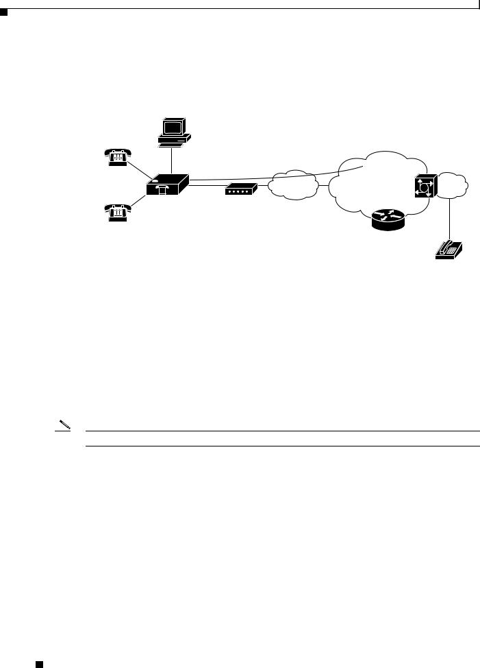
The ATA187, which operates with Cisco voice-packet gateways, makes use of broadband pipes that are deployed through a digital subscriber line (DSL), fixed wireless-cable modem, and other Ethernet connections.
Figure 1-2 ATA 187 as Endpoint in SIP Network
Layer 3 |
Voice |
gateway |
Telephone/fax |
V |
Broadband |
IP infrastructure |
V |
PSTN |
|
Ethernet |
|
|
|
Cisco ATA 187 |
Broadband CPE |
|
(DSL, cable, |
|
fixed wireless) |
SIP proxy
197596
Session Initiation Protocol Overview
Session Initiation Protocol (SIP) is the Internet Engineering Task Force (IETF) standard for real-time calls and conferencing over Internet Protocol (IP). SIP is an ASCII-based, application-layer control protocol (defined in RFC3261) that can be used to establish, maintain, and terminate multimedia sessions or calls between two or more endpoints.
Like other Voice over IP (VoIP) protocols, SIP is designed to address the functions of signaling and session management within a packet telephony network. Signaling allows call information to be carried across network boundaries. Session management provides the ability to control the attributes of an end-to-end call.
Note SIP for the ATA 187 is compliant with RFC2543.
This section contains these topics:
•SIP Capabilities, page 1-2
•Components of SIP, page 1-3
SIP Capabilities
SIP provides these capabilities:
•Determines the availability of the target endpoint. If a call cannot be completed because the target endpoint is unavailable, SIP determines whether the called party is already on the phone or did not answer in the allotted number of rings. SIP then returns a message indicating why the target endpoint was unavailable.
•Determines the location of the target endpoint. SIP supports address resolution, name mapping, and call redirection.
Cisco ATA 187 Analog Telephone Adaptor Administration Guide for SIP (Version 1.0)
1-2 |
OL-21862-01 |
|
|

Chapter 1 Cisco ATA 187 Analog Telephone Adaptor Overview
Session Initiation Protocol Overview
•Determines the media capabilities of the target endpoint. Using the Session Description Protocol (SDP), SIP determines the lowest level of common services between endpoints. Conferences are established using only the media capabilities that are supported by all endpoints.
•Establishes a session between the originating and target endpoint. If the call can be completed, SIP establishes a session between the endpoints. SIP also supports mid-call changes, such as adding another endpoint to the conference or changing the media characteristic or codec.
•Handles the transfer and termination of calls. SIP supports the transfer of calls from one endpoint to another. During a call transfer, SIP establishes a session between the transferee and a new endpoint (specified by the transferring party) and terminates the session between the transferee and the transferring party. At the end of a call, SIP terminates the sessions between all parties. Conferences can consist of two or more users and can be established using multicast or multiple unicast sessions.
Components of SIP
SIP is a peer-to-peer protocol. The peers in a session are called User Agents (UAs). A user agent can function in one of these roles:
•User agent client (UAC)—A client application that initiates the SIP request.
•User agent server (UAS)—A server application that contacts the user when a SIP request is received and returns a response on behalf of the user.
Typically, a SIP endpoint is capable of functioning as both a UAC and a UAS, but functions only as one or the other per transaction. Whether the endpoint functions as a UAC or a UAS depends on the UA that initiated the request.
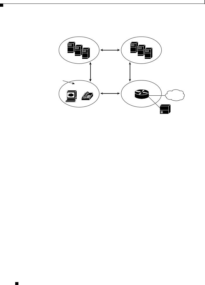
From an architectural standpoint, the physical components of a SIP network can also be grouped into two categories—Clients and servers. Figure 1-3 illustrates the architecture of a SIP network.
Note SIP servers can interact with other application services, such as Lightweight Directory Access Protocol (LDAP) servers, a database application, or an extensible markup language (XML) application. These application services provide back-end services such as directory, authentication, and billable services.
Cisco ATA 187 Analog Telephone Adaptor Administration Guide for SIP (Version 1.0)
|
OL-21862-01 |
1-3 |
|
|
|
Chapter 1 Cisco ATA 187 Analog Telephone Adaptor Overview
Session Initiation Protocol Overview
Figure 1-3 |
SIP Architecture |
SIP proxy and redirect servers
SIP
SIP |
|
SIP |
SIP user agents |
|
|
|
|
SIP gateway |
|
RTP |
PSTN |
|
|
Legacy PBX
72342
SIP Clients
SIP clients include:
•Gateways—Provide call control. Gateways provide many services, the most common being a translation function between SIP conferencing endpoints and other terminal types. This function includes translation between transmission formats and between communications procedures. In addition, the gateway also translates between audio and video codecs and performs call setup and clearing on both the LAN side and the switched-circuit network side.
•Phones—Can act as either a UAS or UAC. The ATA 187 can initiate SIP requests and respond to requests.
SIP Servers
SIP servers include:
•Proxy server—The proxy server is an intermediate device that receives SIP requests from a client and then forwards the requests on the client’s behalf. Proxy servers receive SIP messages and forward them to the next SIP server in the network. Proxy servers can provide functions such as authentication, authorization, network access control, routing, reliable request retransmission, and security.
•Redirect server—Receives SIP requests, strips out the address in the request, checks its address tables for any other addresses that may be mapped to the address in the request, and then returns the results of the address mapping to the client. Redirect servers provide the client with information about the next hop or hops that a message should take, then the client contacts the next hop server or UAS directly.
•Registrar server—Processes requests from UACs for registration of their current location. Registrar servers are often co-located with a redirect or proxy server.
Cisco ATA 187 Analog Telephone Adaptor Administration Guide for SIP (Version 1.0)
1-4 |
OL-21862-01 |
|
|

Chapter 1 Cisco ATA 187 Analog Telephone Adaptor Overview
Hardware Overview
Hardware Overview
The ATA 187 is a compact, easy to install device. Figure 1-4 shows the rear panel of the ATA 187.
Figure 1-4 ATA 187—Rear View
|
|
|
12VDC 1A |
|
LINE 1 |
LINE 2 |
NETWORK |
POWER |
197044 |
|
|
|
|
The unit provides these connectors and indicators:
•12Vb power connector.
•Two RJ-11 FXS (Foreign Exchange Station) ports—The ATA 187 supports two independent RJ-11 phone ports that can connect to any standard analog phone device. Each port supports either voice calls or fax sessions, and both ports can be used simultaneously.
•The ATA 187 has one network port—an RJ-45 10/100BASE-T data port to connect an Ethernet-capable device, such as a computer, to the network.
Note The ATA 187 performs auto-negotiation for duplexity and speed and is capable of 10/100 Mbps, full-duplex operation.
Software Features
The ATA 187 supports these protocols, services and methods:
•Secure Real-Time Transport Protocol, page 1-6
•Name Signaling Event based passthrough, page 1-6
•Transport Layer Security Protocol, page 1-6
•T.38 Fax Relay, page 1-6
•Voice Codecs Supported, page 1-6
•Other Supported Protocols, page 1-6
•ATA 187 SIP Services, page 1-7
•Modem Standards, page 1-7
•Fax Services, page 1-8
•Methods Supported, page 1-8
•Supplementary Services, page 1-9
Cisco ATA 187 Analog Telephone Adaptor Administration Guide for SIP (Version 1.0)
|
OL-21862-01 |
1-5 |
|
|
|

Chapter 1 Cisco ATA 187 Analog Telephone Adaptor Overview
Software Features
Secure Real-Time Transport Protocol
Secure Real-Time Transport Protocol secures voice conversations on the network and provides protection against replay attacks.
Name Signaling Event based passthrough
Name Signaling Event (NSE)-based passthrough is simply thet transport of fax or modem communications using the G.711 codec.
The ATA 187 does not support NSE-based modem passthrough.
Transport Layer Security Protocol
Transport Layer Security (TLS) is a cryptographic protocol that secures data communications such as e-mail on the Internet. TLS is functionally equivalent to Secure Sockets Layer (SSL).
T.38 Fax Relay
The T.38 fax relay feature enables devices to use fax machines to send files over the IP network. In general, when a fax is received, it is converted to an image, sent to the T.38 fax device, and converted back to an analog fax signal. T.38 fax relays configured with voice gateways decode or demodulate the fax signals before they are transported over IP. With the SIP call control protocol, the T.38 fax relay is indicated by Security Description (SDP) entries in the initial SIP INVITE message. After the initial SIP INVITE message, the call is established to switch from voice mode to T.38 mode. Cisco Unified Communications Administration allows you to configure a SIP profile that supports T.38 fax communication.
Voice Codecs Supported
The ATA 187 supports these voice codecs (check your other network devices for the codecs they support):
•G.711µ-law
•G.711A-law
•G.729A
•G.729B
•G.729AB
Other Supported Protocols
The ATA 187 supports these additional protocols:
•802.1Q VLAN tagging
•Cisco Discovery Protocol (CDP)
Cisco ATA 187 Analog Telephone Adaptor Administration Guide for SIP (Version 1.0)
1-6 |
OL-21862-01 |
|
|

Chapter 1 Cisco ATA 187 Analog Telephone Adaptor Overview
Software Features
•Domain Name System (DNS)
•Dynamic Host Configuration Protocol (DHCP)
•Internet Control Message Protocol (ICMP)
•Internet Protocol (IP)
•Real-Time Transport Protocol (RTP)
•Transmission Control Protocol (TCP)
•Trivial File Transfer Protocol (TFTP)
•User Datagram Protocol (UDP)
ATA 187 SIP Services
These services include these features:
•IP address assignment—DHCP-provided or statically configured
•ATA 187 configuration by Cisco Unified Communications Manager configuration interface
•VLAN configuration
•Cisco Discovery Protocol (CDP)
•Low-bit-rate codec selection
•User authentication
•Configurable tones (dial tone, busy tone, alert tone, reorder tone, call waiting tone)
•Dial plans
•SIP proxy server redundancy
•Privacy features
•User-configurable, call waiting, permanent default setting
•Comfort noise during silent period when using G.711
•Advanced audio mode
•Caller ID format
•Ring cadence format
•Silence suppression
•Hookflash detection timing configuration
•Configurable onhook delay
•Type of Service (ToS) configuration for audio and signaling ethernet packets
•Debugging and diagnostic tools
Modem Standards
The ATA 187 supports the following modem standards:
•V.90
•V.92
Cisco ATA 187 Analog Telephone Adaptor Administration Guide for SIP (Version 1.0)
|
OL-21862-01 |
1-7 |
|
|
|

Chapter 1 Cisco ATA 187 Analog Telephone Adaptor Overview
Software Features
•V.44
•K56Flex
•ITU-T V.34 Annex 12
•ITU-T V.34
•V.32bis
•V.32
•V.21
•V.22
•V.23
Fax Services
The ATA 187 supports two modes of fax services, in which fax signals are transmitted using the G.711 codec:
•Fax pass-through mode—Receiver-side Called Station Identification (CED) tone detection with automatic G.711A-law or G.711µ-law switching.
•T.38 Fax Relay mode: The T.38 fax relay feature enables devices to use fax machines to send files over the IP network. In general, when a fax is received, it is converted to an image, sent to the T.38 fax device, and converted back to an analog fax signal. T.38 fax relays configured with voice gateways decode or demodulate the fax signals before they are transported over IP.
Note Success of fax transmission depends on network conditions and fax modem response to these conditions. The network must have reasonably low network jitter, network delay, and packet loss rate.
Methods Supported
The ATA 187 supports these methods. For more information, see RFC3261 (SIP: Session Initiation Protocol).
•REGISTER
•REFER
•INVITE
•BYE
•CANCEL
•NOTIFY
•OPTIONS
•ACK
•SUBSCRIBE
Cisco ATA 187 Analog Telephone Adaptor Administration Guide for SIP (Version 1.0)
1-8 |
OL-21862-01 |
|
|

Chapter 1 Cisco ATA 187 Analog Telephone Adaptor Overview
Installation and Configuration Overview
Supplementary Services
SIP supplementary services are services that you can use to enhance your phone service. For information on how to use these services, see Chapter 7, “Using SIP Supplementary Services”.
The ATA 187 supports these SIP supplementary services:
•Caller ID
•Call-waiting caller ID
•Voice mail indication
•Making a conference call
•Call waiting
•Call forwarding
•Calling-line identification
•Unattended transfer
•Attended transfer
•Shared Line
•SpeedDial
•MeetMe
•Pick Up
•Redial
Installation and Configuration Overview
Table 1-1 provides the basic steps required to install and configure the ATA 187 to make it operational in a typical SIP environment where a large number of ATA 187s must be deployed.
Table 1-1 |
Overview of the Steps Required to Install and Configure the ATA 187 and Make it |
||
|
|
Operational |
|
|
|
|
|
Action |
|
Reference |
|
|
|
|
|
1. |
Plan the network and ATA 187 configuration. |
|
|
|
|
|
|
2. |
Install the Ethernet connection. |
|
|
|
|
|
|
3. |
Install and configure the other network devices. |
|
|
|
|
|
|
4. |
Install the ATA 187 but do not power up the |
Installing the ATA 187, page 3-3 |
|
|
ATA 187 yet. |
|
|
|
|
|
|
5. |
Power up the ATA 187. |
|
|
|
|
|
|
Cisco ATA 187 Analog Telephone Adaptor Administration Guide for SIP (Version 1.0)
|
OL-21862-01 |
1-9 |
|
|
|

Chapter 1 Cisco ATA 187 Analog Telephone Adaptor Overview
Installation and Configuration Overview
|
Cisco ATA 187 Analog Telephone Adaptor Administration Guide for SIP (Version 1.0) |
1-10 |
OL-21862-01 |
C H A P T E R 2
Preparing to Install the ATA 187 on Your Network
The ATA 187 enables you to communicate using voice over a data network. To provide this capability, the ATA 187 depends upon and interacts with several other key Cisco Unified IP Telephony and network components, including Cisco Unified Communications Manager, DNS and DHCP servers, TFTP servers, media resources, and so on.
This chapter focuses on the interactions between the ATA 187, Cisco Unified Communications Manager, DNS and DHCP servers, TFTP servers, and switches. It also describes options for powering the
ATA 187.
For related information about voice and IP communications, see this URL:
http://www.cisco.com/en/US/products/sw/voicesw/index.html
This chapter provides an overview of the interaction between the ATA 187 and other key components of the Voice over IP (VoIP) network. It includes these topics:
•Understanding Interactions with Other Cisco Unified IP Communications Products, page 2-1
•Providing Power to the ATA 187, page 2-2
•Understanding Phone Configuration Files, page 2-3
•Understanding the ATA 187 Startup Process, page 2-4
•Adding the ATA 187 to the Cisco Unified Communications Manager Database, page 2-5
•Determining the MAC Address of an ATA 187, page 2-7
Understanding Interactions with Other Cisco
Unified IP Communications Products
To function in the IP telephony network, the ATA 187 must be connected to a networking device, such as a Cisco Catalyst switch. You must also register the ATA 187 with a Cisco Unified Communications Manager system before sending and receiving calls.
This section includes information on Understanding How the ATA 187 Interacts with Cisco
Unified Communications Manager, page 2-2.
Cisco ATA 187 Analog Telephone Adaptor Administration Guide for SIP (Version 1.0)
|
OL-21862-01 |
2-1 |
|
|
|

Chapter 2 Preparing to Install the ATA 187 on Your Network
Providing Power to the ATA 187
Understanding How the ATA 187 Interacts with Cisco Unified Communications Manager
Cisco Unified Communications Manager is an open and industry-standard call processing system. Cisco Unified Communications Manager software sets up and tears down calls between phones connected to the ATA 187, integrating traditional PBX functionality with the corporate IP network. Cisco Unified Communications Manager manages the components of the IP telephony system—the phones, the access gateways, and the resources necessary for features such as call conferencing and route planning. Cisco Unified Communications Manager also provides:
•Firmware for devices
•Authentication and encryption (if configured for the telephony system)
•Configuration and CTL files via the TFTP service
•Phone registration
•Call preservation, so that a media session continues if signaling is lost between the primary Communications Manager and a phone
For information about configuring Cisco Unified Communications Manager to work with the IP devices described in this chapter, see Cisco Unified Communications Manager Administration Guide, Cisco Unified Communications Manager System Guide, and Cisco Unified Communications Manager Security Guide.
Providing Power to the ATA 187
The ATA 187 is powered with external power. External power is provided through a separate power supply.
The following sections provide more information about powering a ATA 187:
•Power Guidelines, page 2-2
•Power Outage, page 2-2
•Understanding Phone Configuration Files, page 2-3
Power Guidelines
The following power type and guideline applies to external power for the ATA 187:
•Power Type—External power (Provided through the Universal AC external power supply)
•Guidelines—The ATA 187 uses the Universal AC power supply 110/240V
Power Outage
Your accessibility to emergency service through the phone is dependent on the phone being powered. If there is an interruption in the power supply, Service and Emergency Calling Service dialing will not function until power is restored. In the case of a power failure or disruption, you may need to reset or reconfigure equipment before using the Service or Emergency Calling Service dialing.
Cisco ATA 187 Analog Telephone Adaptor Administration Guide for SIP (Version 1.0)
2-2 |
OL-21862-01 |
|
|

Chapter 2 Preparing to Install the ATA 187 on Your Network
Understanding Phone Configuration Files
Understanding Phone Configuration Files
Configuration files for a phone are stored on the TFTP server and define parameters for connecting to Cisco Unified Communications Manager. In general, any time you make a change in Cisco
Unified Communications Manager that requires the phone to be reset, a change is automatically made to the phone’s configuration file. If the system needs to reset or restart, both ports must reset or restart at the same time.
Configuration files also contain information about which image load the phone should be running. If this image load differs from the one that is currently loaded on a phone, the phone contacts the TFTP server to request the required load files. (These files are digitally signed to ensure the authenticity of the file source.)
In addition, if the device security mode in the configuration file is set to Authenticated and the CTL file on the phone has a valid certificate for Cisco Unified Communications Manager, the phone establishes a TLS connection to Cisco Unified Communications Manager. Otherwise, the phone establishes a TCP connection. For SIP phones, a TLS connection requires that the transport protocol in the phone configuration file be set to TLS, which corresponds to the transport type in the SIP Security Profile in Cisco Unified Communications Manager.
Note If the device security mode in the configuration file is set to Authenticated or Encrypted, but the phone has not received a CTL file, the phone tries four times to obtain it so it can register securely.
Note Cisco Extension Mobility Cross Cluster is an exception, in that the phone permits a TLS connection to Cisco Unified Communications Manager for secure signaling even without the CTL file.
If you configure security-related settings in Cisco Unified Communications Manager Administration, the phone configuration file will contain sensitive information. To ensure the privacy of a configuration file, you must configure it for encryption. For detailed information, see Configuring Encrypted Phone Configuration Files in Cisco Unified Communications Manager Security Guide.
A phone accesses a default configuration file named XmlDefault.cnf.xml only when the phone has not received a valid Trust List file containing a certificate assigned to the Cisco Unified Communications Manager and TFTP.
If auto registration is not enabled and you did not add the phone to the Cisco Unified Communications Manager database, the phone does not attempt to register with Cisco Unified Communications Manager. The phone continually displays the “Configuring IP” message until you either enable auto-registration or add the phone to the Cisco Unified Communications Manager database.
If the phone has registered before, the phone accesses the configuration file named
ATA<mac_address>.cnf.xml, where mac_address is the MAC address of the phone.
For SIP phones, the TFTP server generates these SIP configuration files:
•SIP IP Phone:
–For unsigned and unencrypted files—ATA<mac>.cnf.xml
–For signed files—ATA<mac>.cnf.xml.sgn
–For signed and encrypted files—ATA<mac>.cnf.xml.enc.sgn
•Dial Plan—<dialplan>.xml
–No support “,” for second dial tone; “,” will be ignored
Cisco ATA 187 Analog Telephone Adaptor Administration Guide for SIP (Version 1.0)
|
OL-21862-01 |
2-3 |
|
|
|

Chapter 2 Preparing to Install the ATA 187 on Your Network
Understanding the ATA 187 Startup Process
–No support > for configuring termination key
–No support + dial pattern which contains + will be ignored
–Maximum length of match string is 196
–Maximum length of a dial pattern is 4095
–Maximum rule set in one dial pattern is 100
The filenames are derived from the MAC Address and Description fields in the Phone Configuration window of Cisco Unified Communications Manager Administration. The MAC address uniquely identifies the phone. For more information see the Cisco Unified Communications Manager Administration Guide.
For more information about how the phone interacts with the TFTP server, see the Cisco Unified Communications Manager System Guide, Cisco TFTP section.
Understanding the ATA 187 Startup Process
When connecting to the VoIP network, the ATA 187 goes through a standard startup process, as described in Table 2-1. Depending on your specific network configuration, not all of these process steps may occur on your ATA 187.
Table 2-1 |
ATA 187 Startup Process |
|
|
|
|
Task |
Purpose |
Related Topics |
|
|
|
1. |
Obtaining Power. |
See Providing Power to the ATA 187, page 2-2. |
|
The ATA 187 uses external power. |
|
|
|
|
2. |
Loading the Stored Image. |
|
|
The ATA 187 has non-volatile flash memory in which it |
|
|
stores firmware images and user-defined preferences. At |
|
|
startup, the phone runs a bootstrap loader that loads a |
|
|
phone image stored in flash memory. Using this image, the |
|
|
phone initializes its software and hardware. |
|
|
|
|
3. |
Obtaining an IP Address. |
|
|
If the ATA 187 is using DHCP to obtain an IP address, the |
|
|
device queries the DHCP server to obtain one. If you are |
|
|
not using DHCP in your network, you must assign static IP |
|
|
addresses to each device locally. |
|
|
|
|
4. |
Requesting the CTL file. |
See the Cisco Unified Communications Manager |
|
The TFTP server stores the CTL file. This file contains the |
Security Guide, Configuring the Cisco CTL |
|
certificates necessary for establishing a secure connection |
Client. |
|
between the device and Cisco Unified Communications |
|
|
Manager. |
|
|
|
|
Cisco ATA 187 Analog Telephone Adaptor Administration Guide for SIP (Version 1.0)
2-4 |
OL-21862-01 |
|
|
Loading...