


 Loading...
Cisco ASA 5500-X Series Hardware
Installation Guide
Cisco ASA 5512-X, ASA 5515-X, ASA 5525-X, ASA 5545-X, and ASA 5555-X
Cisco Systems, Inc.
www.cisco.com
Cisco has more than 200 offices worldwide. Addresses, phone numbers, and fax numbers are listed on the Cisco website at www.cisco.com/go/offices.
THE SPECIFICATIONS AND INFORMATION REGARDING THE PRODUCTS IN THIS MANUAL ARE SUBJECT TO CHANGE WITHOUT NOTICE. ALL STATEMENTS, INFORMATION, AND RECOMMENDATIONS IN THIS MANUAL ARE BELIEVED TO BE ACCURATE BUT ARE PRESENTED WITHOUT WARRANTY OF ANY KIND, EXPRESS OR IMPLIED. USERS MUST TAKE FULL RESPONSIBILITY FOR THEIR APPLICATION OF ANY PRODUCTS.
THE SOFTWARE LICENSE AND LIMITED WARRANTY FOR THE ACCOMPANYING PRODUCT ARE SET FORTH IN THE INFORMATION PACKET THAT SHIPPED WITH THE PRODUCT AND ARE INCORPORATED HEREIN BY THIS REFERENCE. IF YOU ARE UNABLE TO LOCATE THE SOFTWARE LICENSE OR LIMITED WARRANTY, CONTACT YOUR CISCO REPRESENTATIVE FOR A COPY.
The following information is for FCC compliance of Class A devices: This equipment has been tested and found to comply with the limits for a Class A digital device, pursuant to part 15 of the FCC rules. These limits are designed to provide reasonable protection against harmful interference when the equipment is operated in a commercial environment. This equipment generates, uses, and can radiate radio-frequency energy and, if not installed and used in accordance with the instruction manual, may cause harmful interference to radio communications. Operation of this equipment in a residential area is likely to cause harmful interference, in which case users will be required to correct the interference at their own expense.
The following information is for FCC compliance of Class B devices: This equipment has been tested and found to comply with the limits for a Class B digital device, pursuant to part 15 of the FCC rules. These limits are designed to provide reasonable protection against harmful interference in a residential installation. This equipment generates, uses and can radiate radio frequency energy and, if not installed and used in accordance with the instructions, may cause harmful interference to radio communications.
However, there is no guarantee that interference will not occur in a particular installation. If the equipment causes interference to radio or television reception, which can be determined by turning the equipment off and on, users are encouraged to try to correct the interference by using one or more of the following measures:
•Reorient or relocate the receiving antenna.
•Increase the separation between the equipment and receiver.
•Connect the equipment into an outlet on a circuit different from that to which the receiver is connected.
•Consult the dealer or an experienced radio/TV technician for help.
Modifications to this product not authorized by Cisco could void the FCC approval and negate your authority to operate the product.
The Cisco implementation of TCP header compression is an adaptation of a program developed by the University of California, Berkeley (UCB) as part of UCB’s public domain version of the UNIX operating system. All rights reserved. Copyright © 1981, Regents of the University of California.
NOTWITHSTANDING ANY OTHER WARRANTY HEREIN, ALL DOCUMENT FILES AND SOFTWARE OF THESE SUPPLIERS ARE PROVIDED “AS IS” WITH ALL FAULTS. CISCO AND THE ABOVE-NAMED SUPPLIERS DISCLAIM ALL WARRANTIES, EXPRESSED OR IMPLIED, INCLUDING, WITHOUT LIMITATION, THOSE OF MERCHANTABILITY, FITNESS FOR A PARTICULAR PURPOSE AND NONINFRINGEMENT OR ARISING FROM A COURSE OF DEALING, USAGE, OR TRADE PRACTICE.
IN NO EVENT SHALL CISCO OR ITS SUPPLIERS BE LIABLE FOR ANY INDIRECT, SPECIAL, CONSEQUENTIAL, OR INCIDENTAL DAMAGES, INCLUDING, WITHOUT LIMITATION, LOST PROFITS OR LOSS OR DAMAGE TO DATA ARISING OUT OF THE USE OR INABILITY TO USE THIS MANUAL, EVEN IF CISCO OR ITS SUPPLIERS HAVE BEEN ADVISED OF THE POSSIBILITY OF SUCH DAMAGES.
Cisco and the Cisco logo are trademarks or registered trademarks of Cisco and/or its affiliates in the U.S. and other countries. To view a list of Cisco trademarks, go to this URL: www.cisco.com/go/trademarks. Third-party trademarks mentioned are the property of their respective owners. The use of the word partner does not imply a partnership relationship between Cisco and any other company. (1110R)
Any Internet Protocol (IP) addresses and phone numbers used in this document are not intended to be actual addresses and phone numbers. Any examples, command display output, network topology diagrams, and other figures included in the document are shown for illustrative purposes only. Any use of actual IP addresses or phone numbers in illustrative content is unintentional and coincidental.
Cisco ASA 5500-X Series Hardware Installation Guide
© 2012-2013 Cisco Systems, Inc. All rights reserved.

C O N T E N T S
|
About This Guide |
vii |
|
|
|
|
|
|
|
Contents |
vii |
|
|
|
|
|
|
|
Document Objectives |
vii |
|
|
|
|||
|
Document Conventions |
vii |
|
|
||||
|
Installation Warnings |
viii |
|
|
|
|||
|
Where to Find Safety and Warning Information xii |
|||||||
|
Related Documentation |
xii |
|
|
||||
|
Obtaining Documentation and Submitting a Service Request xii |
|||||||
|
Information about the ASA 5500-X |
|
|
|||||
C H A P T E R 1 |
1-1 |
|
||||||
|
Cisco ASA 5500-X Series Chassis Overview |
1-2 |
||||||
|
Internal and External USB Flash Drives 1-2 |
|
||||||
|
Internal USB Drive |
1-2 |
|
|
||||
|
(Optional) External USB Drives |
1-2 |
|
|||||
|
Online Insertion and Removal Support |
1-3 |
||||||
|
FAT 32 File System |
1-3 |
|
|
||||
|
Viewing Flash Memory |
1-3 |
|
|
||||
|
Solid State Drives |
1-3 |
|
|
|
|
||
|
Management 0/0 Interface |
1-4 |
|
|
||||
|
Alarm LED |
1-4 |
|
|
|
|
|
|
|
ASA 5500-X I/O Cards |
1-5 |
|
|
||||
|
SFP Modules |
1-5 |
|
|
|
|
|
|
|
ASA Chassis Panels |
1-6 |
|
|
|
|||
|
Front Panel LEDs |
1-6 |
|
|
|
|||
|
Rear Panel LEDs |
|
1-9 |
|
|
|
||
|
Rear Panel Ports |
|
1-11 |
|
|
|||
|
Power Supply |
1-13 |
|
|
|
|
|
|
|
Hardware Specifications |
1-15 |
|
|
||||
|
Console Cable Pinouts |
1-16 |
|
|
||||
|
RJ-45 Console Cable |
1-16 |
|
|
||||
|
RJ-45 to DB-9 Console Adapter |
1-18 |
|
|||||
Cisco ASA 5500-X Series Hardware Installation Guide
iii

Contents
C H A P T E R |
2 |
Preparing for Installation |
2-1 |
|
|
|
|
|
|
|
|
|
|
Installation Overview |
2-1 |
|
|
|
|
|
|
|
|
|
|
Safety Recommendations |
2-1 |
|
|
|
|
|
|
|
|
|
|
Maintaining Safety with Electricity |
2-2 |
|
|
|
|
||||
|
|
Preventing Electrostatic Discharge Damage |
2-3 |
|
|
|
|||||
|
|
Working in an ESD Environment |
2-3 |
|
|
|
|
|
|||
|
|
General Site Requirements |
2-3 |
|
|
|
|
|
|
|
|
|
|
Site Environment |
2-4 |
|
|
|
|
|
|
|
|
|
|
Preventive Site Configuration |
2-4 |
|
|
|
|
|
|||
|
|
Power Supply Considerations |
2-4 |
|
|
|
|
|
|||
|
|
Configuring Equipment Racks |
2-6 |
|
|
|
|
|
|||
|
|
Installing and Connecting the ASA 5500-X |
|
|
|
|
|
||||
C H A P T E R |
3 |
3-1 |
|
|
|
|
|||||
|
|
Rack Mounting the Chassis |
3-1 |
|
|
|
|
|
|
|
|
|
|
Rack Mounting Guidelines |
3-1 |
|
|
|
|
|
|
||
|
|
Rack Mounting the ASA 5512-X, 5515-X, and 5525-X With Brackets |
3-2 |
|
|||||||
|
|
Rack Mounting the ASA 5500-X Chassis with Slide Rail Mounting System |
3-4 |
||||||||
|
|
Preparing the ASA 5512-X, ASA 5515-X, or ASA 5525-X to Use an Optional Slide Rail Rack Mount |
|||||||||
|
|
System 3-4 |
|
|
|
|
|
|
|
|
|
|
|
Rack Mounting the Chassis with the Slide Rail Mounting System |
3-5 |
|
|||||||
|
|
Connecting Cables, Turning on Power, and Verifying Connectivity |
3-13 |
|
|
||||||
|
|
Maintenance and Upgrade Procedures for the ASA 5500-X 4-1 |
|
|
|
||||||
C H A P T E R |
4 |
|
|
|
|||||||
|
|
Removing and Replacing the Chassis Cover |
4-1 |
|
|
|
|
||||
|
|
Removing the Chassis Cover |
4-1 |
|
|
|
|
|
|
||
|
|
Replacing the Chassis Cover |
4-2 |
|
|
|
|
|
|
||
|
|
Installing an I/O Card |
4-3 |
|
|
|
|
|
|
|
|
|
|
Installing an I/O Card in the Cisco ASA 5512-X, 5515-X, and 5525-X Chassis |
4-3 |
||||||||
|
|
Installing an I/O Card in the Cisco ASA 5545-X and 5555-X Chassis |
4-7 |
|
|||||||
|
|
Installing and Removing the SFP Modules |
4-11 |
|
|
|
|
||||
|
|
Installing the SFP Module 4-11 |
|
|
|
|
|
|
|||
|
|
Removing the SFP Module |
4-12 |
|
|
|
|
|
|
||
|
|
Removing and Installing the Power Supply |
4-13 |
|
|
|
|
||||
|
|
Removing and Installing the AC Power Supply |
4-13 |
|
|
|
|||||
|
|
Installing the DC Input Power |
4-15 |
|
|
|
|
|
|||
|
|
Removing and Installing the DC Power Supply |
4-19 |
|
|
|
|||||
|
|
Installing and Removing the Solid State Drive for the ASA CX SSP |
4-21 |
|
|
||||||
|
|
Installation Scenarios |
4-21 |
|
|
|
|
|
|
|
|
Cisco ASA 5500-X Series Hardware Installation Guide
iv

Contents
Installing and Removing SSDs 4-22
I N D E X
Cisco ASA 5500-X Series Hardware Installation Guide
v

Contents
Cisco ASA 5500-X Series Hardware Installation Guide
vi

About This Guide
Revised: September 17, 2013
Contents
This preface includes the following sections:
•Document Objectives, page vii
•Document Conventions, page vii
•Installation Warnings, page viii
•Where to Find Safety and Warning Information, page xii
•Related Documentation, page xii
•Obtaining Documentation and Submitting a Service Request, page xii
Document Objectives
This guide describes how to install and maintain the Cisco ASA 5500-X series appliances. Information in this guide applies to the following Cisco ASA 5500-X Series models: ASA 5512-X, ASA 5515-X, ASA 5525-X, ASA 5545-X, and ASA 5555-X. References to “Cisco ASA 5500-X Series” and “ASA” apply to all previously listed models unless specifically noted otherwise.
Document Conventions
This document uses the following conventions:
Convention |
Indication |
|
|
bold font |
Commands and keywords and user-entered text appear in bold font. |
|
|
italic font |
Document titles, new or emphasized terms, and arguments for which you supply |
|
values are in italic font. |
|
|
[ ] |
Elements in square brackets are optional. |
|
|
Cisco ASA 5500-X Series Hardware Installation Guide
vii

|
|
|
|
|
|
|
|
|
|
|
|
|
|
|
|
|
|
|
|
{x | y | z } |
Required alternative keywords are grouped in braces and separated by |
|
|
|
|
|
|
vertical bars. |
|
|
|
|
|
|
|
|
|
[ x | y | z ] |
Optional alternative keywords are grouped in brackets and separated by |
|
|
|
|
|
|
vertical bars. |
|
|
|
|
|
|
|
|
|
string |
A nonquoted set of characters. Do not use quotation marks around the string or |
|
|
|
|
|
|
the string will include the quotation marks. |
|
|
|
|
|
|
|
|
|
courier font |
Terminal sessions and information the system displays appear in courier font. |
|
|
|
|
|
|
|
|
|
|
courier bold font |
Commands and keywords and user-entered text appear in bold courier font. |
|
|
|
|
|
|
|
|
|
|
courier italic font |
Arguments for which you supply values are in courier italic font. |
|
|
|
|
|
|
|
|
< |
> |
Nonprinting characters such as passwords are in angle brackets. |
|
||
|
|
|
|
|
|
[ |
] |
Default responses to system prompts are in square brackets. |
|
||
|
|
|
|
||
!, # |
An exclamation point (!) or a pound sign (#) at the beginning of a line of code |
|
|||
|
|
|
|
indicates a comment line. |
|
|
|
|
|
|
|
Note Means reader take note.
Tip Means the following information will help you solve a problem.
Caution Means reader be careful. In this situation, you might perform an action that could result in equipment damage or loss of data.
Installation Warnings
Be sure to read the Regulatory Compliance and Safety Information document at before installing the chassis. This document contains important safety information. This section includes the following warnings:
•Power Supply Disconnection Warning, page ix
•Jewelry Removal Warning, page ix
•Wrist Strap Warning, page ix
•More than One Power Supply Warning, page ix
•Work During Lightning Activity Warning, page ix
•Installation Instructions Warning, page x
•Chassis Warning for Rack-Mounting and Servicing, page x
•SELV Circuit Warning, page x
•Ground Conductor Warning, page x
•Blank Faceplates and Cover Panels Warning, page x
•Product Disposal Warning, page x
•Short-Circuit Protection Warning, page xi
Cisco ASA 5500-X Series Hardware Installation Guide
viii

•Compliance with Local and National Electrical Codes Warning, page xi
•DC Power Connection Warning, page xi
•AC Power Disconnection Warning, page xi
•TN Power Warning, page xi
•48 VDC Power System, page xi
•Multiple Power Cord, page xi
•Circuit Breaker (15A) Warning, page xi
•Grounded Equipment Warning, page xii
•Safety Cover Requirement, page xii
•Faceplates and Cover Panel Requirement, page xii
Power Supply Disconnection Warning
Warning Before working on a chassis or working near power supplies, unplug the power cord on AC units; disconnect the power at the circuit breaker on DC units. Statement 12
Jewelry Removal Warning
Warning Before working on equipment that is connected to power lines, remove jewelry (including rings, necklaces, and watches). Metal objects will heat up when connected to power and ground and can cause serious burns or weld the metal object to the terminals. Statement 43
Wrist Strap Warning
Warning During this procedure, wear grounding wrist straps to avoid ESD damage to the card. Do not directly touch the backplane with your hand or any metal tool, or you could shock yourself. Statement 94
More than One Power Supply Warning
Warning This unit has more than one power supply connection; all connections must be removed completely to completely remove power from the unit. Statement 102
Work During Lightning Activity Warning
Warning Do not work on the system or connect or disconnect cables during periods of lightning activity.
Statement 1001
Cisco ASA 5500-X Series Hardware Installation Guide
ix
Installation Instructions Warning
Warning Read the installation instructions before connecting the system to the power source. Statement 1004
Chassis Warning for Rack-Mounting and Servicing
Warning To prevent bodily injury when mounting or servicing this unit in a rack, you must take special precautions to ensure that the system remains stable. The following guidelines are provided to ensure your safety: This unit should be mounted at the bottom of the rack if it is the only unit in the rack.When mounting this unit in a partially filled rack, load the rack from the bottom to the top with the heaviest component at the bottom of the rack.If the rack is provided with stabilizing devices, install the stabilizers before mounting or servicing the unit in the rack. Statement 1006
SELV Circuit Warning
Warning To avoid electric shock, do not connect safety extra-low voltage (SELV) circuits to telephone-network voltage (TNV) circuits. LAN ports contain SELV circuits, and WAN ports contain TNV circuits. Some LAN and WAN ports both use RJ-45 connectors. Use caution when connecting cables. Statement 1021
Ground Conductor Warning
Warning This equipment must be grounded. Never defeat the ground conductor or operate the equipment in the absence of a suitably installed ground conductor. Contact the appropriate electrical inspection authority or an electrician if you are uncertain that suitable grounding is available. Statement 1024
Blank Faceplates and Cover Panels Warning
Warning Blank faceplates and cover panels serve three important functions: they prevent exposure to hazardous voltages and currents inside the chassis; they contain electromagnetic interference (EMI) that might disrupt other equipment; and they direct the flow of cooling air through the chassis. Do not operate the system unless all cards, faceplates, front covers, and rear covers are in place. Statement 1029
Product Disposal Warning
Warning Ultimate disposal of this product should be handled according to all national laws and regulations.
Statement 1040
Cisco ASA 5500-X Series Hardware Installation Guide
x
Short-Circuit Protection Warning
Warning This product requires short-circuit (overcurrent) protection, to be provided as part of the building installation. Install only in accordance with national and local wiring regulations. Statement 1045
Compliance with Local and National Electrical Codes Warning
Warning Installation of the equipment must comply with local and national electrical codes. Statement 1074
DC Power Connection Warning
Warning After wiring the DC power supply, remove the tape from the circuit breaker switch handle and reinstate power by moving the handle of the circuit breaker to the ON position. Statement 8
AC Power Disconnection Warning
Warning Before working on a chassis or working near power supplies, unplug the power cord on AC units.
Statement 246
TN Power Warning
Warning The device is designed to work with TN power systems. Statement 19
48 VDC Power System
Warning The customer 48 volt power system must provide reinforced insulation between the primary AC power and the 48 VDC output. Statement 128
Multiple Power Cord
Warning This unit has more than one power cord. To reduce the risk of electric shock when servicing a unit, disconnect the power cord of the power strip that the unit is plugged into. Statement 137
Circuit Breaker (15A) Warning
Warning This product relies on the building’s installation for short-circuit (overcurrent) protection. Ensure that a fuse or circuit breaker no larger than 120 VAC, 15A U.S. (240 VAC, 10A international) is used on the phase conductors (all current-carrying conductors). Statement 13
Cisco ASA 5500-X Series Hardware Installation Guide
xi
Grounded Equipment Warning
Warning This equipment is intended to be grounded. Ensure that the host is connected to earth ground during normal use. Statement 39
Safety Cover Requirement
Warning The safety cover is an integral part of the product. Do not operate the unit without the safety cover installed. Operating the unit without the cover in place will invalidate the safety approvals and pose a risk of fire and electrical hazards. Statement 117
Faceplates and Cover Panel Requirement
Warning Blank faceplates and cover panels serve three important functions: they prevent exposure to hazardous voltages and currents inside the chassis; they contain electromagnetic interference (EMI) that might disrupt other equipment; and they direct the flow of cooling air through the chassis. Do not operate the system unless all cards, faceplates, front covers, and rear covers are in place. Statement 142
Where to Find Safety and Warning Information
For safety and warning information, see the Regulatory Compliance and Safety Information document at the following URL:
http://www.cisco.com/en/US/docs/security/asa/roadmap/asaroadmap.html#wp57708
This RCSI document describes the international agency compliance and safety information for the Cisco ASA 5500-X series. It also includes translations of the safety warnings used in this guide.
Related Documentation
For a complete list of the Cisco ASA 5500-X series documentation and where to find it, see the documentation roadmap at the following URL:
http://www.cisco.com/en/US/docs/security/asa/roadmap/asaroadmap.html
Obtaining Documentation and Submitting a Service Request
For information on obtaining documentation, using the Cisco Bug Search Tool (BST), submitting a service request, and gathering additional information, see What’s New in Cisco Product Documentation at: http://www.cisco.com/en/US/docs/general/whatsnew/whatsnew.html.
Subscribe to What’s New in Cisco Product Documentation, which lists all new and revised Cisco technical documentation, as an RSS feed and deliver content directly to your desktop using a reader application. The RSS feeds are a free service.
Cisco ASA 5500-X Series Hardware Installation Guide
xii

Cisco ASA 5500-X Series Hardware Installation Guide
xiii

Cisco ASA 5500-X Series Hardware Installation Guide
xiv
C H A P T E R 1
Information about the ASA 5500-X
This chapter describes the Cisco ASA 5512-X, 5515-X, 5525-X, 5545-X, and 5555-X models. We recommend that you read this entire guide before beginning any of the procedures contained herein.
Warning Only trained and qualified personnel should install, replace, or service this equipment. Statement 49
Caution Read the safety warnings in the Regulatory Compliance and Safety Information document for the Cisco ASA 5500-X, and follow proper safety procedures when performing any tasks in this guide. See http://www.cisco.com/go/asadocs for links to the RCSI and other ASA documents.
This chapter includes the following topics:
•Cisco ASA 5500-X Series Chassis Overview, page 1-2
•Internal and External USB Flash Drives, page 1-2
•Solid State Drives, page 1-3
•Management 0/0 Interface, page 1-4
•Alarm LED, page 1-4
•ASA 5500-X I/O Cards, page 1-5
•SFP Modules, page 1-5
•ASA Chassis Panels, page 1-6
•Power Supply, page 1-13
•Hardware Specifications, page 1-15
•Console Cable Pinouts, page 1-16
Cisco ASA 5500-X Series Hardware Installation Guide
1-1

Chapter 1 Information about the ASA 5500-X
Cisco ASA 5500-X Series Chassis Overview
Cisco ASA 5500-X Series Chassis Overview
This guide supports the Cisco ASA 5500-X series models, which includes the ASA 5512-X,
ASA 5515-X, ASA 5525-X, ASA 5545-X, and ASA 5555-X.
The Cisco ASA 5500-X series is a family of next-generation mid-range ASAs that are built on the same security platform as the rest of the ASA family. These next-generation ASAs provide more firewall throughput (4X firewall throughput), better scaling, more Ethernet ports (up to 14 GE ports), optional ASA CX SSP or ASA IPS SSP software modules, and redundant power supplies on the 5545-X and 5555-X models.
For More Information
•For information about ASA 5500-X performance, see the “Hardware Specifications” section on page 1-15.
•For information about ASA IPS functionality, see Cisco Intrusion Prevention System documentation:
http://www.cisco.com/en/US/products/hw/vpndevc/ps4077/products_documentation_roadmaps_lis t.html
•For information about ASA CX functionality, see: http://www.cisco.com/en/US/docs/security/asacx/roadmap/asacxprsmroadmap.html
Internal and External USB Flash Drives
The Cisco ASA 5500-X series chassis have internal and (optional) external USB drives.
•Internal USB Drive, page 1-2
•(Optional) External USB Drives, page 1-2
•Online Insertion and Removal Support, page 1-3
•FAT 32 File System, page 1-3
Internal USB Drive
An embedded USB (eUSB) device is used as the internal flash (disk0). See the “Hardware
Specifications” section on page 1-15 for the size shipped with each model.
(Optional) External USB Drives
The ASA 5500-X series supports external USB flash drives for data storage. The ASA 5500-X series use disk1 as the external USB flash drive identifier. When the ASA is powered on, an inserted USB flash drive is mounted to disk1 and available for you to use. Additionally, the file system commands that are available to disk0 are also available to disk1, including copy, format, delete, mkdir, pwd, cd, and so on. When you remove the USB flash drive, the system unmounts disk1, and disk1 becomes an invalid file system label that you can no longer access.
If you insert a USB drive with more than one partition, only the first partition is mounted.
Cisco ASA 5500-X Series Hardware Installation Guide
1-2

Chapter 1 Information about the ASA 5500-X
Solid State Drives
Online Insertion and Removal Support
While the ASA back panel has two USB slots, only one is supported for Online Insertion and Removal (OIR), with priority given to the USB drive that was inserted first. For example, based on the time sequence, the first inserted USB flash drive is mounted to disk1, regardless of the slot in which you insert it. When you insert a second USB device, an error message displays on the console to notify you that an extra, unsupported USB flash drive exists. Removing either one of the USB devices does not change the priority that you just established. To change the priority you must safely remove the USB device and begin again to establish the desired priority.
FAT 32 File System
The ASA 5500-X series supports only FAT32 formatted file systems for the eUSB and external USB drives. If you insert an external USB drive that is not in FAT 32 format, the system mounting process fails, and you receive an error message. You can enter the format disk1: command to format the partition to FAT 32 and mount the partition to disk1 again; however, data might be lost.
Viewing Flash Memory
Check the amount of free flash memory on the ASA by doing the following:
•ASDM—Choose Tools > File Management. The amount of available memory appears on the bottom left in the pane.
•CLI—In privileged EXEC mode, enter the dir command. The amount of available memory appears at the bottom of the output.
Solid State Drives
You must install a Cisco Solid State Drive (SSDs) for use with the ASA CX SSP. Only Cisco SSDs are supported. Currently, the ASA CX SSP is the only process that can use the SSD for storage. You can install one SSD in the ASA 5512-X, ASA 5515-X, and ASA 5525-X. You can install two SSDs in a RAID 1 configuration in the ASA 5545-X and ASA 5555-X.
Note When you install an SSD for the first time, you must reload the ASA and then reimage the ASA CX SSP.
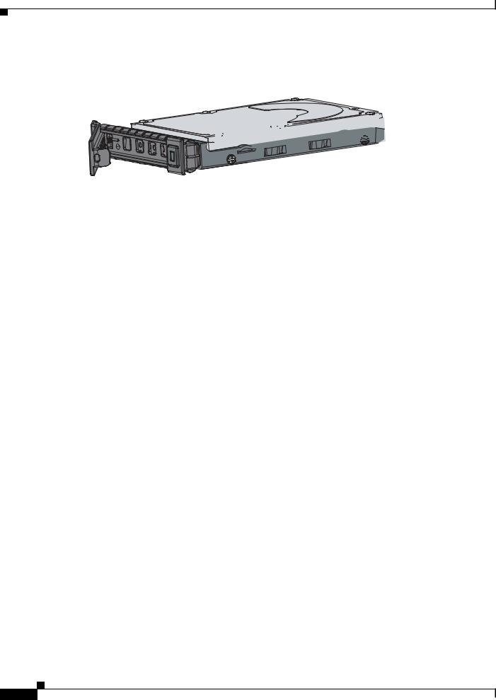
The SSD is hot-swappable. The SSD resides in a carrier, which you install into the drive bay. You can use the SSD with an AC or DC power supply.
Cisco ASA 5500-X Series Hardware Installation Guide
1-3
Chapter 1 Information about the ASA 5500-X
Management 0/0 Interface
Figure 1-1 shows the SSD in the carrier that it is shipped in.
Figure 1-1 |
SSD in Carrier |


 334564
Management 0/0 Interface
You manage the ASA through the Management 0/0 interface. The Management 0/0 interface has the following characteristics:
•No through traffic support
•No subinterface support
•No priority queue support
•No multicast MAC support
•The IPS or CX SSP software module and the ASA share the Management 0/0 interface; however, each has its own separate MAC address and IP address. You must configure the module IP address within the module operating system. However, you configure physical characteristics (such as enabling the interface) on the ASA.
The Management 0/0 interface is configured for management-only traffic, and you cannot disable management-only for the Management interface. Also, because the ASA 5500-X models do not allow subinterfaces on the Management interface, for per-context management, you must connect to a data interface for management.
The Management 0/0 interface is configured for ASDM access as part of the default factory configuration.
For More Information
For more information, see the “Rear Panel Ports” section on page 1-11.
Alarm LED
The ASA 5500-X series chassis perform autonomous environment monitoring to poll all external sensors and monitor operating conditions. In the event of damage to certain internal components or surpassed temperature thresholds, the system activates an alarm LED to notify you of a critical condition. For example, the alarm LED is activated by firmware in the event of various critical over-voltage and over-temperature conditions, as well as when the ASA has missing or unrecognized internal chip components. When the alarm LED lights, you can find details about the system condition from the system message that appears on the console or by entering the show environment or show controller pci command.
Cisco ASA 5500-X Series Hardware Installation Guide
1-4

Chapter 1 Information about the ASA 5500-X
ASA 5500-X I/O Cards
ASA 5500-X I/O Cards
The Cisco ASA 5500-X Series 6-port Gigabit Ethernet interface cards extend the I/O capabilities of the ASA 5525-X, ASA 5545-X, and ASA 5555-X models by providing additional Gigabit Ethernet ports.
The I/O cards provide the following benefits:
•Segmentation of network traffic into separate security zones
•Fiber optic cable connectivity for communicating over long distances
•Load sharing of traffic and protection against link failure by using EtherChannel
•Support for Jumbo Ethernet frames of up to 9000 bytes
•Protection for Active/Active failover and of full-mesh firewall deployments against cable failure
For More Information
For information about installing an I/O card in your ASA, see Chapter 4, “Maintenance and Upgrade Procedures for the ASA 5500-X.”
SFP Modules
The ASA uses a field-replaceable SFP module to establish Gigabit Ethernet connections. Table 1-1 lists the supported SFP modules.
Table 1-1 |
Supported SFP Modules |
|
|
|
|
|
|
SFP Module |
|
Type of Connection |
Cisco Part Number |
|
|
|
|
1000BASE-LX/LH |
Fiber-optic |
GLC-LH-SM= |
|
|
|
|
|
1000BASE-SX |
|
Fiber-optic |
GLC-SX-MM= |
|
|
|
|
The 1000BASE-LX/LH and 1000BASE-SX SFP modules are used to establish fiber-optic connections. Use fiber-optic cables with LC connectors to connect to an SFP module. The SFP modules support 850 to 1550 nm nominal wavelengths. The cables must not exceed the required cable length for reliable communications. Table 1-2 lists the cable length requirements.
Table 1-2 |
Cabling Requirements for Fiber-Optic SFP Modules |
|
|
|||
|
|
|
|
|
|
|
|
62.5/125 micron |
50/125 micron |
62.5/125 micron |
|
50/125 micron |
9/125 micron |
SFP |
Multimode 850 |
Multimode 850 |
Multimode 1310 |
|
Multimode 1310 |
Single-mode |
Module |
nm Fiber |
nm Fiber |
nm Fiber |
|
nm Fiber |
1310 nm Fiber |
|
|
|
|
|
|
|
LX/LH |
— |
— |
550 m at |
|
550 m at |
10 km |
|
|
|
500 Mhz-km |
|
400 Mhz-km |
|
|
|
|
|
|
|
|
SX |
275 m at |
550 m at |
— |
|
— |
— |
|
200 Mhz-km |
500 Mhz-km |
|
|
|
|
|
|
|
|
|
|
|
Use only Cisco certified SFP modules on the ASA. Each SFP module has an internal serial EEPROM that is encoded with security information. This encoding provides a way for Cisco to identify and validate that the SFP module meets the requirements for the ASA.
Cisco ASA 5500-X Series Hardware Installation Guide
1-5
Chapter 1 Information about the ASA 5500-X
ASA Chassis Panels
Note Only SFP modules certified by Cisco are supported on the ASA.
ASA Chassis Panels
This section describes the front and rear ASA panels, and it includes the following topics:
•Front Panel LEDs, page 1-6
•Rear Panel LEDs, page 1-9
•Rear Panel Ports, page 1-11
Front Panel LEDs
This section describes the front panel LEDs for the Cisco ASA 5500-X series chassis.
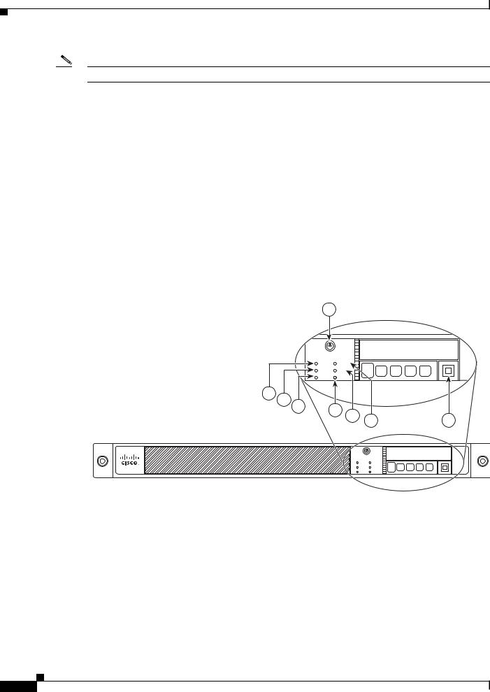
Figure 1-2 shows the front panel LEDs for the ASA 5512-X, ASA 5515-X, and ASA 5525-X models.
Figure 1-2 Front Panel LEDs for the Cisco ASA 5512-X, ASA 5515-X, and ASA 5525-X
1
Cisco ASA 5515 |
|
Adapative Security Appliance |
|
BOOT |
ALARM |
ACTIVE |
VPN |
PS |
|
8 |
7 |
6 |
5 |
4 |
|
|
|
|
|
3 |
2 |
||
|
|
|
|
|||
|
|
|
|
|
Cisco ASA 5515 |
|
Adapative Security Appliance |
|
BOOT |
ALARM |
ACTIVE |
VPN |
PS |
HD |
282360
|
LED |
Description |
|
|
|
1 |
Power button |
A soft switch that turns the system on and off. Once depressed, the |
|
|
button stays in the “on” position: |
|
|
• On—The power symbol on the button illuminates. |
|
|
• Off—The power symbol on the button is dark. |
|
|
For information about the power state, see the “Power Supply |
|
|
Considerations” section on page 2-4. |
|
|
|
2 |
Hard disk release button |
Releases the hard disk from the device. |
|
|
|
Cisco ASA 5500-X Series Hardware Installation Guide
1-6
Chapter 1 Information about the ASA 5500-X
ASA Chassis Panels
3 |
Alarm |
Indicates system operating status: |
|
|
• Off—Normal operating system function. |
|
|
• Flashing amber—Critical Alarm indicating one or more of the |
|
|
following: |
|
|
– a major failure of a hardware or software component. |
|
|
– an over-temperature condition. |
|
|
– power voltage is outside of the tolerance range. |
|
|
|
4 |
VPN |
Indicates VPN tunnel status: |
|
|
• Solid green—VPN tunnel is established. |
|
|
• Off—No VPN tunnel is established. |
|
|
|
5 |
HD |
Indicates Hard Disk Drive status: |
|
|
• Flashing green—Proportioned to read/write activity. |
|
|
• Solid amber—Hard disk drive failure. |
|
|
• Off—No hard disk drive present. |
|
|
|
6 |
PS |
Indicates the power supply status |
|
|
|
7 |
Active |
Indicates the status of the failover pair: |
|
|
• Solid green—Failover pair is operating normally. |
|
|
• Off—Failover is not operational. |
|
|
|
8 |
Boot |
Indicates power-up diagnostics: |
|
|
• Flashing green—Power-up diagnostics are running, or system |
|
|
is booting. |
|
|
• Solid green—System has passed power-up diagnostics. |
|
|
• Off—Power-up diagnostics are not operational. |
|
|
|
Figure 1-3 shows the front panel LEDs for the ASA 5545-X and ASA 5555-X models.
Cisco ASA 5500-X Series Hardware Installation Guide
1-7

Chapter 1 Information about the ASA 5500-X
ASA Chassis Panels
Figure 1-3 Front Panel LEDs for Cisco ASA 5545-X and ASA 5555-X
1 |
2 |
3 |
Cisco ASA 5545 |
1 |
|
Adapative Security Appliance |
||
BOOT |
ALARM |
|
ACTIVE |
VPN |
|
PS1 |
HD1 |
|
PS0 |
HD0 |
0 |
13 12 11 |
10 |
9 |
|
8 |
6 |
5 |
4 |
7
Cisco ASA 5545 |
1 |
|
Adapative Security Appliance |
||
BOOT |
ALARM |
|
ACTIVE |
VPN |
|
PS1 |
HD1 |
|
PS0 |
HD0 |
0 |
|
|
282359 |
|
|
|
|
LED |
Description |
|
|
|
1 |
Power button |
A soft switch that turns the system on and off. Once depressed, the |
|
|
button stays in the “on” position: |
|
|
• On—The power symbol on the button illuminates. |
|
|
• Off—The power symbol on the button is dark. |
|
|
For information about the power state, see the “Power Supply |
|
|
Considerations” section on page 2-4. |
|
|
|
2 |
Hard disk slot |
Indicates the slot for hard disk 1. |
|
|
|
3 |
Hard disk release button |
Releases hard disk 1 from the device. |
|
|
|
4 |
Hard disk release button |
Releases hard disk 0 from the device. |
|
|
|
5 |
Hard disk slot |
Indicates the slot for hard disk 0. |
|
|
|
6 |
Alarm |
Indicates system operating status: |
|
|
• Off—Normal operating system function |
|
|
• Flashing amber—Critical Alarm indicating one or more of the |
|
|
following: |
|
|
– a major failure of a hardware or software component. |
|
|
– an over-temperature condition. |
|
|
– power voltage is outside of the tolerance range. |
|
|
|
7 |
VPN |
Indicates VPN tunnel status: |
|
|
• Solid green—VPN tunnel is established. |
|
|
• Off—No VPN tunnel is established. |
|
|
|
Cisco ASA 5500-X Series Hardware Installation Guide
1-8

Chapter 1 Information about the ASA 5500-X
ASA Chassis Panels
8 |
HD1 |
Indicates Hard Disk Drive 1 status: |
|
|
• Flashing green—Proportioned to read/write activity. |
|
|
• Solid amber—Hard disk drive failure. |
|
|
• Off—No hard disk drive present. |
|
|
|
9 |
HD0 |
Indicates Hard Disk Drive 0 status: |
|
|
• Flashing green—Proportioned to read/write activity. |
|
|
• Solid amber—Hard disk drive failure. |
|
|
• Off—No hard disk drive present. |
|
|
|
10 |
PS1 |
Indicates the status of the optional redundant power supply. |
|
|
|
11 |
PS0 |
Indicates the status of the primary power supply that ships with the |
|
|
product. |
|
|
|
12 |
Active |
Indicates the status of the failover pair: |
|
|
• Solid green—Failover pair is operating normally. |
|
|
• Off—Failover pair is not operational. |
|
|
|
13 |
Boot |
Indicates power-up diagnostics: |
|
|
• Flashing green—Power-up diagnostics are running, or system |
|
|
is booting. |
|
|
• Solid green—System has passed power-up diagnostics. |
|
|
• Off—Power-up diagnostics are not operational. |
|
|
|
Rear Panel LEDs
Figure 1-4 shows the rear panel LEDs for the ASA 5500-X series chassis.
Figure 1-4 Rear Panel LEDs for ASA 5500-X Series Chassis
1 |
3 |
5 |
7 |
2 4 6
332118
Cisco ASA 5500-X Series Hardware Installation Guide
1-9

Chapter 1 Information about the ASA 5500-X
ASA Chassis Panels
|
LED |
Description |
|
|
|
1 |
Power |
Indicates power supply status: |
|
|
• Off—Power supply off. |
|
|
• Solid green—Power supply on. |
|
|
|
2 |
Alarm |
Indicates system operating status: |
|
|
• Off—Normal operating system function |
|
|
• Flashing amber—Critical Alarm indicating one or more of the |
|
|
following: |
|
|
– a major failure of a hardware or software component. |
|
|
– an over-temperature condition. |
|
|
– power voltage is outside of the tolerance range. |
|
|
|
3 |
Boot |
Indicates power-up diagnostics: |
|
|
• Flashing green—Power-up diagnostics are running, or system |
|
|
is booting. |
|
|
• Solid green—System has passed power-up diagnostics. |
|
|
• Off—Power-up diagnostics are not operational. |
|
|
|
4 |
Active |
Indicates the status of the failover pair: |
|
|
• Solid green—Failover pair is operating normally. |
|
|
• Off—Failover pair is not operational. |
|
|
|
5 |
VPN |
Indicates VPN tunnel status: |
|
|
• Solid green—VPN tunnel is established. |
|
|
• Off—No VPN tunnel is established. |
|
|
|
6 |
HD0 |
Indicates Hard Disk Drive 0 status: |
|
|
• Flashing green—Proportioned to read/write activity. |
|
|
• Solid amber—Hard disk drive failure. |
|
|
• Off—No hard disk drive present. |
|
|
|
7 |
HD1 |
Indicates Hard Disk Drive 1 status: |
|
|
• Flashing green—Proportioned to read/write activity. |
|
|
• Solid amber—Hard disk drive failure. |
|
|
• Off—No hard disk drive present. |
|
|
|
Cisco ASA 5500-X Series Hardware Installation Guide
1-10
Loading...