


C H A P T E R 4
Configuring Interfaces
This chapter describes basic interface configurations for your Layer 3 switch router. Also included are sections about configuring virtual LANs (VLANs), packet-over-SONET interfaces, ATM uplink interfaces, and port snooping.
Unless otherwise noted, the information in this chapter applies to the Catalyst 8540 CSR,
Catalyst 8510 CSR, and Catalyst 8540 MSR with Layer 3 functionality. For further information about the commands used in this chapter, refer to the command reference publications in the Cisco IOS documentation set and to Appendix A, “Command Reference.”
This chapter includes the following sections:
•Overview of Interface Configuration
•General Instructions for Configuring Interfaces
•About Layer 3 Switching Interfaces
•About Virtual LANs
•Configuring ISL VLAN Encapsulation
•Configuring 802.1Q VLAN Encapsulation
•About Packet over SONET (Catalyst 8540)
•Configuring the POS OC-12c Uplink Interface (Catalyst 8540)
•About ATM Uplinks (Catalyst 8540)
•Configuring the ATM Uplink Interface (Catalyst 8540)
•About Port Snooping
•Configuring Snooping
Note You are at Step 3 in the suggested process for configuring your switch router (see the “Suggested Procedure for Configuring Your Switch Router” section on page 2-1). You should have already configured the processor module (and LAN emulation on the Catalyst 8540 MSR) and now be ready to proceed with configuring interfaces.
|
|
Layer 3 Switching Software Feature and Configuration Guide |
|
|
|
|
|
|
|||
|
78-6235-04, Cisco IOS Release 12.0(10)W5(18) |
|
|
4-1 |
|
|
|
|
|

Chapter 4 Configuring Interfaces
Overview of Interface Configuration
Overview of Interface Configuration
A router’s main function is to relay packets from one data link to another. To do that, the characteristics of the interfaces through which the packets are received and sent must be defined. Interface characteristics include, but are not limited to, IP address, address of the port, data encapsulation method, and media type.
Many features are enabled on a per-interface basis. Interface configuration mode contains commands that modify the interface operation, for example, of an Ethernet port. When you issue the interface command, you must define the interface type and number.
The following general guidelines apply to all physical and virtual interface configuration processes.
•Each interface must be configured with an IP address and an IP subnet mask.
•The virtual interfaces supported by Cisco switch routers include subinterfaces and IP tunnels.
A subinterface is a mechanism that allows a single physical interface to support multiple logical interfaces or networks—that is, several logical interfaces or networks can be associated with a single hardware interface. Configuring multiple virtual interfaces, or subinterfaces, on a single physical interface allows greater flexibility and connectivity on the network.
Layer 3 interfaces have both a Media Access Control (MAC) address and an interface port ID. The router keeps track of these designators and uses them to route traffic.
Media Access Control Address
The MAC address, also referred to as the hardware address, is required for every port or device that connects to a network. Other devices in the network use MAC addresses to locate specific ports in the network and to create and update routing tables and data structures.
Tips To find the MAC address for a device, use the show interfaces command.
Interface Port Identifier
The interface port identifier designates the physical location of the Layer 3 interface within the chassis. This is the name that you use to identify the interface when configuring it. The system software uses interface port identifiers to control activity within the switch router and to display status information. Interface port identifiers are not used by other devices in the network; they are specific to the individual switch router and its internal components and software.
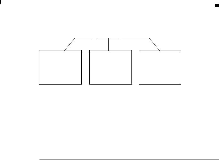
You can find the interface port identifier on the rear of the switch router. It is composed of three parts, formatted as slot/subslot/interface as depicted in Figure 4-1.
|
Layer 3 Switching Software Feature and Configuration Guide |
4-2 |
78-6235-04, Cisco IOS Release 12.0(10)W5(18) |
Chapter 4 Configuring Interfaces
General Instructions for Configuring Interfaces
Figure 4-1 Interface Port Identifier Format
slot number / subslot number / interface number
The slot in which the interface module or port adapter is installed. Slots are numbered starting at 0.
The subslot in which the interface module or port adapter is installed. For a full-width interface module, this number is always 0.
The port or interface number on the interface module or port adapter. Numbering always starts at 0 and goes from left to right.

 27934
27934
The interface port identifiers on the Ethernet modules remain the same regardless of whether other modules are installed or removed. However, when you move an interface module to a different slot, the first number in the address changes to reflect the new slot number.
You can identify module ports by physically checking the slot/subslot/interface location on the back of the switch router. You can also use Cisco IOS show commands to display information about a specific interface, or all the interfaces, in the switch router.
General Instructions for Configuring Interfaces
The following general configuration instructions apply to all interfaces. Begin in global configuration mode. To configure an interface, follow these steps:
Step 1 Use the configure EXEC command at the privileged EXEC prompt to enter the global configuration mode.
Router> enable
Router# configure terminal
Router (config)#
Step 2 Enter the interface command, followed by the interface type (for example, Fast Ethernet or Gigabit Ethernet) and its interface port identifier (see the “Interface Port Identifier” section on page 4-2).
For example, to configure the Gigabit Ethernet port on slot 1, port 1, use this command:
Router(config)# interface gigabitethernet 1/0/1
|
|
Layer 3 Switching Software Feature and Configuration Guide |
|
|
|
|
|
|
|||
|
78-6235-04, Cisco IOS Release 12.0(10)W5(18) |
|
|
4-3 |
|
|
|
|
|

Chapter 4 Configuring Interfaces
About Layer 3 Switching Interfaces
Step 3 Follow each interface command with the interface configuration commands required for your particular interface.
The commands you enter define the protocols and applications that will run on the interface. The commands are collected and applied to the interface command until you enter another interface command, a command that is not an interface configuration command, or you enter end to return to privileged EXEC mode.
Step 4 Check the status of the configured interface by using the EXEC show commands.
Router# show interface gigabitethernet 1/0/1
GigabitEthernet1/0/1 is up, line protocol is up
Hardware is K1 Gigabit Port, address is 00d0.ba1d.3207 (bia 00d0.ba1d.3207) MTU 1500 bytes, BW 1000000 Kbit, DLY 10 usec, rely 255/255, load 1/255 Encapsulation ARPA, loopback not set, keepalive set (10 sec)
Full-duplex mode, 1000Mb/s, Auto-negotiation, 1000BaseSX
output flow-control is unsupported, input flow-control is unsupported ARP type: ARPA, ARP Timeout 04:00:00
About Layer 3 Switching Interfaces
Layer 3 switching supports two different Gigabit Ethernet interfaces, an eight-port module and a two-port module. This section describes the initial configurations for both interface types.
Tips Before you configure interfaces, be sure to have the interface network (IP or IPX) addresses and the corresponding subnet mask information. If you do not have this information, consult your network administrator.
The Gigabit Ethernet interface modules can be configured as trunk ports, non-trunking ports, routed ports, or bridged ports. The trunk ports employ 802.1Q encapsulation; Inter-Switch Link (ISL) is not supported. You can use the Gigabit Ethernet ports as routed interfaces, or you can configure the ports into a bridge group, which is the recommended configuration.
By configuring as many ports as possible in a bridge group, you can optimize the throughput of your switch router. You can also ensure that your networks are routed by using integrated routing and bridging features from Cisco IOS software. For configuration instructions, see the “About Integrated Routing and Bridging” section on page 6-4.
Between ports on the eight-port Gigabit Ethernet interface module itself, local switching at Layer 2 provides nonblocking performance at wire speed. For ports on this module configured as a bridge group, Layer 2 traffic is processed at full Gigabit Ethernet rates. For Layer 3 traffic, however, this interface module provides 2-Gbps routing bandwidth from the switch fabric.
|
Layer 3 Switching Software Feature and Configuration Guide |
4-4 |
78-6235-04, Cisco IOS Release 12.0(10)W5(18) |

Chapter 4 Configuring Interfaces
About Layer 3 Switching Interfaces
Initially Configuring Gigabit Ethernet Interfaces
To configure an IP address and autonegotiation on a Gigabit Ethernet interface, perform the following steps, beginning in global configuration mode:
|
Command |
Purpose |
Step 1 |
|
|
Router(config)# interface gigabitethernet |
Enters Ethernet interface configuration mode to |
|
|
slot/subslot/interface |
configure the Gigabit Ethernet interface. |
|
Router(config-if)# |
|
Step 2 |
|
|
Router(config-if)# [no] negotiation auto |
Specifies the negotiation mode. |
|
|
|
When you set negotiation mode to auto, the |
|
|
Gigabit Ethernet port attempts to negotiate the |
|
|
link (that is, both port speed and duplex setting) |
|
|
with the partner port. |
|
|
When you set the Gigabit Ethernet interface to no |
|
|
negotiation auto, the port forces the link up no |
|
|
matter what the partner port setting is. This brings |
|
|
up the link with 1000 Mbps and full duplex only. |
Step 3 |
|
|
Router(config-if)# ip address ip-address |
Specifies the IP address and IP subnet mask to be |
|
|
subnet-mask |
assigned to the Gigabit Ethernet interface. |
Step 4 |
|
|
Router(config-if)# exit |
Returns to global configuration mode. Repeat |
|
|
Router(config)# |
Steps 1 to 3 to configure another Gigabit Ethernet |
|
interface on this interface module. |
|
|
|
|
Step 5 |
|
|
Router(config)# end |
Returns to privileged EXEC mode. |
|
Step 6 |
|
|
Router# copy system:running-config |
Saves your configuration changes to NVRAM. |
|
|
nvram:startup-config |
|
|
|
|
Example
The following example demonstrates initially configuring a Gigabit Ethernet interface with autonegotiation and an IP address:
Router(config)# interface gigabitethernet 0/0/0
Router(config-if)# negotiation auto
Router(config-if)# ip address 10.1.2.3 255.0.0.0
Router(config-if)# exit
Router(config)# ^Z
C8540-CSR# copy system:running-config nvram:startup-config
About the Enhanced Gigabit Ethernet Interfaces (Catalyst 8540)
The enhanced Gigabit Ethernet interface module provides two Gigabit Ethernet interfaces with built-in ACL support; no daughter card is required. The POS OC-12c uplink interface module and the ATM uplink interface module also include a single enhanced Gigabit Ethernet interface. See “Configuring the POS OC-12c Uplink Interface (Catalyst 8540)” section on page 4-14” and “Configuring the ATM Uplink Interface (Catalyst 8540)” section on page 4-28.
There is no special configuration required for the enhanced Gigabit Ethernet interfaces other than that used for other Gigabit Ethernet interfaces.
|
|
Layer 3 Switching Software Feature and Configuration Guide |
|
|
|
|
|
|
|||
|
78-6235-04, Cisco IOS Release 12.0(10)W5(18) |
|
|
4-5 |
|
|
|
|
|

Chapter 4 Configuring Interfaces
About Layer 3 Switching Interfaces
Initially Configuring Fast Ethernet Interfaces
Use the following procedure to assign an IP address to the Fast Ethernet 10BaseT or 100BaseT interface of your switch router so that it can be recognized as a device on the Ethernet LAN. The Fast Ethernet interface supports 10-Mbps and 100-Mbps speeds with Cisco 10BaseT and 100BaseT routers, hubs, switches, and switch routers.
|
Command |
Description |
Step 1 |
|
|
Router(config)# interface fastethernet |
Enters Ethernet interface configuration mode to |
|
|
slot/subslot/interface |
configure the Fast Ethernet interfaces. |
|
Router(config-if)# |
|
Step 2 |
|
|
Router(config-if)# ip address ip-address |
Specifies the IP address and IP subnet mask to be |
|
|
subnet-mask |
assigned to the FastEthernet interface. |
Step 3 |
|
|
Router(config-if)# [no] speed [10 | 100 | auto] |
Configures the transmission speed for 10 or |
|
|
|
100 Mbps, or for autonegotiation (the default). If |
|
|
you set the speed to auto, you enable |
|
|
autonegotiation, and the switch router matches |
|
|
the speed of the partner node. |
Step 4 |
|
|
Router(config-if)# [no] duplex [full | half | auto] |
Configures for full or half duplex. If you set |
|
|
|
duplex for auto, the switch router matches the |
|
|
duplex setting of the partner node. |
Step 5 |
|
|
Router(config-if)# end |
Returns to privileged EXEC mode. |
|
|
Router# |
|
Step 6 |
|
|
Router# copy system:running-config |
Saves your configuration changes to NVRAM. |
|
|
nvram:startup-config |
|
|
|
|
Example
The following example demonstrates initially configuring a Fast Ethernet interface with an IP address and autonegotiated speed and duplex:
Router(config)# interface fastethernet 1/0/0
Router(config-if)# ip address 10.1.2.4 255.0.0.0
Router(config-if)# speed auto
Router(config-if)# duplex auto
Router(config-if)# ^Z
Router# copy system:running-config nvram:startup-config
Verifying the Ethernet Interface Configuration
To verify the settings after you have configured Gigabit Ethernet or Ethernet 10/100 BaseT operation, use the following commands:
|
|
|
|
Command |
Purpose |
|
|
|
|
|
|
|
|
|
|
|
|
show interface gigabitethernet |
Displays the status and global parameters of the |
|
|
|
|
|
slot/subslot/interface |
Gigabit Ethernet interface. |
|
|
|
|
|
|
|
|
|
|
|
|
show interface fastethernet |
Displays the status and global parameters of the |
|
|
|
|
|
slot/subslot/interface |
Fast Ethernet interface. |
|
|
|
|
|
|
|
|
|
|
|
Layer 3 Switching Software Feature and Configuration Guide |
|
|
|
|
|
|
|
|
||
|
4-6 |
|
|
|
78-6235-04, Cisco IOS Release 12.0(10)W5(18) |
|
|
|
|
|
|
||

Chapter 4 Configuring Interfaces
About Layer 3 Switching Interfaces
Examples
The following example shows sample output from the show interface gigabitethernet command:
Router# show interface gigabitethernet 0/0/0
GigabitEthernet0/0/0 is administratively down, line protocol is down
Hardware is K1 Gigabit Port, address is 00d0.ba1d.3207 (bia 00d0.ba1d.3207) Internet address is 10.1.2.3/8
MTU 1500 bytes, BW 1000000 Kbit, DLY 10 usec, rely 255/255, load 1/255 Encapsulation ARPA, loopback not set, keepalive set (10 sec) Full-duplex mode, 1000Mb/s, Auto-negotiation, 1000BaseSX
output flow-control is unsupported, input flow-control is unsupported ARP type: ARPA, ARP Timeout 04:00:00
Last input never, output never, output hang never Last clearing of "show interface" counters never Queueing strategy: fifo
Output queue 0/40, 0 drops; input queue 0/75, 0 drops 5 minute input rate 0 bits/sec, 0 packets/sec
5 minute output rate 0 bits/sec, 0 packets/sec
0 packets input, 0 bytes, 0 no buffer
Received 0 broadcasts, 0 runts, 0 giants, 0 throttles
0 input errors, 0 CRC, 0 frame, 0 overrun, 0 ignored, 0 abort 0 watchdog, 0 multicast
0 input packets with dribble condition detected
0 packets output, 0 bytes, 0 underruns(0/0/0)
0 output errors, 0 collisions, 0 interface resets
0 babbles, 0 late collision, 0 deferred
0 lost carrier, 0 no carrier
0 output buffer failures, 0 output buffers swapped out
The following example shows sample output from the show interface fastethernet command:
Router# show interface fastethernet 1/0/0
FastEthernet1/0/0 is administratively down, line protocol is down Hardware is epif_port, address is 0010.073c.050f (bia 0010.073c.050f) Internet address is 10.1.2.4/8
MTU 1500 bytes, BW 100000 Kbit, DLY 100 usec, rely 255/255, load 1/255 Encapsulation ARPA, loopback not set, keepalive set (10 sec) Auto-duplex, Auto Speed, 100BaseTX
ARP type: ARPA, ARP Timeout 04:00:00
Last input never, output never, output hang never Last clearing of "show interface" counters never Queueing strategy: fifo
Output queue 0/40, 0 drops; input queue 0/75, 0 drops 5 minute input rate 0 bits/sec, 0 packets/sec
5 minute output rate 0 bits/sec, 0 packets/sec
0 packets input, 0 bytes
Received 0 broadcasts, 0 runts, 0 giants, 0 throttles
0 input errors, 0 CRC, 0 frame, 0 overrun, 0 ignored, 0 abort 0 watchdog, 0 multicast
0 input packets with dribble condition detected
0 packets output, 0 bytes, 0 underruns
0 output errors, 0 collisions, 0 interface resets
0 babbles, 0 late collision, 0 deferred
0 lost carrier, 0 no carrier
0 output buffer failures, 0 output buffers swapped out
|
|
Layer 3 Switching Software Feature and Configuration Guide |
|
|
|
|
|
|
|||
|
78-6235-04, Cisco IOS Release 12.0(10)W5(18) |
|
|
4-7 |
|
|
|
|
|

Chapter 4 Configuring Interfaces
About Virtual LANs
About Virtual LANs
Virtual LANs enable network managers to group users logically rather than by physical location. A virtual LAN (VLAN) is an emulation of a standard LAN that allows data transfer and communication to occur without the traditional restraints placed on the network. It can also be considered a broadcast domain set up within a switch. With VLANs, switches can support more than one subnet (or VLAN) on each switch, and give routers and switches the opportunity to support multiple subnets on a single physical link. A group of devices on a LAN are configured so that they communicate as if they were attached to the same LAN segment, when they are actually located on different segments. Layer 3 switching supports up to 255 VLANs per system.
VLANs enable efficient traffic separation and provide excellent bandwidth utilization. VLANs also alleviate scaling issues by logically segmenting the physical LAN structure into different subnetworks so that packets are switched only between ports within the same VLAN. This can be very useful for security, broadcast containment, and accounting.
Layer 3 switching software supports a port-based VLAN on a trunk port, which is a port that carries the traffic of multiple VLANs. Each frame transmitted on a trunk link is tagged as belonging to only one VLAN.
Layer 3 switching software supports VLAN frame encapsulation through the Inter-Switch Link (ISL) protocol and the 802.1Q standard.
Note The four adjacent ports (such as 0 through 3, or 4 through 7) on a 10/100 interface must all use the same VLAN encapsulation; that is, either 802.1Q and native, or ISL and native.
Configuring ISL VLAN Encapsulation
ISL is a Cisco protocol for interconnecting multiple switches and maintaining VLAN information as traffic travels between switches.
The VLAN configuration example shown in Figure 4-2 depicts the following:
•Fast Ethernet port 1/0/0 and subinterface 1/0/1.1 on the switch router are in bridge group 1. They are part of VLAN 50, which uses ISL encapsulation.
•Fast Ethernet port 3/0/1 and subinterface 1/0/1.2 are in bridge group 2. They are part of VLAN 100, which uses ISL encapsulation.
•Fast Ethernet port 1/0/1 is configured as an ISL trunk.
|
Layer 3 Switching Software Feature and Configuration Guide |
4-8 |
78-6235-04, Cisco IOS Release 12.0(10)W5(18) |
Chapter 4 Configuring Interfaces
Configuring ISL VLAN Encapsulation
Figure 4-2 Example of an ISL VLAN Bridging Configuration
Bridge-group 1
1/0/1.1
|
1/0/0 |
VLAN 50 |
|
|
|
|
|
|
|
encap isl 50 |
|
Campus |
|
encap isl 100 |
Campus |
switch |
|
|
switch |
router |
|
|
router |
VLAN 100
3/0/1 1/0/1.2 Bridge-group 2
17489
To configure the Layer 3 VLANs shown in Figure 4-2, perform the following steps, beginning in global
|
configuration mode: |
|
|
|
|
|
|
|
|
|
|||
|
Command |
|
Purpose |
|
||
Step 1 |
|
|
|
|
||
Router(config)# interface fastethernet |
|
Enters subinterface configuration mode. |
|
|||
|
slot/subslot/interface.subinterface |
|
|
|
|
|
|
Router(config-subif)# |
|
|
|
|
|
Step 2 |
|
|
|
|
||
Router(config-subif)# encapsulation isl vlan-id |
|
Specifies ISL encapsulation for the Ethernet |
|
|||
|
|
|
frames sent from this subinterface with a |
|
||
|
|
|
header that maintains the specified VLAN ID |
|
||
|
|
|
between network nodes. |
|
||
Step 3 |
|
|
|
|
||
Router(config-subif)# bridge-group bridge-group |
|
Assigns the subinterface a bridge group |
|
|||
|
|
|
number. |
|
||
|
|
|
|
|
|
|
|
|
|
Note |
When you are configuring VLAN |
|
|
|
|
|
|
|
routing, skip this step. |
|
Step 4 |
|
|
|
|
|
|
|
|
|
|
|||
Router(config-subif)# interface fastethernet |
|
Enters interface configuration mode to |
|
|||
|
slot/subslot/interface |
|
configure the Fast Ethernet main interface. |
|
||
|
Router(config-if)# |
|
|
|
|
|
Step 5 |
|
|
|
|
||
Router(config-if)# bridge-group bridge-group |
|
Assigns the main interface to the bridge |
|
|||
|
|
|
group. |
|
|
|
Step 6 |
|
|
|
|
||
Router(config-if)# exit |
|
Returns to global configuration mode. |
|
|||
|
Router(config)# |
|
|
|
|
|
Step 7 |
|
|
|
|
||
Router(config)# bridge bridge-group protocol ieee |
|
Specifies that the bridge group will use the |
|
|||
|
|
|
IEEE Ethernet Spanning Tree Protocol. |
|
||
|
|
|
|
|
|
|
|
|
Layer 3 Switching Software Feature and Configuration Guide |
|
|
|
|
|
|
|||
|
78-6235-04, Cisco IOS Release 12.0(10)W5(18) |
|
|
4-9 |
|
|
|
|
|

Chapter 4 Configuring Interfaces
Configuring 802.1Q VLAN Encapsulation
Example
The following example shows how to configure the interfaces for VLAN bridging with ISL encapsulation shown in Figure 4-2:
Router(config)# interface fastethernet 1/0/1.1
Router(config-subif)# encap isl 50
Router(config-subif)# bridge-group 1
Router(config-subif)# interface fastethernet 1/0/0
Router(config-if)# bridge-group 1
Router(config-if)# exit
Router(config)# bridge 1 protocol ieee
Router(config)# interface fastethernet 1/0/1.2
Router(config-subif)# encap isl 100
Router(config-subif)# bridge-group 2
Router(config-subif)# interface fastethernet 3/0/1
Router(config-subif)# bridge-group 2
Router(config-subif)# exit
Router(config)# bridge 2 protocol ieee
Router(config)# exit
Router# copy system:running-config nvram:startup-config
When configuring ISL with IP, you cannot configure IP addresses on a subinterface unless the VLANs are already configured (that is, you must have already entered the encapsulation isl or encapsulation dot1q command). That is not the case with IPX, however—you can configure IPX networks on a subinterface even when the VLANs have not been configured.
The maximum VLAN bridge group values are as follows:
•Maximum number of bridge groups: 64
•Maximum number of interfaces per bridge group: 128
•Maximum number of subinterfaces per system: 255
For a complete configuration example for VLANs with ISL encapsulation, see the “Catalyst 8540 CSR with ISL, VLAN, and BVI with GEC” section on page C-1.
To monitor the VLANs once they are configured, use the commands described in the “Monitoring VLAN Operation” section on page 4-12.
Configuring 802.1Q VLAN Encapsulation
The IEEE 802.1Q standard provides a method for secure bridging of data across a shared backbone. IEEE 802.1Q VLAN encapsulation uses an internal, or one level, packet tagging scheme to multiplex VLANs across a single physical link, while maintaining strict adherence to the individual VLAN domains.
On an IEEE 802.1Q trunk port, all transmitted and received frames are tagged except for those on the one VLAN configured as the PVID (port VLAN identifier) or native VLAN for the port. Frames on the native VLAN are always transmitted untagged and are normally received untagged.
The VLAN configuration example shown in Figure 4-3 depicts the following:
•Fast Ethernet ports 1/0/0 and subinterface 1/0/1.1 on the switch router are in bridge group 1. They are part of native VLAN 1, which uses 802.1Q encapsulation.
•Fast Ethernet port 3/0/1 and subinterface 1/0/1.2 are in bridge group 2. They are part of VLAN 100, which uses 802.1Q encapsulation.
•Fast Ethernet port 1/0/1 is configured as an 802.1Q trunk.
|
Layer 3 Switching Software Feature and Configuration Guide |
4-10 |
78-6235-04, Cisco IOS Release 12.0(10)W5(18) |
Chapter 4 Configuring Interfaces
Configuring 802.1Q VLAN Encapsulation
Figure 4-3 Example of Bridging Between Native and Non-Native 802.1Q VLANs
Bridge-group 1
1/0/1.1
|
1/0/0 |
|
|
Native VLAN 1 |
|
|
encap dot1q 1 native |
|
Campus |
encap dot1q 100 |
Campus |
switch |
|
switch |
router |
|
router |
Non-native VLAN 100
3/0/1 1/0/1.2
Bridge-group 2
28089
To configure the bridging between native VLAN 1 and non-native VLAN 100 depicted in Figure 4-3, perform the following steps:
|
Command |
Purpose |
|
|||
Step 1 |
|
|
|
|||
Router(config)# interface fastethernet |
Enters subinterface configuration mode. |
|
||||
|
slot/subslot/interface.subinterface |
|
|
|
|
|
Step 2 |
|
|
|
|||
Router(config-subif)# encap dot1q vlan-id native |
Specifies 802.1Q encapsulation for Ethernet |
|
||||
|
|
frames sent from the subinterface with a header |
|
|||
|
|
that maintains the specified native VLAN ID |
|
|||
|
|
between network nodes. |
|
|||
Step 3 |
|
|
|
|||
Router(config-subif)# bridge-group |
Assigns the subinterface a bridge group number. |
|
||||
|
bridge-group |
|
|
|
|
|
|
|
|
|
|
|
|
|
|
Note |
When you are configuring VLAN |
|
||
|
|
|
|
|
routing, skip this step. |
|
Step 4 |
|
|
|
|
||
|
|
|
||||
Router(config-subif)# interface fastethernet |
Enters interface configuration mode to configure |
|
||||
|
slot/subslot/interface |
the Fast Ethernet main interface. |
|
|||
Step 5 |
|
|
|
|||
Router(config-if)# bridge-group bridge-group |
Assigns the main interface to the bridge group. |
|
||||
Step 6 |
|
|
|
|||
Router(config-if)# exit |
Returns to global configuration mode. |
|
||||
Step 7 |
|
|
|
|||
Router(config)# bridge bridge-group protocol |
Specifies that the bridge group will use the IEEE |
|
||||
|
ieee |
Ethernet Spanning Tree Protocol. |
|
|||
|
|
|
|
|
|
|
|
|
Layer 3 Switching Software Feature and Configuration Guide |
|
|
|
|
|
|
|||
|
78-6235-04, Cisco IOS Release 12.0(10)W5(18) |
|
|
4-11 |
|
|
|
|
|

Chapter 4 Configuring Interfaces
Monitoring VLAN Operation
Example
The following example shows how to configure the bridging between native and non-native 802.1Q VLANs shown in Figure 4-3:
Router(config)# interface fastethernet 1/0/1.1
Router(config-subif)# encap dot1q 1 native
Router(config-subif)# bridge-group 1
Router(config-subif)# interface fastethernet 1/0/0
Router(config-if)# bridge-group 1
Router(config-if)# exit
Router(config)# bridge 1 protocol ieee
Router(config)# interface fastethernet 1/0/1.2
Router(config-subif)# encap dot1q 100
Router(config-subif)# bridge-group 2
Router(config-subif)# interface fastethernet 3/0/1
Router(config-subif)# bridge-group 2
Router(config-subif)# exit
Router(config)# bridge 2 protocol ieee
Router(config)# exit
Router# copy system:running-config nvram:startup-config
Monitoring VLAN Operation
Once the VLANs are configured on the switch router, you can monitor their operation using the following commands:
Command |
Purpose |
|
|
show vlan vlan-id |
Displays information on all configured VLANs or on a specific |
|
VLAN (by VLAN ID number). |
|
|
clear vlan vlan-id |
Clears the counters for all VLANs, when the VLAN ID is not |
|
specified. |
|
|
debug vlan packet |
Displays contents of the packets sent to and exiting from the route |
|
processor. |
|
|
To configure encapsulation over the EtherChannel, see the “About Encapsulation over EtherChannel” section on page 7-6.
About Packet over SONET (Catalyst 8540)
Synchronous Optical Network (SONET) is an octet-synchronous multiplex scheme that defines a family of standard rates and formats. Optical specifications are defined for single-mode fiber and multimode fiber. The transmission rates are integral multiples of 51.840 Mbps. For example, the POS OC-12c uplink interface provides 622.080 Mbps over single-mode optical fiber.
POS provides for the serial transmission of data over SONET frames using either High-Level Data Link Control (HDLC) protocol (the default) or Point-to-Point Protocol (PPP) encapsulation. On serial interfaces, Cisco’s implementation provides error detection and synchronous framing functions of traditional HDLC without the windowing or retransmission that are found in traditional HDLC.
|
Layer 3 Switching Software Feature and Configuration Guide |
4-12 |
78-6235-04, Cisco IOS Release 12.0(10)W5(18) |

Chapter 4 Configuring Interfaces
About the POS OC-12c Uplink Interface
Because SONET/SDH (Synchronous Digital Hierarchy) is by definition a point-to-point circuit, PPP is well suited for use over SONET links. The octet stream is mapped into the SONET/SDH synchronous payload envelope (SPE) in accordance with RFC 2615, “PPP over SONET/SDH,” and RFC 2615, “PPP in HDLC-like Framing.” Octet boundaries are aligned with the SPE octet boundaries, and the PPP frames are located by row within the SPE payload. Because frames are variable in length, the frames can cross SPE boundaries. Using this scheme, multiprotocol data can be encapsulated and transported directly into SONET frames without relying on ATM to provide Layer 2 capability (for example, in IP over ATM over SONET).
About the POS OC-12c Uplink Interface
POS technology is ideally suited for networks that are built for providing Internet or IP data. It provides superior bandwidth utilization and efficiency over other transport methods. For expensive WAN links, POS can provide as much as 25 to 30 percent higher throughput than ATM-based networks.
Transporting frames directly into the SONET/SDH payload eliminates the overhead required in ATM cell header, IP over ATM encapsulation, and segmentation and reassembly (SAR) functionality.
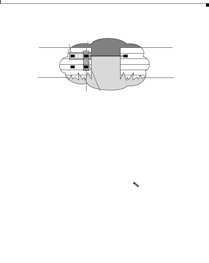
Figure 4-4 shows a typical application of the POS OC-12c uplink interface module in an enterprise setting. Here the enterprise backbone is comprised of POS links among Catalyst 8540 campus switch routers in each building.
Figure 4-4 POS for Enterprise Backbone Connectivity
OC-12c POS |
OC-12c POS |
|
POS |
OC-12c POS |
OC-12c POS |
30746
|
|
Layer 3 Switching Software Feature and Configuration Guide |
|
|
|
|
|
|
|||
|
78-6235-04, Cisco IOS Release 12.0(10)W5(18) |
|
|
4-13 |
|
|
|
|
|
 Loading...