


 Loading...
Installing and Configuring Cisco 802 IDSL and Cisco 804 IDSL Routers
Overview
Cisco 802 IDSL and Cisco 804 IDSL routers offer high-speed digital connections using an ISDN line and support line rates up to 144 kilobits per second (kbps). Integrated Services Digital Network (ISDN) Digital Subscriber Line (IDSL) expands DSL connectivity for customers who are outside the Service Provider’s range for DSL or for those who are unable to qualify for DSL connections.
This document describes the setup and configuration of your routers and contains the following sections:
•Before You Start
•Unpacking the Router
•Connecting Cables to the Router
•Configuring the IDSL Router
Corporate Headquarters:
Cisco Systems, Inc., 170 West Tasman Drive, San Jose, CA 95134-1706 USA
Copyright © 2005 Cisco Systems, Inc. All rights reserved.

Before You Start
The following figure shows a typical setup of the Cisco 804 IDSL router.
Cisco 804 IDSL Router


 Internet Personal

computer
Power supply
Corporate LAN
Personal computer
Personal computer
Personal computer
Before You Start
Before you begin installing your Cisco IDSL router, read the following topics:
•Safety
•Preventing Electrostatic Discharge Damage
•Preventing Router Damage
Safety
Before installing the router, read the following warnings:
.
Warning Only trained and qualified personnel should be allowed to install, replace, or service this equipment.
Statement 1030
Warning Read the installation instructions before connecting the system to the power source. Statement 1004
Installing and Configuring Cisco 802 IDSL and Cisco 804 IDSL Routers
2 |
78-10368-03 |
|
|

Before You Start
Warning Before working on a system that has a standby/off switch, turn off the power by pressing the power switch to standby and unplug the power cord. Statement 150
Warning Before working on equipment that is connected to power lines, remove jewelry (including rings, necklaces, and watches). Metal objects will heat up when connected to power and ground and can cause serious burns or weld the metal object to the terminals. Statement 43
Warning The IDSL connection is regarded as a source of voltage that should be inaccessible to user contact. Do not attempt to tamper with or open any public telephone operator (PTO)-provided equipment or connection hardware. Any hardwired connection (other than by a nonremovable, connect-one-time-only plug) must be made only by PTO staff or suitably trained engineers.
Statement 23
Warning To avoid electric shock, do not connect safety extra-low voltage (SELV) circuits to telephone-network voltage (TNV) circuits. LAN ports contain SELV circuits, and WAN ports contain TNV circuits. Some LAN and WAN ports both use RJ-45 connectors. Use caution when connecting cables. Statement 1021
Warning Ultimate disposal of this product should be handled according to all national laws and regulations.
Statement 1040
Warning If the symbol of suitability with an overlaid cross ( ) appears above a port, you must not connect the port to a public network that follows the European Union standards. Connecting the port to this type of public network can cause severe personal injury or can damage the unit. Statement 1031
Preventing Electrostatic Discharge Damage
Electrostatic discharge (ESD) is a transfer of electrostatic charge between bodies of different electrostatic potentials, such as an operator and a piece of electrical equipment. It occurs when electronic components are improperly handled, and it can damage equipment and impair electrical circuitry. Electrostatic discharge is more likely to occur with the combination of synthetic fibers and dry atmosphere.
Step 1 Always use the following ESD-prevention procedures when removing and replacing components: Connect the chassis to earth ground with a wire that you provide.
Step 2 Wear an ESD-preventive wrist strap that you provide, ensuring that it makes good skin contact.
Connect the clip to an unpainted surface of the chassis frame to safely channel unwanted ESD voltages to ground. To properly guard against ESD damage and shocks, the wrist strap and cord must operate effectively. If no wrist strap is available, ground yourself by touching the metal part of the chassis. Always follow the guidelines in the preceding section, “Safety.”
Step 3 Do not touch any exposed contact pins or connector shells of interface ports that do not have a cable attached.
Installing and Configuring Cisco 802 IDSL and Cisco 804 IDSL Routers
|
78-10368-03 |
3 |
|
|
|
Unpacking the Router
If cables are connected at one end only, do not touch the exposed pins at the unconnected end of the cable.
Note This device is intended for use in residential and commercial environments only.
Caution Periodically check the resistance value of the antistatic strap, which should be between 1 and 10 megohms (Mohms).
Preventing Router Damage
Use the following guidelines when connecting devices to your router:
•Connect the color-coded cables supplied by Cisco to the color-coded ports on the back panel.
•If the symbol of suitability ( ) appears above a port, you can connect the port directly to a public network that follows the European Union standards.
Warning If the symbol of suitability with an overlaid cross appears above a port, you must not connect the port to a public network that follows the European Union standards. Connecting the port to this type of public network can cause severe personal injury or can damage the unit. Statement 1031
Unpacking the Router
Your router package should include the following items:
•Ethernet cable (yellow)
•IDSL cable (red)
•RJ-45 to RJ-11 adapter cable (for use with red IDSL cable)
•Desktop power supply
•Power cord (black)
•Console cable (light blue)
•DB-9 to RJ-45 adapter (for use with light blue console cable)
•Product documentation
Installing and Configuring Cisco 802 IDSL and Cisco 804 IDSL Routers
4 |
78-10368-03 |
|
|
Connecting Cables to the Router
Connecting Cables to the Router
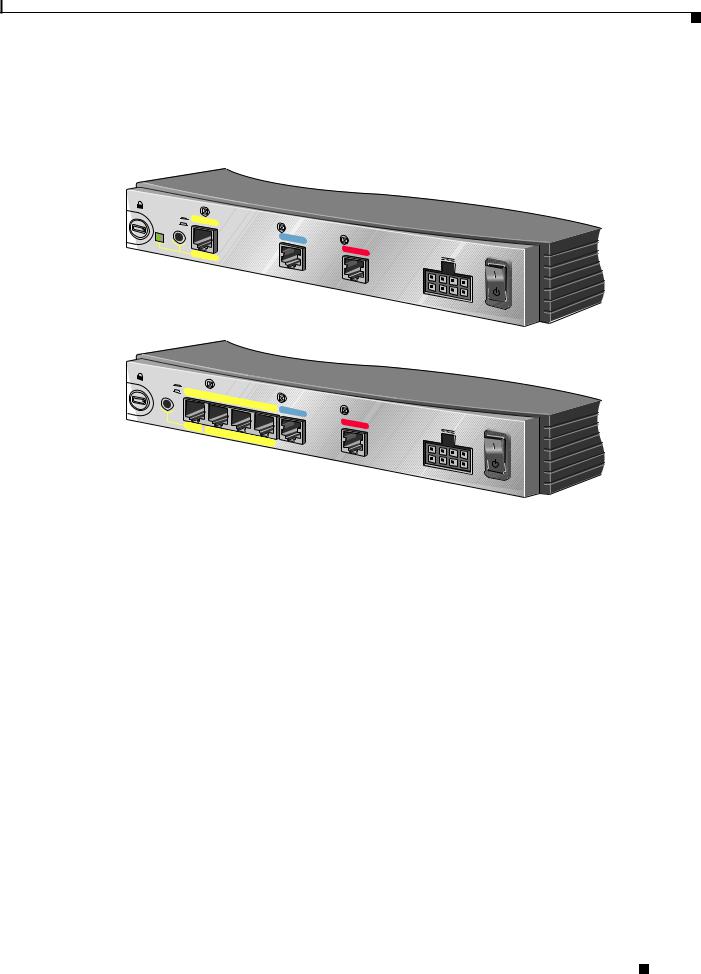
The following figures show the router ports. These ports and the cables are color-coded to help you connect the cables correctly.
TO HUB
TO PC
LINK
ETHERNET
10BASE T
Cisco |
|
|
802 |
IDSL |
|
CONSOLE |
||
|
IDSL |
+5, - |
|
|
24, -71 |
VDC |
|
|
Cisco 802 IDSL Router
TO HUB
TO PC
ETHERNET 10 |
BASE T |
|
|
1 |
|
2 |
3 |
|
Cisco |
|
|
804 |
IDSL |
|
CONSOLE |
||
|
IDSL |
+5, - |
|
|
24, -71 |
VDC |
4
Cisco 804 IDSL Router
For more information, see the following subsections:
•Connecting an Ethernet Device
•Connecting a Hub
•Connecting a Server, PC, or Workstation
•Connecting an IDSL Line
•Connecting the Power Supply
•Verifying Router Connections
Installing and Configuring Cisco 802 IDSL and Cisco 804 IDSL Routers
|
78-10368-03 |
5 |
|
|
|
Connecting Cables to the Router
Connecting an Ethernet Device
This section describes how to connect a hub, server, PC, or workstation with a 10or 10/100-Mbps network interface card (NIC).
Before connecting an Ethernet device, you need to know the following:
•Cisco provides one yellow cable to connect an Ethernet device. If you want to connect more than one device, you must provide additional straight-through cables. See the Cisco 800 Series Routers Hardware Installation Guide for straight-through cable specifications.
•The TO HUB/TO PC button corresponds to the Ethernet port on Cisco 802 IDSL routers and to Ethernet port 1 on Cisco 804 IDSL routers.
Caution Always connect the yellow cable or Ethernet cable to the yellow ports on the router. Do not connect the cable to an IDSL port or to a Network Termination 1 (NT1) device. Accidently connecting the cable to the wrong port can damage your router.
Installing and Configuring Cisco 802 IDSL and Cisco 804 IDSL Routers
6 |
78-10368-03 |
|
|
Connecting Cables to the Router
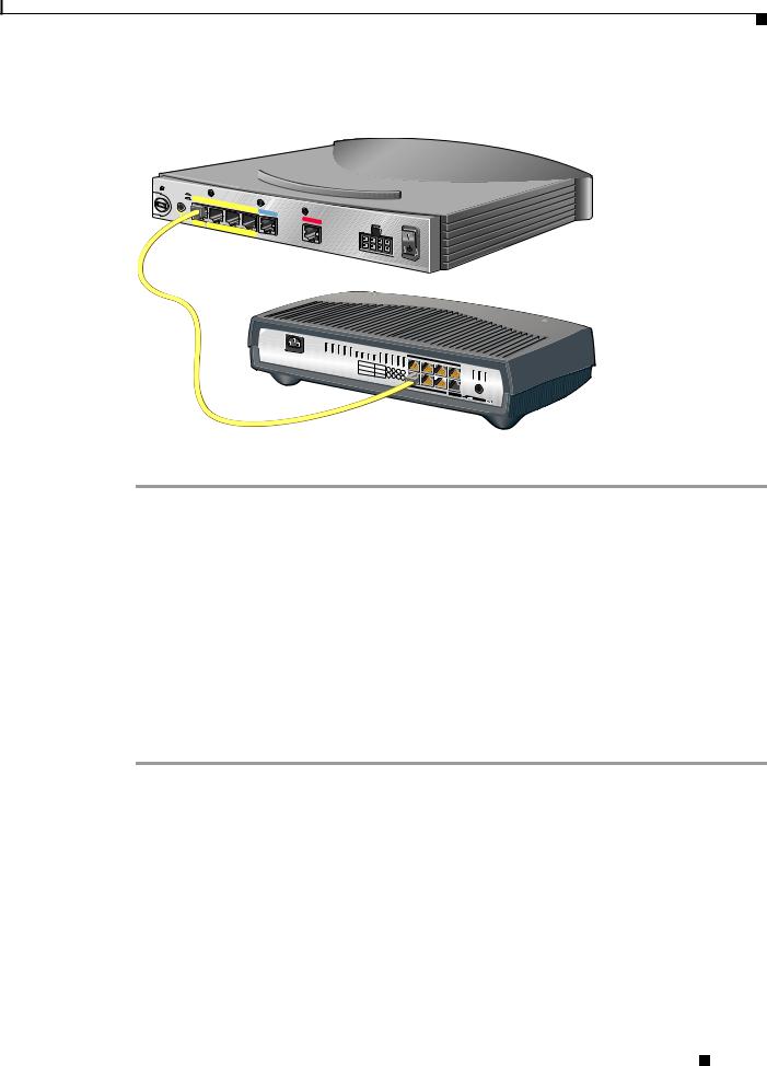
Connecting a Hub
TO HUB
TO PC
ETHERNET 10 |
BASE T |
|
Cisco 804 |
IDSL |
IDSL
+5, -24, -71 VDC
2X |
10/100 |
|
|
3X |
|
|
|
4X |
6X 
 7X 8X
7X 8X
MDI |
MDI-X |
Micro Hub 10/100
Step 1 Connect the yellow cable to one of the following ports:
•The yellow Ethernet port on your Cisco 802 IDSL router.
•Any of the yellow Ethernet ports on your Cisco 804 IDSL router.
Step 2 Connect the other end of the cable to the hub.
Step 3 Check the LED corresponding to the connected port after router power-up:
•The LINK LED is on the Cisco 802 IDSL back panel.
•ETHERNET 1, 2, 3, and 4 LEDs are on the Cisco 804 IDSL front panel.
Step 4 If the LED corresponding to the connected port is not on, do the following:
•If the LINK or ETHERNET 1 LED is not on, try pressing the TO HUB/TO PC button.
•If the ETHERNET 2, 3, or 4 LED is not on, press the equivalent of the router TO HUB/TO PC button on your hub.
Installing and Configuring Cisco 802 IDSL and Cisco 804 IDSL Routers
|
78-10368-03 |
7 |
|
|
|
Connecting Cables to the Router
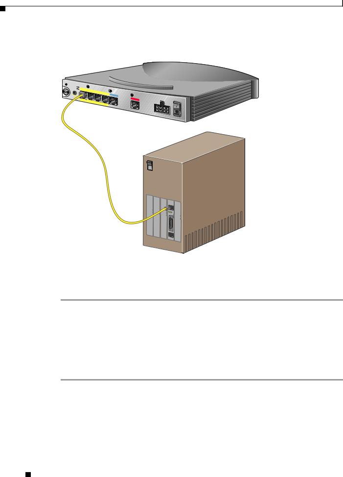
Connecting a Server, PC, or Workstation
TO HUB
TO PC
ETHERNET 10 BASE T
Cisco 804 |
IDSL |
|
+5, -24, -71 VDC
 AUX
AUX
0 |
OK |
LAN |
SER |
|
|
AUX |
|
|
Connect the yellow cable to one of the following ports:
•The yellow Ethernet port on your Cisco 802 IDSL router.
•Any of the yellow Ethernet ports on your Cisco 804 IDSL router.
Step 1 Connect the other end of the cable to the server, PC, or workstation.
Step 2 Check the LED corresponding to the connected port after router power-up:
•The LINK LED is on the Cisco 802 IDSL back panel.
•ETHERNET 1, 2, 3, and 4 LEDs are on the Cisco 804 IDSL front panel.
Step 3 If the LINK or ETHERNET 1 LED is not on, try pressing the TO HUB/TO PC button.
Step 4 If the ETHERNET 2, 3, or 4 LED is not on, see the Cisco 800 Series Routers Hardware Installation Guide.
Installing and Configuring Cisco 802 IDSL and Cisco 804 IDSL Routers
8 |
78-10368-03 |
|
|
Loading...