


 Loading...
Quick Start Guide
Cisco 800 Series Router Cabling and Setup
1Cisco One-Year Limited Hardware Warranty Terms
2Overview
3Parts List
4Verify the PC Setup
5Connect the Cisco 800 Series Router to a PC
6Connect the Cisco 800 Series Router to a Hub
7Connect an ISDN Line
8Connect Telephone, Fax Machine, or Modem
9Connect the Power and Turn On the Router
10Verifying the LEDs
11Obtaining Documentation
12Documentation Feedback
13Cisco Product Security Overview
14Obtaining Technical Assistance
15Obtaining Additional Publications and Information
1 Cisco One-Year Limited Hardware Warranty Terms
There are special terms applicable to your hardware warranty and various services that you can use during the warranty period. Your formal Warranty Statement, including the warranties and license agreements applicable to Cisco software, is available on Cisco.com. Follow these steps to access and download the Cisco Information Packet and your warranty and license agreements from Cisco.com.
1.Launch your browser, and go to this URL: http://www.cisco.com/univercd/cc/td/doc/es_inpck/cetrans.htm The Warranties and License Agreements page appears.
2.To read the Cisco Information Packet, follow these steps:
a.Click the Information Packet Number field, and make sure that the part number 78-5235-03A0 is highlighted.
b.Select the language in which you would like to read the document.
c.Click Go.
The Cisco Limited Warranty and Software License page from the Information Packet appears.
d.Read the document online, or click the PDF icon to download and print the document in Adobe Portable Document Format (PDF).
Note You must have Adobe Acrobat Reader to view and print PDF files. You can download the reader from Adobe’s website: http://www.adobe.com
3.To read translated and localized warranty information about your product, follow these steps:
a.Enter this part number in the Warranty Document Number field: 78-10747-01C0
b.Select the language in which you would like to view the document.
c.Click Go.
The Cisco warranty page appears.
d.Read the document online, or click the PDF icon to download and print the document in Adobe Portable Document Format (PDF).
You can also contact the Cisco service and support website for assistance:
http://www.cisco.com/public/Support_root.shtml.
Duration of Hardware Warranty
One (1) Year
Replacement, Repair, or Refund Policy for Hardware
Cisco or its service center will use commercially reasonable efforts to ship a replacement part within ten (10) working days after receipt of a Return Materials Authorization (RMA) request. Actual delivery times can vary, depending on the customer location.
Cisco reserves the right to refund the purchase price as its exclusive warranty remedy.
To Receive a Return Materials Authorization (RMA) Number
Contact the company from whom you purchased the product. If you purchased the product directly from Cisco, contact your Cisco Sales and Service Representative.
2

Complete the information below, and keep it for reference.
Company product purchased from
Company telephone number
Product model number
Product serial number
Maintenance contract number
2 Overview
This document describes the basic process of cabling and configuring the Internet access device, the Cisco 800 series router. For advanced cabling information, refer to the Cisco 800 Series Router Hardware Installation Guide. For advanced configuration information, refer to the Cisco 800 Series Router Software Configuration Guide. These documents are available on Cisco.com.
3 Parts List
The shipment of your Cisco 800 series router includes the following items:
•One Cisco 800 series router
•One yellow Ethernet cable
•One orange ISDN S/T cable (Cisco 801 and Cisco 803 only)
•One red ISDN U cable (Cisco 802 and Cisco 804 only)
•One RJ-45-to-RJ-11 adapter cable (for use with the red ISDN U cable)
•One blue console cable
•One DB-9-to-RJ-45 adapter (for use with the blue console cable)
•One DB-25-to-RJ-45 adapter (for use with the blue console cable)
•One black power supply
•One black power supply cord
•Product Documentation
4 Verify the PC Setup
Before you begin, verify that each computer that will be connected to the router has a network interface card (NIC) installed and that Transmission Control Protocol/Internet Protocol (TCP/IP) has been loaded and configured. For more information on how to configure TCP/IP, refer to the PC Configuration Instructions to Establish Cisco Router-to-PC Communications, which is available on Cisco.com.
3
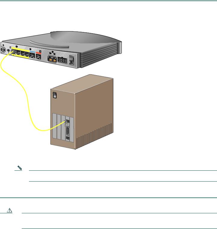
5 Connect the Cisco 800 Series Router to a PC
Follow these steps to connect the Cisco 800 series router to a PC:
Step 1 Connect the yellow Ethernet cable from the yellow Ethernet port (Cisco 801 and 802 routers) or from the yellow Ethernet port with the number 0 (Cisco 803 and 804 routers) on the back panel of the router to the Ethernet port on the NIC on the computer.
Figure 1 Connecting a Cisco 800 Series Router to a PC
HUB
NO HUB
ETHERNET 10 |
BASE T |
|
Cisco 803
 AUX
AUX
0 |
OK |
LAN |
SER |
|
|
AUX |
|
|
Step 2 Verify that the HUB/NO HUB switch on the left side of the back panel has been set to the NO HUB position (out). If the button is in, press it to set it to the out position.
Note The HUB/NO HUB button corresponds to the Ethernet port on Cisco 801 and 802 routers and to Ethernet port 0 on Cisco 803 and 804 routers.
Step 3 For Cisco 803 and 804 routers, connect additional computers to the Cisco 800 series router by connecting Ethernet cables from the Ethernet ports labeled with the numbers 1, 2, and 3 to the Ethernet ports on the computers.
Caution Always connect the yellow cable or Ethernet cable that you supply to the yellow ports on the router. Do not connect the cable to an ISDN S/T or U port or to a Network Termination 1 (NT1) device. Accidently connecting the cable to the wrong port can damage your router.
4

6 Connect the Cisco 800 Series Router to a Hub
Follow these steps to connect the Cisco 800 series router to a hub:
Step 1 Connect the yellow Ethernet cable from the yellow Ethernet port (Cisco 801 and 802 routers) or from the yellow Ethernet port with the number 0 (Cisco 803 and 804 routers) on the back panel of the router to the Ethernet port on the hub.
Figure 2 Connecting a Cisco 800 Series Router to a Hub
HUB
NO HUB
ETHERNET 10 |
BASE T |
|
Cisco 803
2X |
10/100 |
|
|
3X |
|
|
|
4X |
6X 
 7X 8X
7X 8X
MDI |
MDI-X |
1528 Micro Hub 10/100
Step 2 Verify that the HUB/NO HUB switch on the left side of the back panel has been set to the HUB position (in). If the button is out, press it to set it to the in position.
Note The HUB/NO HUB button corresponds to the Ethernet port on Cisco 801 and 802 routers and to Ethernet port 0 on Cisco 803 and 804 routers.
Caution Always connect the yellow cable or Ethernet cable that you supply to the yellow ports on the router. Do not connect the cable to an ISDN S/T or U port or to a Network Termination 1 (NT1) device. Accidently connecting the cable to the wrong port can damage your router.
5
Loading...