


 Loading...
Catalyst 6509-NEB Switch and Cisco OSR-7609
Router Upgrade Note
Note
Note
Product Number: WS-6509-NEB-UPGRD=
This publication describes how to upgrade your Catalyst 6509-NEB switch or Cisco OSR-7609 Router to use the Supervisor Engine 720 and the Supervisor Engine 32.
AC-Input Systems—If your switch or router is using an AC-input power supply, you are required to install the WS-CAC-3000W power supply. The 3000 W AC-input provides a power output to power the fan tray.
DC-Input Systems—If your switch or router is using a DC-input power supply, you are required to install the WS-CDC-2500W or PWR-4000-DC power supply. You must provide a separate, direct connection to power the fan tray. Each input of the fan tray is rated 10 A @ -40 to -60 VDC.
Caution It is important that you follow the steps in this document in the order they are presented.
Corporate Headquarters:
Cisco Systems, Inc., 170 West Tasman Drive, San Jose, CA 95134-1706 USA
Copyright © 2004–2006 Cisco Systems, Inc. All rights reserved.
Contents
Contents
This publication consists of the following sections:
•Safety Overview, page 2
•Parts List, page 3
•Required Tools, page 3
•Installation Guidelines, page 4
•Shutting Down the System, page 4
•Replacing the Panel Safety Cover, page 5
•Replacing the Fan Tray, page 7
•Replacing the Power Supply, page 10
•Connecting Power to the Fan Tray, page 13
•Replacing the Supervisor Engine, page 17
•Powering Up the System, page 21
•Verifying Installation, page 22
•Related Documentation, page 23
•Obtaining Documentation, page 23
•Documentation Feedback, page 24
•Cisco Product Security Overview, page 24
•Obtaining Technical Assistance, page 25
•Obtaining Additional Publications and Information, page 27
Safety Overview
Safety warnings appear throughout this publication in procedures that, if performed incorrectly, may harm you. A warning symbol precedes each warning statement.
Warning IMPORTANT SAFETY INSTRUCTIONS
This warning symbol means danger. You are in a situation that could cause bodily injury. Before you work on any equipment, be aware of the hazards involved with electrical circuitry and be familiar with standard practices for preventing accidents. Use the statement number provided at the end of each warning to locate its translation in the translated safety warnings that accompanied this device. Statement 1071
SAVE THESE INSTRUCTIONS
Warning Before performing any of the following procedures, ensure that power is removed from the DC circuit.
Statement 1003
Catalyst 6509-NEB Switch and Cisco OSR-7609 Router Upgrade Note
2 |
78-16162-02 |
|
|
Parts List
Warning This unit might have more than one power supply connection. All connections must be removed to de-energize the unit. Statement 1028
Warning Only trained and qualified personnel should be allowed to install, replace, or service this equipment.
Statement 1030
Warning Hazardous voltage or energy is present on the backplane when the system is operating. Use caution when servicing. Statement 1034
Warning This product requires short-circuit (overcurrent) protection, to be provided as part of the building installation. Install only in accordance with national and local wiring regulations. Statement 1045
Warning When installing or replacing the unit, the ground connection must always be made first and disconnected last. Statement 1046
Parts List
The following items are included in the upgrade kit:
•One high speed fan tray
The high speed fan tray provides additional cooling for the Supervisor Engine 720 and the Supervisor Engine 32.
The high speed fan tray requires external power, either from the 3000 W AC-input power supply or from an external DC power source. The fan tray ships with power wires secured at each terminal block. Use these wires to connect the fan tray to the 3000 W AC-input power supply using the supplied cable, or remove them to connect to a DC power source.
•One panel safety cover
The panel safety cover provides increased chassis airflow.
•Two fan tray power cables (for AC-input systems)
The fan tray power cable provides a connection between the fan tray and the 3000 W AC-input power supply. Two cables are provided for systems with redundant power supplies.
Required Tools
These tools are required to perform the installation:
•Number 1 Phillips-head screwdriver
•Number 2 Phillips-head screwdriver
•Flat-blade screwdriver (for DC-input systems)
Catalyst 6509-NEB Switch and Cisco OSR-7609 Router Upgrade Note
|
78-16162-02 |
3 |
|
|
|
Installation Guidelines
Installation Guidelines
Follow these guidelines when upgrading the chassis:
•If your switch or router is using an AC-input power supply, you are required to install the WS-CAC-3000W power supply. The 3000 W AC-input provides a power output to power the fan tray.
•If your switch or router is using a DC-input power supply, you are required to install the WS-CDC-2500W or PWR-4000-DC power supply. You must provide a separate, direct connection to power the fan tray. Each input of the fan tray is rated 10 A @ -40 to -60 VDC.
•Observe the following cautions:
Caution It is important that you follow the steps in this document in the order they are presented.
Caution Always use an ESD wrist strap when handling modules or coming into contact with internal components.
Caution Use both hands to install and remove power supplies. Each Catalyst 6500 series AC-input power supply weighs between 22 pounds (9.9 kg) and 28 pounds (12.6 kg).
Caution Do not exert too much pressure on the ejector levers. They will bend and be damaged.
Caution In a system with dual power supplies, connect each power supply to a separate input source. In case of a power source failure, the second source will most likely still be available.
Shutting Down the System
To perform the upgrade, you must shut down the system.
Before you shut down the system, you should first upload the current configuration to a server. This saves time when bringing the module back online. You can recover the configuration by downloading it from the server to the nonvolatile memory of the supervisor engine. For more information, refer to the “Working with Configuration Files” chapter in the Catalyst 6500 Series Software Configuration Guide.
To properly shut down the system, follow these steps:
Step 1 Upload the current configuration to a server. On any modules running Cisco IOS, save the running configuration.
Warning Before working on a system that has an on/off switch, turn OFF the power and unplug the power cord.
Statement 1
Catalyst 6509-NEB Switch and Cisco OSR-7609 Router Upgrade Note
4 |
78-16162-02 |
|
|
Replacing the Panel Safety Cover
Warning This unit might have more than one power supply connection. All connections must be removed to de-energize the unit. Statement 1028
Step 2 Depending on how your system is powered, perform one of the two sets of substeps below.
AC-Input Systems
a.Turn the power switch to the Off (0) position on each power supply. Turning the power switch off also disengages a pawl that unlocks the power supply from the chassis.
b.Disconnect the power cord from the power source.
c.Loosen the screw on the cable retention device, and disconnect the power cord from the power supply being removed.
Note The AC power cord for the 4000 W power supply is hard wired and cannot be removed from the supply.
Warning Before performing any of the following procedures, ensure that power is removed from the DC circuit.
Statement 1003
DC-Input Systems
a.Verify that power is off to the DC circuit for each power supply. As an added safety precaution, you should secure the source DC circuit breaker switch in the OFF position with electrical tape.
b.Turn the power switch to the Off (0) position on each power supply. Turning the power switch off also disengages a pawl that unlocks the power supply from the chassis.
Replacing the Panel Safety Cover
This section describes how to remove and install the panel safety cover for the Catalyst 6509-NEB switch and Cisco OSR-7609 Router. A number 1 Phillips-head screwdriver is required to perform this procedure.
Caution Always use an ESD wrist strap when handling modules or coming into contact with internal components.
Warning Hazardous voltage or energy is present on the backplane when the system is operating. Use caution when servicing. Statement 1034
To remove the panel safety cover, perform these steps:
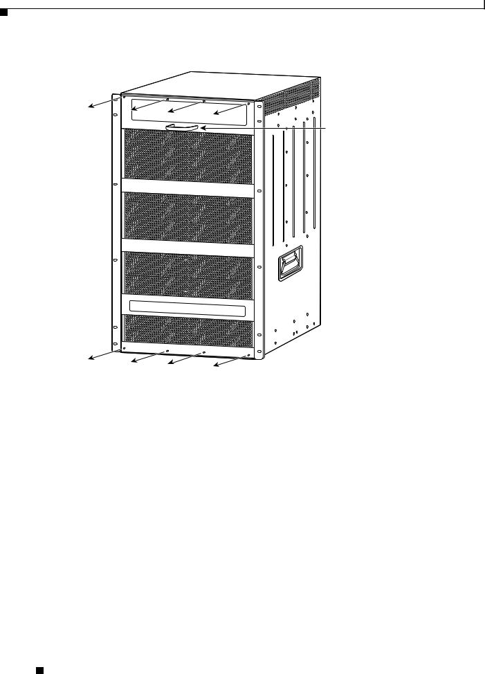
Step 1 Use a number 1 Phillips-head screwdriver to remove the 8 panel screws, 4 each located along the top and bottom of the chassis. (See Figure 1.) Set the screws aside.
Step 2 Grasp the panel handle and pull the panel away from the chassis.
Catalyst 6509-NEB Switch and Cisco OSR-7609 Router Upgrade Note
|
78-16162-02 |
5 |
|
|
|
Replacing the Panel Safety Cover
Figure 1 Removing the Panel Safety Cover
Panel handle
105072
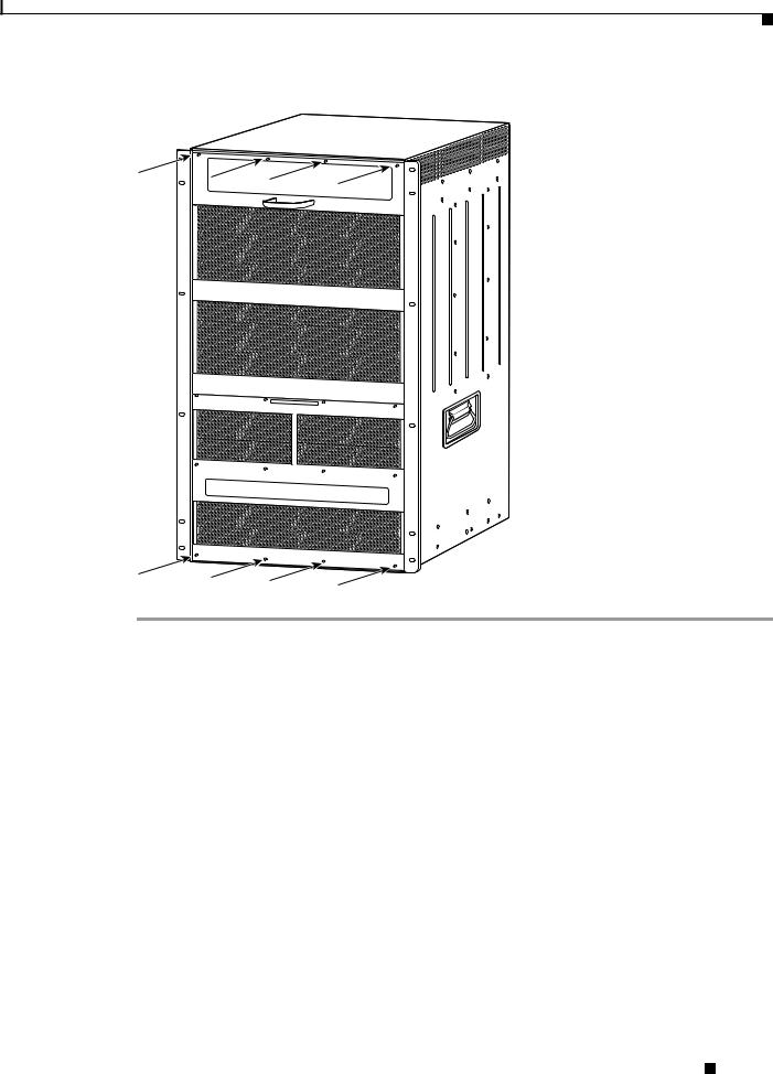
Step 3 On the new panel safety cover, grasp the panel handle and press the panel into place, starting at the bottom of the chassis and working up. Be careful not to damage the EMI gasket.
Step 4 Use a number 1 Phillips-head screwdriver to install the 8 panel screws, 4 each located along the top and bottom of the chassis. (See Figure 2.)
Step 5 Proceed to the “Replacing the Fan Tray” section on page 7 to replace the fan tray.
Catalyst 6509-NEB Switch and Cisco OSR-7609 Router Upgrade Note
6 |
78-16162-02 |
|
|
Replacing the Fan Tray
Figure 2 Installing the Panel Safety Cover
105071
Replacing the Fan Tray
This section describes how to remove and install the fan tray for the Catalyst 6509-NEB switch and Cisco OSR-7609 Router. A flat-blade or number 2 Phillips-head screwdriver is required to perform this procedure.
Catalyst 6509-NEB Switch and Cisco OSR-7609 Router Upgrade Note
|
78-16162-02 |
7 |
|
|
|

Replacing the Fan Tray
Removing the Fan Tray
Warning When removing the fan tray, keep your hands and fingers away from the spinning fan blades. Let the fan blades completely stop before you remove the fan tray. Statement 258
To remove the existing fan tray, follow these steps:
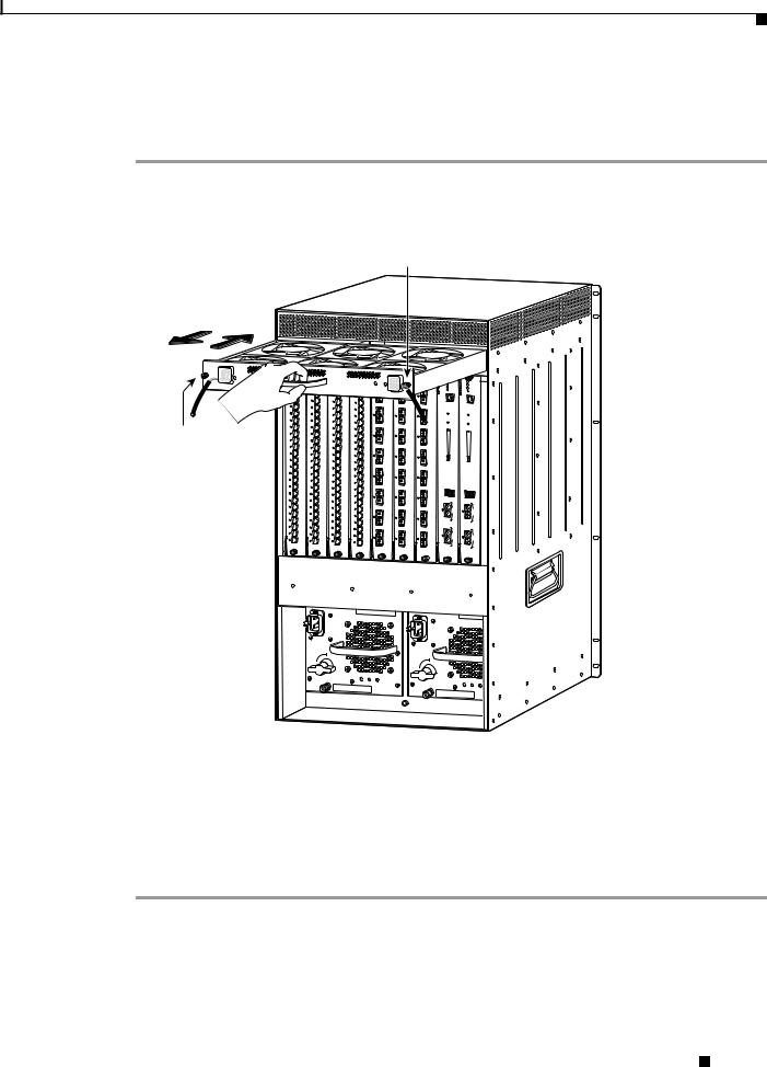
Step 1 Use a flat-blade or number 2 Phillips-head screwdriver to loosen the two captive installation screws on the fan tray by turning them counterclockwise. (See Figure 3.)
Figure 3 Removing the Fan Tray
Captive installation screw
FAN
STATUS
Captive installation screw
|
STATUS |
LINK |
LINK |
LINK |
LINK |
LINK |
LINK |
LINK |
LINK |
LINK |
LINK |
LINK |
LINK |
LINK |
LINK |
LINK |
LINK |
LINK |
LINK |
LINK |
LINK |
LINK |
LINK |
LINK |
LINK |
LINK |
LINK |
LINK |
LINK |
LINK |
LINK |
LINK |
LINK |
LINK |
LINK |
LINK |
LINK |
LINK |
LINK |
LINK |
LINK |
LINK |
LINK |
LINK |
LINK |
LINK |
LINK |
LINK |
LINK |
STATUS
LINK
LINK
LINK
LINK
LINK
LINK
LINK
LINK
LINK
LINK
LINK
LINK
LINK
LINK
LINK
LINK
LINK
LINK
LINK
LINK
LINK
LINK
LINK
LINK
STATUS
LINK
LINK
LINK
LINK
LINK
LINK
LINK
LINK
LINK
LINK
LINK
LINK
LINK
LINK
LINK
LINK
LINK
LINK
LINK
LINK
LINK
LINK
LINK
LINK
STATUS |
STATUS |
STATUS |
LINK |
LINK |
LINK |
LINK |
LINK |
LINK |
|
||
LINK |
LINK |
LINK |
LINK |
LINK |
LINK |
LINK |
LINK |
LINK |
|
||
LINK |
LINK |
LINK |
LINK |
LINK |
LINK |
LINK |
LINK |
LINK |
|
SUPERVISOR2
STATUS SYSTEM CONSOLE PWR MGMT RESET
2GE-SUP2-X6K-WS |
SUPERVISOR2 |
STATUS SYSTEM CONSOLE PWR MGMT RESET
2GE-SUP2-X6K-WS
o
o
INPUT |
FAN |
OUTPUT |
OK |
OK |
FAIL |
INPUT |
FAN |
OUTPUT |
OK |
OK |
FAIL |
30696
Step 2 Grasp the fan tray handle with one hand and pull the fan tray outward about 1 inch; rock it gently, if necessary, to unseat the power connector from the backplane. Wait for the fans to stop spinning.
Step 3 Once the fans have stopped spinning, pull the fan tray out further and support the underside of the fan tray with the other hand.
Step 4 Pull the fan tray clear of the chassis, and put it in a safe place.
Catalyst 6509-NEB Switch and Cisco OSR-7609 Router Upgrade Note
8 |
78-16162-02 |
|
|
Replacing the Fan Tray
Installing the High Speed Fan Tray
To install the high speed fan tray, follow these steps:
Step 1 Hold the fan tray with the fans facing down and the FAN FAIL LED on the right. (See Figure 4.)
Figure 4 Installing the High Speed Fan Tray
Captive installation screw
48V INPUT 1
INPOUT POWER
GOOD
RTN -48VDC GND
WS-C6500-NEB-FAN2
Captive installation screw
|
HIGH SPEED FAN |
|
STATUS |
LINK |
LINK |
LINK |
LINK |
LINK |
LINK |
LINK |
LINK |
LINK |
LINK |
LINK |
LINK |
LINK |
LINK |
LINK |
LINK |
LINK |
LINK |
LINK |
LINK |
LINK |
LINK |
LINK |
LINK |
LINK |
LINK |
LINK |
LINK |
LINK |
LINK |
LINK |
LINK |
LINK |
LINK |
LINK |
LINK |
LINK |
LINK |
LINK |
LINK |
LINK |
LINK |
LINK |
LINK |
LINK |
LINK |
LINK |
LINK |
STATUS
LINK
LINK
LINK
LINK
LINK
LINK
LINK
LINK
LINK
LINK
LINK
LINK
LINK
LINK
LINK
LINK
LINK
LINK
LINK
LINK
LINK
LINK
LINK
LINK
STATUS
LINK
LINK
LINK
LINK
LINK
LINK
LINK
LINK
LINK
LINK
LINK
LINK
LINK
LINK
LINK
LINK
LINK
LINK
LINK
LINK
LINK
LINK
LINK
LINK
|
48V INPUT 2 |
SUPERVISOR2 |
|
2GE-SUP2-X6K-WS |
SUPERVISOR2 |
SYSTEM |
2GE-SUP2-X6K-WS |
||
|
|
|
|
|
STATUS |
|
|
STATUS |
|
|
|
|
|
|
SYSTEM |
|
|
|
|
FAN FAIL |
STATUS |
|
STATUS |
STATUS |
CONSOLE |
|
|
CONSOLE |
|
INPOUT POWER |
|
PWR |
|
|
|
||||
|
GOOD |
|
|
|
MGMT |
|
|
PWR |
|
|
|
|
|
|
RESET |
|
|
MGMT |
|
|
RTN |
-48VDC |
GND |
|
|
|
|
RESET |
|
LINK |
|
|
|
|
|
|
|||
|
|
LINK |
|
LINK |
|
|
|
|
|
LINK |
LINK |
LINK |
LINK |
LINK |
LINK |
LINK |
LINK |
LINK |
|
||
LINK |
LINK |
LINK |
LINK |
LINK |
LINK |
LINK |
LINK |
LINK |
|
||
LINK |
LINK |
LINK |
o
o
INPUT |
FAN |
OUTPUT |
OK |
OK |
FAIL |
INPUT |
FAN |
OUTPUT |
OK |
OK |
FAIL |
105068
Step 2 Place the fan tray into the front chassis cavity so that it rests on the chassis, and then lift the fan tray up slightly, aligning the top and bottom chassis guides.
Step 3 Push the fan tray into the chassis until the power connector seats in the backplane and the captive installation screws make contact with the chassis.
Step 4 Use a flat-blade or number 2 Phillips-head screwdriver to tighten the captive installation screws.
Step 5 Proceed to the “Replacing the Power Supply” section on page 10 to replace the power supply.
Catalyst 6509-NEB Switch and Cisco OSR-7609 Router Upgrade Note
|
78-16162-02 |
9 |
|
|
|
Loading...