


 Loading...
Getting Started
Catalyst 3750G Integrated Wireless LAN Controller Switch
Getting Started Guide
INCLUDING LICENSE AND WARRANTY
1About this Guide
2Taking Out What You Need
3Running Express Setup
4Managing the Switch
5Preparing the Wireless LAN Controller for Operation
6Planning Switch Stacks
7Rack-Mounting
8In Case of Difficulty
9Obtaining Documentation
10Documentation Feedback

11Cisco Product Security Overview
12Obtaining Technical Assistance
13Obtaining Additional Publications and Information
14Cisco Limited Lifetime Hardware Warranty Terms
1 About this Guide
This guide provides instructions on how to use Express Setup to initially configure your Catalyst 3750G Integrated Wireless LAN Controller switch. It also covers switch management
options, the configuration procedures for the controller, basic rack-mounting procedures, stacking, port and module connections, power connection procedures, and any troubleshooting help.
The Catalyst 3750G Integrated Wireless LAN Controller switch has an integrated Cisco wireless LAN controller that can support Cisco Lightweight Access Points. The switch also has two internal Gigabit Ethernet ports (ports 27 and 28) that connect the switch and the controller. The integrated wireless LAN controller centralizes and simplifies network management of a wireless LAN. It collapses large numbers of managed lightweight access points and client devices into a single unified system.
For additional installation and configuration information for wireless LAN controller switches, see the Catalyst 3750 documentation on Cisco.com. For more information on the controller, see the Cisco Wireless LAN Controller Configuration Guide, Release 4.0 or later on Cisco.com. For system requirements, important notes, limitations, open and resolved caveats, and last-minute documentation updates, see the release notes, also on Cisco.com.
When using the online publications, refer to the documents that match the Cisco IOS software version running on the switch. The software version is on the Cisco IOS label on the switch rear panel.
For translations of the warnings that appear in this publication, see the Regulatory Compliance and Safety Information for the Catalyst 3750 Switch that accompanies this guide.
2 Taking Out What You Need
Follow these steps:
1.Unpack and remove the switch and the accessory kit from the shipping box.
2.Return the packing material to the shipping container, and save it for future use.
3.Verify that you have received the items shown on page 3. If any item is missing or damaged, contact your Cisco representative or reseller for instructions.
Note If you do not specify the length of the StackWise cable, the 0.5-meter cable is supplied.
2

Shipping Box Contents
Catalyst 3750G
Integrated Wireless LAN
Controller switch
1 |
2 |
3 |
4 |
5 |
6 |
7 |
8 |
10 |
|
|
|
|
|
9 |
11 |
12 |
|
|
|
|
|
|
|
|
|
Catalyst 3750G |
PoE-24 |
|
|
|
|
|
|
|
|
|
|
Wireless |
|
|
|
|
|
|
|
|
|
|
|
|
LAN Controller |
|
13 |
14 |
15 |
16 |
|
|
|
|
|
|
|
|
|
|
|
17 |
18 |
19 |
20 |
|
|
|
|
|
|
|
|
|
|
|
21 |
22 |
23 |
24 |
|
|
|
|
|
|
|
|
|
|
|
25 |
|
|
|
|
|
|
|
|
|
|
|
|
|
26 |
|
Two 19-inch |
|
mounting brackets |
|
Four number-12 Phillips machine screws |
0.5-meter, 1-meter or 3-meter |
Four number-8 Phillips truss-head screws |
StackWise cable |
Six number-8 Phillips flat-head screws |
|
Connector cover for redundant
power system (RPS)
Console cable
Two number-4 pan-head screws
ProductCisco
Registration
Ownershipcard
AC power cord
|
|
|
Regulatory |
|
|||
Catalyst |
|
and |
Safety |
|
|
||
3750G |
Catalyst |
|
|
||||
Integrated |
|
for the |
Compliance |
||||
Controller |
Wireless |
|
3750 |
|
|
||
|
|
|
|
Information |
|||
|
Switch |
|
|
Switch |
|||
Guide |
|
|
|
|
|
||
Documentation
Cable guide
One black Phillips machine screw
Four rubber mounting feet
3
Equipment that You Supply to Run Express Setup
You need to supply this equipment to run Express Setup:
•PC
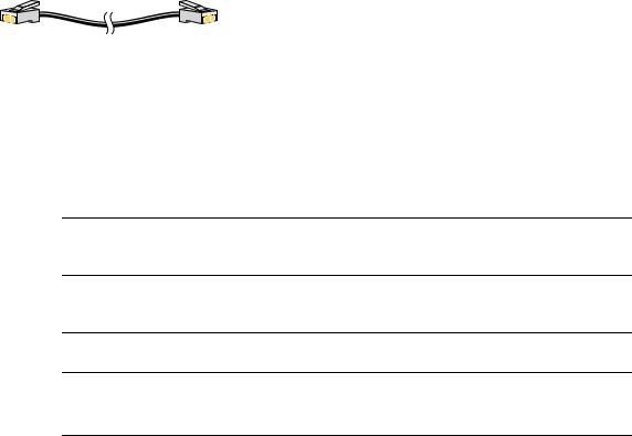
•Ethernet (Category 5) straight-through cable (as shown)
3 Running Express Setup
When you first set up the switch, you should use Express Setup to enter the initial IP information. Doing this enables the switch to connect to local routers and the Internet. You can then access the switch through the IP address for further configuration.
To run Express Setup:
Step 1 Verify that no devices are connected to the switch. During Express Setup, the switch acts as a DHCP server. If your PC has a static IP address, before you begin, change your PC settings to temporarily use DHCP.
Step 2 Connect the AC power cord to the switch and to a grounded AC outlet. The power-on self-test (POST) begins. During POST, the LEDs blink while a series of tests verify that the switch functions properly.
Step 3 Wait for the switch to complete POST. It might take several minutes for the switch to complete POST.
Step 4 Verify that POST has completed by confirming that the SYST LED remains green. If the switch fails POST, the SYST LED turns amber.
POST errors are usually fatal. Call Cisco Systems immediately if your switch fails POST.
4
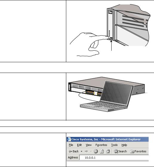
Step 5 Press and hold the Mode button for 3 seconds. When all of the LEDs above the Mode button turn green, release the Mode button.
If the LEDs above the Mode button begin to blink after you press the button, release it. Blinking LEDs mean that the switch has already been configured and cannot go into Express Setup mode. For more information, see the “Resetting the Switch” section on page 35.
 SYST
SYST
RPS
MASTR
STAT
DUPLX
SPEED
STACK
PoE
button
Step 6 Verify that the switch is in Express Setup mode by confirming that all LEDs above the Mode button are green. (On some switch models, the RPS LED remains off.)
Step 7 Connect a straight-through Category 5 Ethernet cable (not provided) to any 10/100/1000 Ethernet port on the switch front panel and to the Ethernet port on the PC.
CataWlyst 3750G
ireless LAN CoPntorEol-l2e4r
DHCP-enabled PC
Step 8 Verify that the LEDs on both Ethernet ports are green.
Step 9 Wait 30 seconds.
Step 10 Launch a web browser on your PC. Enter the IP address 10.0.0.1 in the web browser, and press Enter.
5
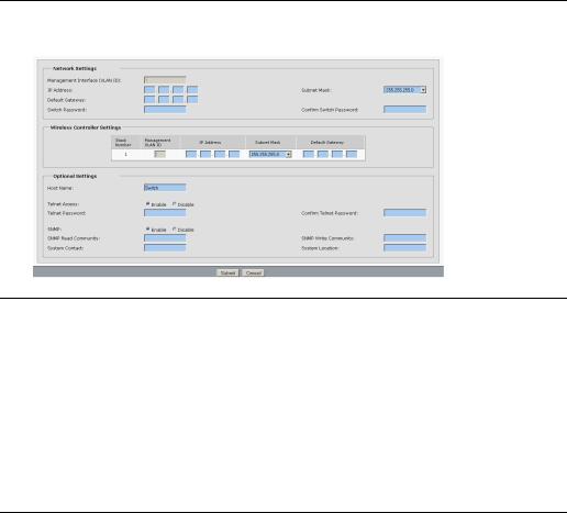
Step 11 The Express Setup page appears. If it does not appear, see the “In Case of Difficulty” section on page 34 for help.
Step 12 Enter this information in the Network Settings fields:
•In the Management Interface (VLAN ID) field, the default is 1. Enter a new VLAN ID only if you want to change the management interface through which you manage the switch and to which you assign IP information. The VLAN ID range is 1 to 1001.
•In the IP Address field, enter the IP address of the switch. In the IP Subnet Mask field, click the drop-down arrow, and select an IP Subnet Mask.
•In the Default Gateway field, enter the IP address for the default gateway (router).
•Enter your password in the Switch Password field. The password can be from 1 to 25 alphanumeric characters, can start with a number, is case sensitive, allows embedded spaces, but does not allow spaces at the beginning or end. In the Confirm Switch Password field, enter your password again.
6

Step 13 In the Wireless Controller Settings area (see the Figure in Step 11), the stack number displays the stack-member number of the switch.
Enter this information:
•In the Management Interface (VLAN ID) field, the default is 0. Enter a new VLAN ID only if you want to change the management interface through which you manage the controller and to which you assign IP information. If you entered a VLAN ID other than 1 in Step 12, then enter the same VLAN ID for the controller. The VLAN ID range is 0 to 1001.
•In the IP Address field, enter the IP address of the controller.
•In the IP Subnet Mask field, click the drop-down arrow, and select an IP Subnet Mask.
•In the Default Gateway field, enter the IP address for the default gateway (router).
Note If you are connecting more than one wireless controller switch, multiple rows appear in the wireless controller settings area.
7

Step 14 (Optional) You can enter the Optional Settings information now or enter it later by using the device manager interface:
•In the Host Name field, enter a name for the switch. The host name is limited to 31 characters; embedded spaces are not allowed.
•In the Telnet Access field, click Enable if you are going to use Telnet to manage the switch by using the command-line interface (CLI). If you enable Telnet access, you must enter a Telnet password.
•In the Telnet Password field, enter a password. The Telnet password can be from
1 to 25 alphanumeric characters, is case sensitive, allows embedded spaces, but does not allow spaces at the beginning or end. In the Confirm Telnet Password field, re-enter the Telnet password.
•In the SNMP field, click Enable to enable Simple Network Management Protocol (SNMP). Enable SNMP only if you plan to manage switches by using CiscoWorks 2000 or another SNMP-based network-management system.
If you enable SNMP, you must enter a community string in the SNMP Read Community field, the SNMP Write Community field, or both. SNMP community strings authenticate access to MIB objects. Embedded spaces are not allowed in SNMP community strings. When you set the SNMP read community, you can access SNMP information, but you cannot modify it. When you set the SNMP write community, you can both access and modify SNMP information.
•In the System Contact field, enter the name of the person who is responsible for the switch. In the System Location field, enter the wiring closet, floor, or building where the switch is located.
Step 15 Click Submit to save your settings, or click Cancel to clear your settings.
When you click Submit, the switch is configured and exits Express Setup mode. The PC displays a warning message and then tries to connect with the new switch IP address. If you configured the switch with an IP address that is in a different subnet from the PC, connectivity between the PC and the switch is lost.
Step 16 Disconnect the switch from the PC, and install the switch in your network. See the “Managing the Switch” section on page 9 for information about configuring and managing the switch.
If you need to rerun Express Setup, see the “Resetting the Switch” section on page 35.
8
Refreshing the PC IP Address
After you complete Express Setup, you should refresh the PC IP address:
•For a dynamically assigned IP address, disconnect the PC from the switch, and reconnect it to the network. The network DHCP server assigns a new IP address to the PC.
•For a statically assigned IP address, change it to the previously configured IP address.
4 Managing the Switch
After you complete Express Setup and install the switch in your network, use the device manager or other management options described in this section for further configuration.
Using the Device Manager
The simplest way to manage the switch is by using the device manager that is in the switch memory. This is an easy-to-use web interface that offers quick configuration and monitoring. You can access the device manager from anywhere in your network through a web browser.
Follow these steps:
1.Launch a web browser on your PC or workstation.
2.Enter the switch IP address in the web browser, and press Enter. The device manager page appears.
3.Use the device manager to perform basic switch configuration and monitoring. Refer to the device manager online help for more information.
4.For more advanced configuration, download and run the Cisco Network Assistant, which is described in the next section.
Downloading Cisco Network Assistant
Cisco Network Assistant is a software program that you download from Cisco.com and run on your PC. It offers advanced options for configuring and monitoring multiple devices, including switches, switch clusters, switch stacks, routers, and access points. Network Assistant is free—there is no charge to download, install, or use it.
Follow these steps:
1.Go to this Web address: http://www.cisco.com/go/NetworkAssistant.
You must be a registered Cisco.com user, but you need no other access privileges.
2.Find the Network Assistant installer.
9
3.Download the Network Assistant installer, and run it. (You can run it directly from the Web if your browser offers this choice.)
4.When you run the installer, follow the displayed instructions. In the final panel, click Finish to complete the Network Assistant installation.
Refer to the Network Assistant online help and the getting started guide for more information.
Command-Line Interface
You can enter Cisco IOS commands and parameters through the CLI. Access the CLI either by connecting your PC directly to the switch console port or through a Telnet session from a remote PC or workstation.
Follow these steps:
1.Connect the supplied RJ-45-to DB-9 adapter cable to the standard 9-pin serial port on the PC. Connect the other end of the cable to the switch console port.
2.Start a terminal-emulation program on the PC.
3.Configure the PC terminal emulation software for:
–9600 baud
–8 data bits
–No parity
–1 stop bit
–No flow control
4.Use the CLI to enter commands to configure the switch. See the software configuration guide and the command reference for more information.
Other Management Options
You can use SNMP management applications such as CiscoWorks Small Network Management Solution (SNMS) and HP OpenView to configure and manage the switch. You also can manage it from an SNMP-compatible workstation that is running platforms such as HP OpenView or SunNet Manager.
The Cisco IE2100 Series Configuration Registrar is a network management device that works with embedded Cisco Networking Services (CNS) agents in the switch software. You can use IE2100 to automate initial configurations and configuration updates on the switch.
See the “Accessing Help Online” section on page 36 for a list of supporting documentation.
10
5 Preparing the Wireless LAN Controller for Operation
Follow these major steps to prepare the integrated wireless LAN controller for operation.
•Using the Configuration Wizard to Configure the Controller
•Logging into the Controller
•Verifying Interface Settings and Port Operation
•Connecting Access Points
Using the Configuration Wizard to Configure the Controller
Follow these steps to use the Configuration Wizard to configure the controller for basic operation:
Step 1 Get the initial configuration parameter settings for the controller from your wireless LAN planner.
Step 2 Launch a web browser on your PC.
Step 3 If you have not already done so, assign a static IP address to your PC from the same subnet as the switch; otherwise, the web browser cannot establish a connection with the switch.
11

Step 4 Enter the management IP address of the switch (which you set in Step 12 of the Express Setup) in the web browser, and press Enter. The Catalyst 3750 Device Manager page appears.
Step 5 Under Contents, click Controller Device Manager.
Step 6 When prompted for a username and password, enter admin in each field. The first page of the Configuration Wizard appears.
12
Step 7 In the System Name field, enter the system name, which is the name that you want to assign to the controller. You can enter up to 32 ASCII characters.
Step 8 In the User Name and Password fields, enter the administrative username and password for this controller. You can enter up to 24 ASCII characters for each. The default administrative username and password are both admin.
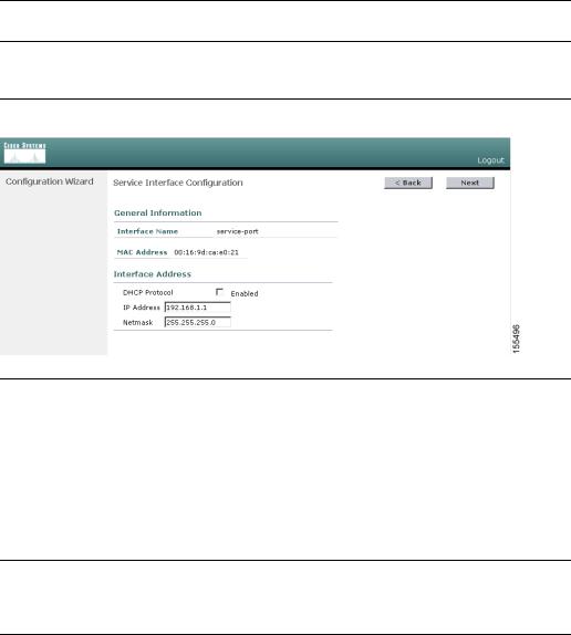
Step 9 Click Next. The Service Interface Configuration page appears.
Step 10 If you want the controller service-port interface to get an IP address from a DHCP server, check the DHCP Protocol Enabled check box. If you do not want to use the service port or if you want to assign a static IP address to the service-port interface, leave the check box unchecked.
The service-port interface controls communications through the service port, which is reserved for out-of-band management of the controller and for system recovery and maintenance in the event of a network failure. Its IP address must be on a different subnet from the management and AP-manager interfaces. You can use this configuration to manage the controller directly or through a dedicated management network to ensure service access during network downtime.
Step 11 If you did not check the DHCP Protocol Enabled check box in Step 10, leave the IP address and the netmask for the service-port interface as they are, or change them as necessary. If you do not want to use the service port, enter 0.0.0.0 for both the IP address and the netmask.
13

Step 12 Click Next. The Management Interface Configuration page appears.
Step 13 Enter the VLAN identifier zero (0) if the VLAN ID set on the switch management interface is 1. If you entered a VLAN ID other than 1 on the switch management interface (see Step 12 of the Running Express Setup section), enter the same VLAN ID for the controller.
Enter the IP address, the netmask, and the gateway for the management interface.
The management interface is the default interface for in-band management of the controller and for connectivity to enterprise services such as authentication, authorization, and accounting (AAA) servers.
Step 14 Enter the IP addresses of the primary and the optional secondary DHCP servers that supply IP addresses to clients, the controller management interface, and, optionally, the service-port interface.
14
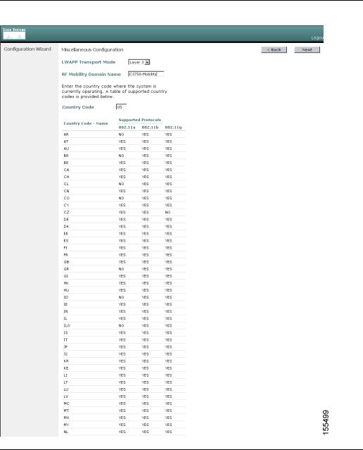
Step 15 Click Next. The Miscellaneous Configuration page appears.
15
Loading...