


 Loading...
Cisco Catalyst Blade Switch
3130 for Dell and Cisco Catalyst Blade Switch 3032 for Dell
Getting Started Guide
This guide provides instructions on how to install the Cisco Catalyst Blade Switch 3130 for Dell and the Cisco Catalyst Blade Switch 3032 for Dell—both hereafter referred to as the switch—in the Dell Modular Server Chassis and how to set up and configure your switch. The Dell Modular Server Chassis—hereafter referred to as the server chassis—is a system that supports up to sixteen server modules and up to six Ethernet switches. You install the switch in one of the chassis I/O module bays on the rear panel of the server chassis.
Also covered in this guide are switch management options and troubleshooting help for the switch.
For details on the number, types, and the location of the module bays and for additional information on the entire modular server system, see the documentation for the Dell PowerEdge Systems at www.support.dell.com.
For additional installation and configuration information about the switch, see the Cisco Catalyst Blade Switch 3000 Series for Dell documentation on Cisco.com. For system requirements, important notes, limitations, open and resolved caveats, and last-minute documentation updates about the switch, see the release notes, also on Cisco.com.
When you use the online publications, refer to the documents that match the Cisco IOS software version that is running on the switch.
Cisco Catalyst Blade Switch 3130 for Dell and Cisco Catalyst Blade Switch 3032 for Dell Getting Started Guide
|
OL-14317-01 |
1 |
|

Cisco Catalyst Blade Switch 3130 for Dell and Cisco Catalyst Blade Switch 3032 for Dell Getting Started Guide
Contents
For translations of the warnings that appear in this publication, see the Regulatory Compliance and Safety Information for the Cisco Catalyst Blade Switch 3000 Series for Dell that accompanies this guide.
Note Before proceeding, read the release notes for the server chassis. The release notes are available on the Dell support website at www.support.dell.com.
Contents
•Taking Out What You Need, page 3
•Switch Description, page 3
•Dell Modular Server Chassis Architecture, page 6
•Installation Warning Statements, page 7
•Installing the Switch in the Server Chassis, page 8
•Configuring the Switch, page 12
•Managing the Switch, page 20
•Planning and Creating a Switch Stack (Only 3130G-S and 3130X-S Switches), page 22
•Connecting to the Switch Ports, page 26
•In Case of Difficulty, page 28
•Obtaining Documentation, Obtaining Support, and Security Guidelines, page 30
•Hardware Warranty Terms, page 31
Cisco Catalyst Blade Switch 3130 for Dell and Cisco Catalyst Blade Switch 3032 for Dell Getting Started Guide
2 |
OL-14317-01 |
|
|
Cisco Catalyst Blade Switch 3130 for Dell and Cisco Catalyst Blade Switch 3032 for Dell Getting Started Guide
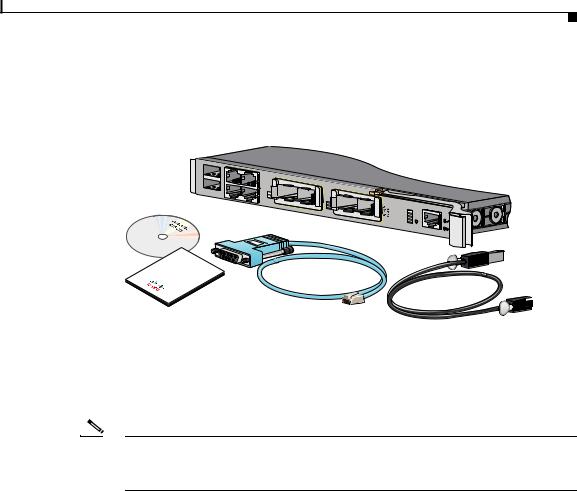
Taking Out What You Need
Taking Out What You Need
These items ship with your switch:
DocumentCD
A |
17X |
19X |
|
|
|
|
|
STK |
|
|
|
|
|
|
|
B |
|
|
1 |
|
|
|
|
|
18X |
21 |
X2- |
|
|
|
|
|
20X 22 |
23 |
X2-2 |
S |
|
|
|
|
|
|
24 |
|
WS-CBS3130X- |
M M S S M S T Y B T C S R R K T |
MODE CONSOLE |
DocumentationProduct

 250289
Follow these steps:
1.Unpack and remove the switch and the accessory kit from the shipping box.
2.Return the packing material to the shipping container, and save it for future use.
Note If you order the switches with the server chassis, the switches are already installed, and no unpacking is required. The unpacking procedure applies only if you order a switch.
Switch Description
These are the available switch models:
|
|
Model |
Description |
|
||
|
|
|
|
|
||
|
|
CBS3032G |
1-Gigabit Ethernet nonstacking-capable switch |
|||
|
|
|
|
|
||
|
|
CBS3130G-S |
1-Gigabit Ethernet stacking-capable switch |
|||
|
|
|
|
|
||
|
|
CBS3130X-S |
10-Gigabit Ethernet stacking-capable switch |
|||
|
|
|
|
|
|
|
|
Cisco Catalyst Blade Switch 3130 for Dell and Cisco Catalyst Blade Switch 3032 for Dell Getting Started Guide |
|
|
|
||
|
||||||
|
OL-14317-01 |
|
|
3 |
||
|
|
|
||||
Cisco Catalyst Blade Switch 3130 for Dell and Cisco Catalyst Blade Switch 3032 for Dell Getting Started Guide
Switch Description
The switch runs the universal software image that has the Cisco IOS code for multiple feature sets. To enable a specific feature set, you must use the software activation feature to install the software license for that feature set. For more information, see the Cisco Software Activation Document for Dell, the release notes, and the software configuration guide on Cisco.com.
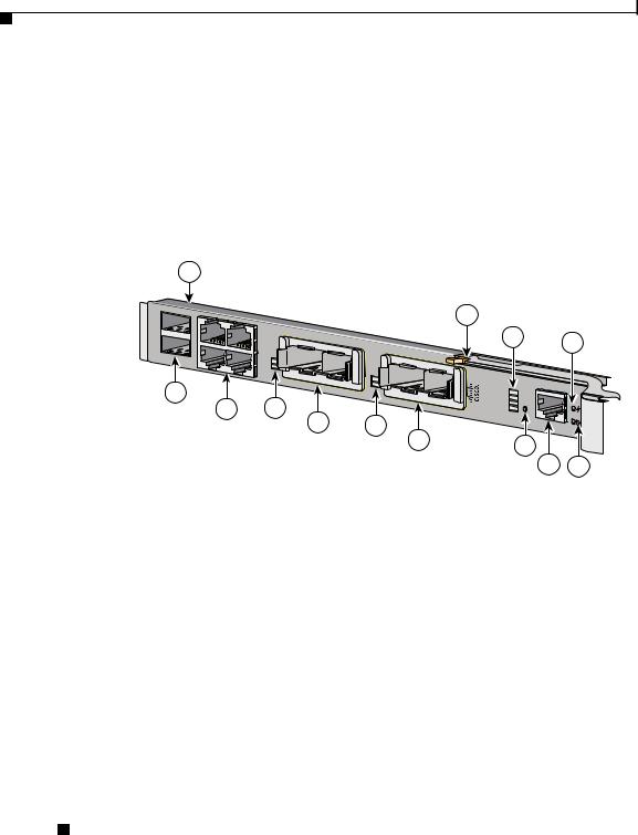
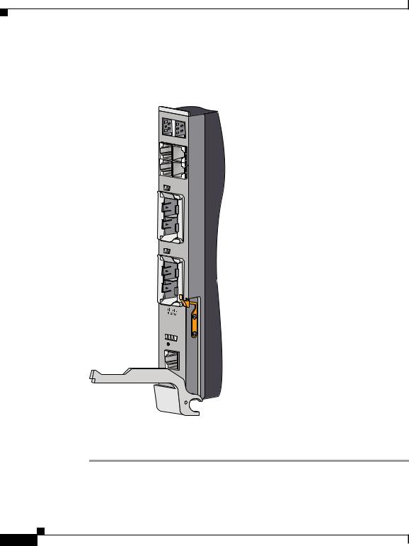
Figure 1 shows the Cisco Catalyst Blade Switch 3130 for Dell as an example. The other switch models have similar components.
Figure 1 |
Switch Front Panel |
1
1 |
17X |
19X |
|
|
STK |
|
|
|
|
2 |
|
|
|
1 |
|
18X |
|
21 |
X2- |
|
20X |
22 |
|
2
3 4
|
8 |
23 |
X2-2 |
24 |
CBS3130X-S |
5 |
WS- |
6 |
7
|
9 |
10 |
|
|
|
M M S S M S T Y B T C S R R K T |
|
MODE CONSOLE |
11

 250198
|
|
|
12 |
13 |
|
|
|
|
|
1 |
Switch |
8 |
Release latch |
|
|
|
|
|
|
2 |
StackWise Plus ports A and B (supported |
9 |
Cisco status LEDs |
|
|
only on the 3130G-S and 3130X-S |
|
|
|
|
switches) |
|
|
|
|
|
|
|
|
3 |
Gigabit Ethernet uplink ports 17 to 20 |
10 |
System Status/ID LED |
|
|
|
|
|
|
4 |
LEDs for ports 21 and 22 |
11 |
Mode button |
|
|
|
|
|
|
5 |
10-Gigabit Ethernet slot 1 |
12 |
Console port |
|
|
or Gigabit Ethernet ports 21 and 22 |
|
|
|
|
|
|
|
|
6 |
LEDs for ports 23 and 24 |
13 |
Power LED |
|
|
|
|
|
|
7 |
10-Gigabit Ethernet slot 2 |
|
|
|
|
or Gigabit Ethernet ports 23 and 24 |
|
|
|
|
|
|
|
|
For more information about the LEDs and their meanings, see the switch hardware installation guide on Cisco.com.
Cisco Catalyst Blade Switch 3130 for Dell and Cisco Catalyst Blade Switch 3032 for Dell Getting Started Guide
4 |
OL-14317-01 |
|
|

Cisco Catalyst Blade Switch 3130 for Dell and Cisco Catalyst Blade Switch 3032 for Dell Getting Started Guide
Switch Description
|
|
Table 1 describes the switch ports. |
Table 1 |
Cisco Catalyst Blade Switch 3130 for Dell and 3032 for Dell Port Descriptions |
|
|
|
|
Port |
|
Description |
|
|
|
Ports 1 to 16 |
|
Internal Gigabit Ethernet 1000BASE-X downlink ports that connect the switch |
|
|
to the server chassis blades. |
|
|
|
Ports 17 to 20 |
|
External 10/100/1000BASE-T copper Gigabit Ethernet uplink ports that support |
|
|
auto-MDIX, and autonegotiation. |
|
|
|
Ports 21 to 24 |
|
10-Gigabit Ethernet module slots for use with the Cisco TwinGig Converter |
|
|
Modules and Cisco X2 transceiver modules. |
|
|
|
Internal |
|
The internal 100BASE-T Ethernet port (Fa0) is used only for switch management |
100BASE-T |
|
traffic, not for data traffic. It is connected to the Dell management console |
Ethernet port |
|
through the server chassis backplane connector. Traffic to and from this port is |
|
|
isolated from the switch ports. |
|
|
|
Console port |
|
Switch management serial port that uses an RJ-45 connector. |
|
|
|
StackWise Plus |
|
Stacking cable ports (supported only on the 3130G-S and 3130X-S switches). |
ports |
|
|
|
|
|
|
|
Each port has an associated LED. The System Status/ID LED is controlled |
|
|
by the Dell Remote Access Controller/Modular Chassis (DRAC/MC) |
|
|
management board. |
|
|
For a list of supported modules, see the release notes on Cisco.com. For detailed |
|
|
instructions on installing, removing, and connecting to SFP modules, see the |
|
|
documentation that came with the SFP module. |
Cisco Catalyst Blade Switch 3130 for Dell and Cisco Catalyst Blade Switch 3032 for Dell Getting Started Guide
|
OL-14317-01 |
5 |
|

Cisco Catalyst Blade Switch 3130 for Dell and Cisco Catalyst Blade Switch 3032 for Dell Getting Started Guide
Dell Modular Server Chassis Architecture
Dell Modular Server Chassis Architecture
The six chassis I/O module bays are on the rear panel (see Figure 2).
Figure 2 |
Dell Modular Server Chassis Rear Panel |
1 2
! 
 !
!
 !
!
|
3 |
4 |
5 |
6 |
|
|
|
|
|
|
|
|
|
|
|||
|
|
|
7 |
8 |
|
|
||
|
|
|
|
|
9 |
10 |
||
|
|
|
|
|
|
|||
|
|
|
|
|
|
|
|
|
|
|
|
|
! |
|
|
|
|
|
B STK |
A |
|
|
|
|
|
|
|
|
|
|
|
|
|
|
|
18X |
|
17X |
|
|
! |
|
|
|
|
|
|
|
|
|
|
||
|
|
|
|
|
|
|
|
|
|
|
|
|
|
|
|
|
! |
20X |
|
19X |
|
|
|
|
|
|
22 |
21 |
|
|
|
|
|
|
|
|
|
|
|
|
|
|
|
|
|
X2-1 |
|
|
|
|
|
|
|
24 |
23 |
|
|
|
! |
|
|
|
|
X2-2 |
|
|
|
|
|
|
|
|
|
|
|
|
|
|
|
! |
11
 !
!
 !
!
WS-CBS |
||
|
|
3130X-S |
M M |
S S |
|
M S |
T Y |
|
B |
T |
C S |
R |
R |
K T |
|
MODE |
|
CONSOLE |
||
 !
!
 !
!
 !
!
 !
!
 !
!
 !
!
 !
!
12
250199
Cisco Catalyst Blade Switch 3130 for Dell and Cisco Catalyst Blade Switch 3032 for Dell Getting Started Guide
6 |
OL-14317-01 |
|
|

Cisco Catalyst Blade Switch 3130 for Dell and Cisco Catalyst Blade Switch 3032 for Dell Getting Started Guide
Installation Warning Statements
1 |
Dell server chassis |
7 |
I/O module C2 |
|
|
|
|
2 |
Primary CMC1 module |
8 |
I/O module B2 |
3 |
Switch installed in I/O module A1 |
9 |
I/O module A2 |
|
|
|
|
4 |
I/O module B1 |
10 |
Secondary CMC module2 |
5 |
I/O module C1 |
11 |
Fan modules |
|
|
|
|
6 |
Optional iKVM3 module |
12 |
Power supplies |
1.CMC: Chassis Management Controller.
2.This module is optional.
3.iKVM: integrated keyboard video mouse.
For more information about the components of the information panel, see the Dell documentation at www.support.dell.com.
Installation Warning Statements
This section includes the basic installation warning statements. Translations of these warning statements appear in the Regulatory Compliance and Safety Information for the Cisco Catalyst Blade Switch 3000 Series for Dell document that shipped with the switch.
Warning To prevent the switch from overheating, do not operate it in an area that exceeds the maximum recommended ambient temperature of 113°F (45°C). To prevent airflow restriction, allow at least 3 inches (7.6 cm) of clearance around the ventilation openings. Statement 17B
Warning Class 1 laser product. Statement 1008
Warning Only trained and qualified personnel should be allowed to install, replace, or service this equipment. Statement 1030
Cisco Catalyst Blade Switch 3130 for Dell and Cisco Catalyst Blade Switch 3032 for Dell Getting Started Guide
|
OL-14317-01 |
7 |
|
Cisco Catalyst Blade Switch 3130 for Dell and Cisco Catalyst Blade Switch 3032 for Dell Getting Started Guide
Installing the Switch in the Server Chassis
Warning Ultimate disposal of this product should be handled according to all national laws and regulations. Statement 1040
Warning For connections outside the building where the equipment is installed, the following ports must be connected through an approved network termination unit with integral circuit protection: 10/100/1000 Ethernet. Statement 1044
Warning Installation of the equipment must comply with local and national electrical codes. Statement 1074
Installing the Switch in the Server Chassis
Before you install the switch in the server chassis, consider these points:
•Review and become familiar with the safety and handling guidelines specified in the Product Information Guide.
•Review the Regulatory Compliance and Safety Information for the Cisco Catalyst Blade Switch 3000 Series for Dell that ships with this product.
•If you plan to create a switch stack, review the “Planning and Creating a Switch Stack (Only 3130G-S and 3130X-S Switches)” section on page 22 before you install the switch and run the initial configuration setup program.
•To help ensure proper cooling and system reliability, keep these points in mind:
–Each chassis I/O module bay must contain either a module or an input/output module (IOM) blank.
–When you remove a hot-swap module, you must replace it with an identical module or an IOM blank within 1 minute of removal.
Cisco Catalyst Blade Switch 3130 for Dell and Cisco Catalyst Blade Switch 3032 for Dell Getting Started Guide
8 |
OL-14317-01 |
|
|
Cisco Catalyst Blade Switch 3130 for Dell and Cisco Catalyst Blade Switch 3032 for Dell Getting Started Guide
Installing the Switch in the Server Chassis
|
|
|
|
|
|
|
– You can install the switch into any of the module slots. If you install a |
||
|
|
|
|
|
|
|
switch in the B or C module slot, the Ethernet mezzanine card must be |
||
|
|
|
|
|
|
|
installed in the blade server. |
||
|
|
|
|
|
|
|
– The dust covers should always remain in place unless a module is |
||
|
|
|
|
|
|
|
installed in the slot. |
||
|
|
|
|
|
|
||||
|
|
|
|
|
|
|
|
|
|
|
|
|
|
|
|
|
|
|
|
|
Caution |
To prevent electrostatic-discharge (ESD) damage when you install the switch, |
|||||||
|
|
|
|
|
|
follow your normal board and component handling procedures. |
|||
|
|
|
|
|
|
||||
|
|
|
|
|
|
||||
|
|
Note |
When you install a switch, you do not need to power down the server chassis. |
||||||
|
|
|
|
|
|
|
|||
|
|
|
|
|
|
The initial configuration assumes that the switch was never configured, that it is |
|||
|
|
|
|
|
|
in the same state as when it was received, and that it is not configured with a |
|||
|
|
|
|
|
|
default username and password. |
|||
|
|
|
|
|
|
Follow these steps to install the switch into the server chassis: |
|||
|
|
|
|
||||||
|
|
Step 1 |
Obtain and make note of this information from your network administrator before |
||||||
|
|
|
|
|
|
you begin the switch installation: |
|||
|
|
|
|
|
|
• |
Switch IP address |
||
|
|
|
|
|
|
• Subnet mask (IP netmask) |
|||
|
|
|
|
|
|
• |
Default gateway (router) |
||
|
|
|
|
|
|
• Enable secret password (encrypted) |
|||
|
|
|
|
|
|
• Enable password (not encrypted) |
|||
|
|
|
|
|
|
• |
Telnet password |
||
|
|
|
|
|
|
• SNMP community strings (optional) |
|||
|
|
Step 2 |
Select a chassis I/O module bay in which to install the switch. Follow the |
||||||
|
|
|
|
|
|
prerequisites listed in the “Dell Modular Server Chassis Architecture” section on |
|||
|
|
|
|
|
|
page 6. |
|||
|
|
Step 3 |
Remove the IOM blank from the selected bay, and store it for future use. |
||||||
|
|
Step 4 |
If you have not already done so, touch the static-protective package that contains |
||||||
|
|
|
|
|
|
the switch to an unpainted metal part of the server chassis for at least 2 seconds. |
|||
|
|
Step 5 |
Remove the switch from its static-protective package. |
||||||
|
Cisco Catalyst Blade Switch 3130 for Dell and Cisco Catalyst Blade Switch 3032 for Dell Getting Started Guide |
|
|
||||||
|
|||||||||
|
OL-14317-01 |
|
|
|
9 |
||||
|
|
|
|
||||||
Cisco Catalyst Blade Switch 3130 for Dell and Cisco Catalyst Blade Switch 3032 for Dell Getting Started Guide
Installing the Switch in the Server Chassis
Step 6 Ensure that the release latch on the switch is in the open position or perpendicular to the module (see Figure 3):
Figure 3 |
Release Latch in Open Position |
|
|
|
B STK |
|
|
A |
|
18X |
17X |
|
|
|
|
20X |
19X |
|
22 |
|
|
21 |
|
|
|
|
|
|
X2-1 |
2423
X2-2
WS- |
|
|
|
CBS |
|
||
|
|
3130X-S |
|
M |
|
|
|
|
M S |
S |
|
M S |
T |
||
B |
T |
Y |
|
R |
C |
S |
|
R |
K |
||
|
|
T |
|
|
|
MODE |
|
CONSOLE |
|||
Step 7 Slide the switch into the appropriate bay until it stops.
Step 8 Push the release latch on the front of the switch to the closed position.
|
Cisco Catalyst Blade Switch 3130 for Dell and Cisco Catalyst Blade Switch 3032 for Dell Getting Started Guide |
10 |
OL-14317-01 |
Cisco Catalyst Blade Switch 3130 for Dell and Cisco Catalyst Blade Switch 3032 for Dell Getting Started Guide
Installing the Switch in the Server Chassis
Figure 4 shows the switch being inserted into the server chassis.
Figure 4 |
Inserting the Switch into the Server Chassis |
2
1
3
|
|
|
! |
|
|
|
! |
|
|
|
! |
B |
STK |
! |
|
|
|
A |
|
18X |
|
17X |
|
|
|
! |
|
|
|
|
|
20X |
|
19X |
|
22 |
21 |
|
|
|
X2-1 |
|
|
|
|
|
! |
|
|
|
! |
24 |
23 |
|
! |
|
X2-2 |
||
|
|
|
! |
WS-C |
|
|
|
|
BS3130X-S |
|
|
M |
S |
S |
! |
M |
T |
Y |
|
B |
C |
S |
|
R |
K |
T |
|
|
MODE |
|
|
CONSOLE |
|
||
|
|
|
! |
 !
!
 !
!
 !
!
 !
!
 !
!
 !
!
1 |
Switch |
3 |
Release latch |
|
|
|
|
2 |
Server chassis |
|
|
|
|
|
|
Cisco Catalyst Blade Switch 3130 for Dell and Cisco Catalyst Blade Switch 3032 for Dell Getting Started Guide
OL-14317-01 11
Loading...