


 Loading...
Cisco 1800 Series Integrated Services
Routers (Modular) Hardware Installation
Guide
Americas Headquarters
Cisco Systems, Inc. 170 West Tasman Drive
San Jose, CA 95134-1706 USA http://www.cisco.com Tel: 408 526-4000
800 553-NETS (6387) Fax: 408 527-0883
Text Part Number: OL-5876-03
THE SPECIFICATIONS AND INFORMATION REGARDING THE PRODUCTS IN THIS MANUAL ARE SUBJECT TO CHANGE WITHOUT NOTICE. ALL STATEMENTS, INFORMATION, AND RECOMMENDATIONS IN THIS MANUAL ARE BELIEVED TO BE ACCURATE BUT ARE PRESENTED WITHOUT WARRANTY OF ANY KIND, EXPRESS OR IMPLIED. USERS MUST TAKE FULL RESPONSIBILITY FOR THEIR APPLICATION OF ANY PRODUCTS.
THE SOFTWARE LICENSE AND LIMITED WARRANTY FOR THE ACCOMPANYING PRODUCT ARE SET FORTH IN THE INFORMATION PACKET THAT SHIPPED WITH THE PRODUCT AND ARE INCORPORATED HEREIN BY THIS REFERENCE. IF YOU ARE UNABLE TO LOCATE THE SOFTWARE LICENSE OR LIMITED WARRANTY, CONTACT YOUR CISCO REPRESENTATIVE FOR A COPY.
The following information is for FCC compliance of Class A devices: This equipment has been tested and found to comply with the limits for a Class A digital device, pursuant to part 15 of the FCC rules. These limits are designed to provide reasonable protection against harmful interference when the equipment is operated in a commercial environment. This equipment generates, uses, and can radiate radio-frequency energy and, if not installed and used in accordance with the instruction manual, may cause harmful interference to radio communications. Operation of this equipment in a residential area is likely to cause harmful interference, in which case users will be required to correct the interference at their own expense.
The following information is for FCC compliance of Class B devices: The equipment described in this manual generates and may radiate radio-frequency energy. If it is not installed in accordance with Cisco’s installation instructions, it may cause interference with radio and television reception. This equipment has been tested and found to comply with the limits for a Class B digital device in accordance with the specifications in part 15 of the FCC rules. These specifications are designed to provide reasonable protection against such interference in a residential installation. However, there is no guarantee that interference will not occur in a particular installation.
Modifying the equipment without Cisco’s written authorization may result in the equipment no longer complying with FCC requirements for Class A or Class B digital devices. In that event, your right to use the equipment may be limited by FCC regulations, and you may be required to correct any interference to radio or television communications at your own expense.
You can determine whether your equipment is causing interference by turning it off. If the interference stops, it was probably caused by the Cisco equipment or one of its peripheral devices. If the equipment causes interference to radio or television reception, try to correct the interference by using one or more of the following measures:
•Turn the television or radio antenna until the interference stops.
•Move the equipment to one side or the other of the television or radio.
•Move the equipment farther away from the television or radio.
•Plug the equipment into an outlet that is on a different circuit from the television or radio. (That is, make certain the equipment and the television or radio are on circuits controlled by different circuit breakers or fuses.)
Modifications to this product not authorized by Cisco Systems, Inc. could void the FCC approval and negate your authority to operate the product.
The Cisco implementation of TCP header compression is an adaptation of a program developed by the University of California, Berkeley (UCB) as part of UCB’s public domain version of the UNIX operating system. All rights reserved. Copyright © 1981, Regents of the University of California.
NOTWITHSTANDING ANY OTHER WARRANTY HEREIN, ALL DOCUMENT FILES AND SOFTWARE OF THESE SUPPLIERS ARE PROVIDED “AS IS” WITH ALL FAULTS. CISCO AND THE ABOVE-NAMED SUPPLIERS DISCLAIM ALL WARRANTIES, EXPRESSED OR IMPLIED, INCLUDING, WITHOUT LIMITATION, THOSE OF MERCHANTABILITY, FITNESS FOR A PARTICULAR PURPOSE AND NONINFRINGEMENT OR ARISING FROM A COURSE OF DEALING, USAGE, OR TRADE PRACTICE.
IN NO EVENT SHALL CISCO OR ITS SUPPLIERS BE LIABLE FOR ANY INDIRECT, SPECIAL, CONSEQUENTIAL, OR INCIDENTAL DAMAGES, INCLUDING, WITHOUT LIMITATION, LOST PROFITS OR LOSS OR DAMAGE TO DATA ARISING OUT OF THE USE OR INABILITY TO USE THIS MANUAL, EVEN IF CISCO OR ITS SUPPLIERS HAVE BEEN ADVISED OF THE POSSIBILITY OF SUCH DAMAGES.
Cisco and the Cisco Logo are trademarks of Cisco Systems, Inc. and/or its affiliates in the U.S. and other countries. A listing of Cisco's trademarks can be found at www.cisco.com/go/trademarks. Third party trademarks mentioned are the property of their respective owners. The use of the word partner does not imply a partnership relationship between Cisco and any other company. (1005R)
Cisco 1800 Series Integrated Services Routers (Fixed) Hardware Installation Guide
Copyright ©2005-2008 Cisco Systems, Inc. All rights reserved.

Contents
C H A P T E R 1 |
Introduction to Cisco 1800 Series Routers (Modular) Hardware Documentation 1-5 |
|||||||||||||
|
|
Objectives |
1-5 |
|
|
|
|
|
|
|
|
|
|
|
|
|
Audience |
1-6 |
|
|
|
|
|
|
|
|
|
|
|
|
|
Organization |
1-6 |
|
|
|
|
|
|
|
|
|
|
|
|
|
Conventions |
|
1-7 |
|
|
|
|
|
|
|
|
|
|
|
|
Safety Warnings |
1-7 |
|
|
|
|
|
|
|
|
|
||
|
|
Related Documentation |
1-13 |
|
|
|
|
|
|
|
||||
|
|
Cisco One-Year Limited Hardware Warranty Terms |
1-14 |
|
|
|
|
|||||||
|
|
Searching for Cisco Documents 1-15 |
|
|
|
|
|
|
||||||
|
|
Obtaining Documentation and Submitting a Service Request |
1-15 |
|
|
|
||||||||
|
Overview of Cisco 1800 Series Routers (Modular) |
|
|
|
|
|
||||||||
C H A P T E R 2 |
2-1 |
|
|
|
|
|||||||||
|
|
Hardware Features |
2-2 |
|
|
|
|
|
|
|
|
|||
|
|
Product Serial Number Location |
2-3 |
|
|
|
|
|
|
|||||
|
|
Cisco Product Identification Tool 2-3 |
|
|
|
|
|
|
||||||
|
|
Interfaces |
2-3 |
|
|
|
|
|
|
|
|
|
||
|
|
Interfaces on the Cisco 1841 Router |
2-4 |
|
|
|
|
|
||||||
|
|
Interfaces on the Cisco 1861 Integrated Services Router 2-4 |
||||||||||||
|
|
Removable and Interchangeable Modules |
2-5 |
|
|
|
|
|||||||
|
|
Memory |
2-5 |
|
|
|
|
|
|
|
|
|
|
|
|
|
LED Indicators |
2-6 |
|
|
|
|
|
|
|
|
|||
|
|
Chassis Ventilation 2-7 |
|
|
|
|
|
|
|
|||||
|
|
Real-Time Clock |
2-7 |
|
|
|
|
|
|
|
|
|||
|
|
Chassis Security |
2-8 |
|
|
|
|
|
|
|
|
|||
|
|
Chassis Views |
2-8 |
|
|
|
|
|
|
|
|
|
||
|
|
Interface Numbering |
2-9 |
|
|
|
|
|
|
|
|
|||
|
|
Interface Numbering on the 1861 Integrated Services Router |
2-10 |
|
|
|
||||||||
|
|
Specifications |
2-11 |
|
|
|
|
|
|
|
|
|
||
|
|
Regulatory Compliance |
2-11 |
|
|
|
|
|
|
|
||||
|
Preinstallation Requirements and Planning for Cisco 1800 Series Routers (Modular) 3-1 |
|||||||||||||
C H A P T E R 3 |
||||||||||||||
|
|
Safety Recommendations |
3-1 |
|
|
|
|
|
|
|
||||
|
|
Safety with Electricity |
3-2 |
|
|
|
|
|
|
|
||||
|
|
Preventing Electrostatic Discharge Damage |
|
3-3 |
|
|
|
|
||||||
|
|
General Site Requirements |
3-3 |
|
|
|
|
|
|
|
||||
|
|
Power Supply Considerations |
3-3 |
|
|
|
|
|
|
|||||
|
|
Site Environment |
3-4 |
|
|
|
|
|
|
|
|
|||
|
|
|
|
|
|
|
|
Cisco 1800 Series Routers (Modular) Hardware Installation Guide |
|
|
|
|||
|
|
|
|
|
|
|
|
|
||||||
|
|
|
|
|
|
|
|
|
|
|
|
|
|
|
|
OL-5876-03 |
|
|
|
|
|
|
|
|
|
|
|
1 |
|
|
|
|
|
|
|
|
|
|
|
|
|
|
||

Contents
Site Configuration |
3-4 |
Installation Checklist |
3-4 |
Site Log 3-5 |
|
Inspecting the Router |
3-6 |
|
Items in the Box for the Cisco 1841 Router 3-6 |
|
|
|
Items in the Box for the Cisco 1861 Integrated Services Router |
3-6 |
|
|
Items not Included in the Box for the Cisco 1861 Integrated Services Router 3-7 |
||
|
Required Tools and Equipment for Installation and Maintenance |
3-7 |
|
|
Chassis Installation Procedures for Cisco 1800 Series Routers (Modular) 4-1 |
||
C H A P T E R 4 |
|||
|
Setting Up the Chassis 4-3 |
|
|
|
Setting the Chassis on a Desktop |
4-3 |
|
|
Rack-Mounting a Cisco 1800 Series Modular-Configuration Router 4-3 |
||
|
Attaching Rack-Mount Brackets 4-4 |
|
|
|
Installing the Router in a Rack |
4-5 |
|
|
Chassis Grounding 4-6 |
|
|
Wall-Mounting the Chassis 4-6 |
|
Wall-Mounting the Cisco 1841 Router 4-6 |
|
Wall-Mounting the Cisco 1861 Integrated Services Router |
4-8 |
Rack-Mounting the Cisco 1861 Integrated Services Router |
4-9 |
|
|
|
|
|
Installing the Chassis Ground Connection |
4-11 |
|
|||
|
|
|
|
|
Installing the Chassis Ground Connection on the Cisco 1841 Router 4-11 |
|||||
|
|
|
|
|
Installing the Chassis Ground Connection on the Cisco 1861 Integrated Services Router 4-12 |
|||||
|
|
Cable Information and Specifications for Cisco 1800 Series Routers (Modular) 5-1 |
||||||||
C H A P T E R 5 |
|
|||||||||
|
|
|
|
|
Console and Auxiliary Port Considerations |
5-1 |
|
|||
|
|
|
|
|
Console Port Connections |
5-1 |
|
|
|
|
|
|
|
|
|
Auxiliary Port Connections |
5-2 |
|
|
|
|
|
|
|
|
|
Preparing to Connect to a Network |
5-2 |
|
|
||
|
|
|
|
|
Ethernet Connections |
5-2 |
|
|
|
|
|
|
|
|
|
Serial Connections 5-3 |
|
|
|
|
|
|
|
|
|
|
Configuring Serial Connections |
5-3 |
|
|||
|
|
|
|
|
Serial DTE or DCE Devices |
5-3 |
|
|
||
|
|
|
|
|
Signaling Standards Supported |
5-3 |
|
|||
|
|
|
|
|
Distance Limitations |
5-4 |
|
|
|
|
|
|
|
|
|
Asynchronous/Synchronous Serial Module Baud Rates 5-4 |
|||||
|
|
|
|
|
ISDN BRI Connections |
5-5 |
|
|
|
|
|
|
|
|
|
CSU/DSU Connections |
5-5 |
|
|
|
|
|
|
|
|
Cisco 1800 Series Routers (Modular) Hardware Installation Guide |
|
|
||||
|
|
|
|
|
|
|||||
|
2 |
|
|
|
|
|
|
|
OL-5876-03 |
|
|
|
|
|
|
|
|
|
|
||

Contents
C H A P T E R 6 |
Cable Connection Procedures for Cisco 1800 Series Routers (Modular) 6-1 |
|||
|
Power Connections |
6-1 |
|
|
|
Connecting WAN and LAN Cables |
6-2 |
|
|
|
Ports and Cabling |
6-2 |
|
|
|
Connection Procedures and Precautions |
6-3 |
||
|
Connecting to a Console Terminal or Modem |
6-3 |
||
|
Connecting to the Console Port |
6-4 |
|
|
|
Connecting to the Auxiliary Port |
6-4 |
|
|
|
Connecting Power to the Cisco 1861 Integrated Services Router |
6-5 |
|||
|
Power-Up Procedures for Cisco 1800 Series Routers (Modular) |
|
|||
C H A P T E R 7 |
7-1 |
||||
|
Powering Up Cisco 1800 Series Routers |
7-1 |
|
||
|
Checklist for Power Up |
7-2 |
|
|
|
|
LED Indicators 7-2 |
|
|
|
|
|
Power-Up Procedure |
7-2 |
|
|
|
|
Verifying the LED Indicators on the 1841 Router 7-4 |
|
|||
|
Verifying the LED Indicators on the 1861 Integrated Services Router |
7-4 |
|||
|
Verifying the Hardware Configuration |
7-5 |
|
||
|
Initial Configuration of the Router |
7-5 |
|
|
|
|
Initial Configuration |
7-5 |
|
|
|
|
Cisco Router and Security Device Manager 7-6 |
|
|||
|
Verifying the Initial Configuration |
7-6 |
|
||
|
Completing the Configuration |
7-6 |
|
|
|
|
|
Powering up the Cisco 1861 Integrated Services Router |
7-7 |
|
|
|
||
|
|
Software Components of the Cisco 1861 Integrated Services Router 7-7 |
||||||
|
Troubleshooting Cisco 1800 Series Routers (Modular) |
|
|
|
|
|||
C H A P T E R 8 |
8-1 |
|
|
|
||||
|
|
Problem Solving |
8-1 |
|
|
|
|
|
|
|
Troubleshooting the Power and Cooling Systems |
8-2 |
|
|
|
||
|
|
Normal Indications |
8-2 |
|
|
|
|
|
|
|
Fault Indications |
8-2 |
|
|
|
|
|
|
|
Environmental Reporting Features 8-3 |
|
|
|
|
||
|
|
Troubleshooting Cables, Connections, and Interface Cards 8-3 |
||||||
|
|
Reading LEDs 8-4 |
|
|
|
|
|
|
|
|
System Messages |
8-5 |
|
|
|
|
|
|
|
Recovering a Lost Password |
8-6 |
|
|
|
|
|
|
|
More Troubleshooting Help |
8-6 |
|
|
|
|
|
|
|
|
|
Cisco 1800 Series Routers (Modular) Hardware Installation Guide |
|
|
|
|
|
|
|
|
|
||||
|
|
|
|
|
|
|
|
|
|
OL-5876-03 |
|
|
|
|
|
3 |
|
|
|
|
|
|
|
|
||

Contents
C H A P T E R 9 |
Installing Interface Cards in Cisco 1800 Series Routers (Modular) 9-1 |
||||||
|
Cisco Interface Cards Installation Guide 9-1 |
|
|
||||
|
Related Product Documentation |
9-1 |
|
|
|
||
|
Installing WICs, VWICs, and HWICs |
9-1 |
|
|
|||
|
Installing and Replacing CompactFlash Memory Cards on Cisco 1800 Series Routers |
||||||
C H A P T E R 10 |
|||||||
|
(Modular) 10-1 |
|
|
|
|
|
|
|
Preventing Electrostatic Discharge Damage |
10-1 |
|||||
|
Replacing CompactFlash Memory Cards |
10-1 |
|||||
|
Removing a CompactFlash Memory Card |
10-2 |
|||||
|
Installing a CompactFlash Memory Card |
10-2 |
|||||
|
Using the Compact Flash Guard |
10-2 |
|
|
|||
|
Installing and Upgrading Internal Modules in Cisco 1800 Series Routers (Modular) 11-1 |
||||||
C H A P T E R 11 |
|||||||
|
Safety Warnings 11-1 |
|
|
|
|
|
|
|
Modules Internal to the Cisco 1841 Router |
11-2 |
|
||||
|
Opening the Chassis |
11-2 |
|
|
|
|
|
|
Locating Modules |
11-4 |
|
|
|
|
|
|
Installing a SODIMM |
11-5 |
|
|
|
|
|
|
Installing an AIM |
11-6 |
|
|
|
|
|
|
Accessory Kit to Use |
11-7 |
|
|
|
||
|
Installation Procedure |
11-7 |
|
|
|
||
|
Applying the AIM Label |
11-11 |
|
|
|||
|
Closing the Chassis |
|
11-11 |
|
|
|
|
Cisco 1800 Series Routers (Modular) Hardware Installation Guide
4 |
OL-5876-03 |
|
|

C H A P T E R 1
Introduction to Cisco 1800 Series Routers (Modular) Hardware Documentation
This introduction discusses the objectives, audience, organization, and conventions of the hardware documents for the Cisco 1800 series integrated services routers (modular), and describes related documents that have additional information. It contains the following sections:
•Objectives, page 1-5
•Audience, page 1-6
•Organization, page 1-6
•Conventions, page 1-7
•Safety Warnings, page 1-7
•Related Documentation, page 1-13
•Cisco One-Year Limited Hardware Warranty Terms, page 1-14
•Searching for Cisco Documents, page 1-15
•Obtaining Documentation and Submitting a Service Request, page 1-15
Objectives
This documentation explains how to install, maintain, and troubleshoot your router hardware.
Although this documentation provides minimum software configuration information, it is not comprehensive. For detailed software configuration information, see Cisco 1800 series software configuration documentation and the Cisco IOS configuration guide and command reference publications. These publications are available online. See the “Obtaining Documentation and Submitting a Service Request” section on page 1-15 for more information.
This documentation describes the Cisco 1800 series (modular), currently consisting of the Cisco 1841 router and the Cisco 1861 integrated services router (ISR).
Note With the exception of when the Cisco 1861 ISR is specifically mentioned, all information in this document describes the Cisco 1841 router.
To access the warranty, service, and support information, see the “Cisco One-Year Limited Hardware Warranty Terms” section on page 1-14.
Cisco 1800 Series Routers (Modular) Hardware Installation Guide
|
OL-5876-03 |
1-5 |
|
|
|

Chapter 1 Introduction to Cisco 1800 Series Routers (Modular) Hardware Documentation
Audience
Audience
This documentation is designed for the person installing, configuring, and maintaining the router, who should be familiar with electronic circuitry and wiring practices and has experience as an electronic or electromechanical technician. The documentation identifies those procedures that should be performed only by trained and qualified personnel.
Organization
Table 1-1 lists the topics covered by these hardware documents.
Table 1-1 |
Document Organization |
|
|
|
|
Title |
|
Description |
|
|
|
Overview of Cisco 1800 Series Routers |
Describes the features and specifications of |
|
(Modular) |
|
the Cisco 1841 router and the Cisco 1861 |
|
|
ISR. |
|
|
|
Preinstallation Requirements and |
Describes safety recommendations, site |
|
Planning for Cisco 1800 Series Routers |
requirements, required tools and equipment, |
|
(Modular) |
|
and includes an installation checklist. |
|
|
|
Cable Information and Specifications for |
Provides information about cables needed to |
|
Cisco 1800 Series Routers (Modular) |
install your Cisco 1841 router and |
|
|
|
Cisco 1861 ISR. |
|
|
|
Chassis Installation Procedures for Cisco |
Describes how to install your Cisco 1841 |
|
1800 Series Routers (Modular) |
router on a desktop and how to mount your |
|
|
|
Cisco 1861 ISR on a wall or in a rack. |
|
|
|
Cable Connection Procedures for Cisco |
Describes how to connect your Cisco 1841 |
|
1800 Series Routers (Modular) |
router and your Cisco 1861 ISR to a power |
|
|
|
source and to networks and external devices. |
|
|
|
Power-Up Procedures for Cisco 1800 |
Describes how to power up your Cisco 1841 |
|
Series Routers (Modular) |
router and your Cisco 1861 ISR and perform |
|
|
|
an initial configuration to provide network |
|
|
access. |
|
|
|
Troubleshooting Cisco 1800 Series |
Describes how to isolate problems, read |
|
Routers (Modular) |
LEDs, and interpret messages. |
|
|
|
|
Installing Interface Cards in Cisco 1800 |
Describes the procedures for installing the |
|
Series Routers (Modular) |
various types of interface cards in external |
|
|
|
chassis slots. |
|
|
|
Installing and Upgrading Internal |
Describes how to install or upgrade modules |
|
Modules in Cisco 1800 Series Routers |
that are located within the router, such as |
|
(Modular) |
|
memory modules and AIMs. |
|
|
|
Installing and Replacing CompactFlash |
Describes hardware installation procedures |
|
Memory Cards on Cisco 1800 Series |
for the external CompactFlash memory card. |
|
Routers (Modular) |
|
|
|
|
|
Cisco 1800 Series Routers (Modular) Hardware Installation Guide
1-6 |
OL-5876-03 |
|
|

Chapter 1 Introduction to Cisco 1800 Series Routers (Modular) Hardware Documentation
Conventions
Conventions
This documentation uses the conventions listed in Table 1-2 to convey instructions and information.
Table 1-2 |
Document Conventions |
||
|
|
|
|
Convention |
|
Description |
|
|
|
|
|
boldface font |
|
Commands and keywords. |
|
|
|
|
|
italic font |
|
Variables for which you supply values. |
|
|
|
|
|
[ |
] |
|
Optional keywords or arguments appear in square brackets. |
|
|
|
|
{x | y | z} |
|
A choice of required keywords appears in braces separated by vertical bars. You |
|
|
|
|
must select one. |
|
|
|
|
screen font |
|
Examples of information displayed on the screen. |
|
|
|
||
boldface screen |
Examples of information you must enter. |
||
font |
|
|
|
|
|
|
|
< |
> |
|
Nonprinting characters, for example passwords, appear in angle brackets in |
|
|
|
contexts where italics are not available. |
|
|
|
|
[ |
] |
|
Default responses to system prompts appear in square brackets. |
|
|
|
|
Note Means reader take note. Notes contain helpful suggestions or references to material not covered in the manual.
Timesaver Means the described action saves time. You can save time by performing the action described in the paragraph.
Tip Means the following information will help you solve a problem. The tips information might not be troubleshooting or even an action, but could be useful information, similar to a Timesaver.
Caution Means reader be careful. In this situation, you might do something that could result in equipment damage or loss of data.
Safety Warnings
Safety warnings appear throughout this publication in procedures that, if performed incorrectly, may harm you. A warning symbol precedes each warning statement. To see translations of the warnings that appear in this publication, see Regulatory Compliance and Safety Information for Cisco 1840 Routers.
Cisco 1800 Series Routers (Modular) Hardware Installation Guide
|
OL-5876-03 |
1-7 |
|
|
|

Chapter 1 Introduction to Cisco 1800 Series Routers (Modular) Hardware Documentation
Safety Warnings
Note The title Regulatory Compliance and Safety Information for Cisco 1840 Routers refers to a specific chassis model: the Cisco 1840. The Cisco 1841 router received compliance certification under the chassis model Cisco 1840. The same regulatory compliance and safety information for the Cisco 1841 router is applicable to the Cisco 1861 ISR.
Warning IMPORTANT SAFETY INSTRUCTIONS
This warning symbol means danger. You are in a situation that could cause bodily injury. Before you work on any equipment, be aware of the hazards involved with electrical circuitry and be familiar with standard practices for preventing accidents. Use the statement number provided at the end of each warning to locate its translation in the translated safety warnings that accompanied this device. Statement 1071
SAVE THESE INSTRUCTIONS
Waarschuwing BELANGRIJKE VEILIGHEIDSINSTRUCTIES
Dit waarschuwingssymbool betekent gevaar. U verkeert in een situatie die lichamelijk letsel kan veroorzaken. Voordat u aan enige apparatuur gaat werken, dient u zich bewust te zijn van de bij elektrische schakelingen betrokken risico's en dient u op de hoogte te zijn van de standaard praktijken om ongelukken te voorkomen. Gebruik het nummer van de verklaring onderaan de waarschuwing als u een vertaling van de waarschuwing die bij het apparaat wordt geleverd, wilt raadplegen.
BEWAAR DEZE INSTRUCTIES
Varoitus TÄRKEITÄ TURVALLISUUSOHJEITA
Tämä varoitusmerkki merkitsee vaaraa. Tilanne voi aiheuttaa ruumiillisia vammoja. Ennen kuin käsittelet laitteistoa, huomioi sähköpiirien käsittelemiseen liittyvät riskit ja tutustu onnettomuuksien yleisiin ehkäisytapoihin. Turvallisuusvaroitusten käännökset löytyvät laitteen mukana toimitettujen käännettyjen turvallisuusvaroitusten joukosta varoitusten lopussa näkyvien lausuntonumeroiden avulla.
SÄILYTÄ NÄMÄ OHJEET
Attention IMPORTANTES INFORMATIONS DE SÉCURITÉ
Ce symbole d'avertissement indique un danger. Vous vous trouvez dans une situation pouvant entraîner des blessures ou des dommages corporels. Avant de travailler sur un équipement, soyez conscient des dangers liés aux circuits électriques et familiarisez-vous avec les procédures couramment utilisées pour éviter les accidents. Pour prendre connaissance des traductions des avertissements figurant dans les consignes de sécurité traduites qui accompagnent cet appareil, référez-vous au numéro de l'instruction situé à la fin de chaque avertissement.
CONSERVEZ CES INFORMATIONS
Cisco 1800 Series Routers (Modular) Hardware Installation Guide
1-8 |
OL-5876-03 |
|
|
Chapter 1 Introduction to Cisco 1800 Series Routers (Modular) Hardware Documentation
Safety Warnings
Warnung WICHTIGE SICHERHEITSHINWEISE
Dieses Warnsymbol bedeutet Gefahr. Sie befinden sich in einer Situation, die zu Verletzungen führen kann. Machen Sie sich vor der Arbeit mit Geräten mit den Gefahren elektrischer Schaltungen und den üblichen Verfahren zur Vorbeugung vor Unfällen vertraut. Suchen Sie mit der am Ende jeder Warnung angegebenen Anweisungsnummer nach der jeweiligen Übersetzung in den übersetzten Sicherheitshinweisen, die zusammen mit diesem Gerät ausgeliefert wurden.
BEWAHREN SIE DIESE HINWEISE GUT AUF.
Avvertenza IMPORTANTI ISTRUZIONI SULLA SICUREZZA
Questo simbolo di avvertenza indica un pericolo. La situazione potrebbe causare infortuni alle persone. Prima di intervenire su qualsiasi apparecchiatura, occorre essere al corrente dei pericoli relativi ai circuiti elettrici e conoscere le procedure standard per la prevenzione di incidenti. Utilizzare il numero di istruzione presente alla fine di ciascuna avvertenza per individuare le traduzioni delle avvertenze riportate in questo documento.
CONSERVARE QUESTE ISTRUZIONI
Advarsel VIKTIGE SIKKERHETSINSTRUKSJONER
Dette advarselssymbolet betyr fare. Du er i en situasjon som kan føre til skade på person. Før du begynner å arbeide med noe av utstyret, må du være oppmerksom på farene forbundet med elektriske kretser, og kjenne til standardprosedyrer for å forhindre ulykker. Bruk nummeret i slutten av hver advarsel for å finne oversettelsen i de oversatte sikkerhetsadvarslene som fulgte med denne enheten.
TA VARE PÅ DISSE INSTRUKSJONENE
Aviso INSTRUÇÕES IMPORTANTES DE SEGURANÇA
Este símbolo de aviso significa perigo. Você está em uma situação que poderá ser causadora de lesões corporais. Antes de iniciar a utilização de qualquer equipamento, tenha conhecimento dos perigos envolvidos no manuseio de circuitos elétricos e familiarize-se com as práticas habituais de prevenção de acidentes. Utilize o número da instrução fornecido ao final de cada aviso para localizar sua tradução nos avisos de segurança traduzidos que acompanham este dispositivo.
GUARDE ESTAS INSTRUÇÕES
¡Advertencia! INSTRUCCIONES IMPORTANTES DE SEGURIDAD
Este símbolo de aviso indica peligro. Existe riesgo para su integridad física. Antes de manipular cualquier equipo, considere los riesgos de la corriente eléctrica y familiarícese con los procedimientos estándar de prevención de accidentes. Al final de cada advertencia encontrará el número que le ayudará a encontrar el texto traducido en el apartado de traducciones que acompaña a este dispositivo.
GUARDE ESTAS INSTRUCCIONES
Cisco 1800 Series Routers (Modular) Hardware Installation Guide
|
OL-5876-03 |
1-9 |
|
|
|

Chapter 1 Introduction to Cisco 1800 Series Routers (Modular) Hardware Documentation
Safety Warnings
Varning! VIKTIGA SÄKERHETSANVISNINGAR
Denna varningssignal signalerar fara. Du befinner dig i en situation som kan leda till personskada. Innan du utför arbete på någon utrustning måste du vara medveten om farorna med elkretsar och känna till vanliga förfaranden för att förebygga olyckor. Använd det nummer som finns i slutet av varje varning för att hitta dess översättning i de översatta säkerhetsvarningar som medföljer denna anordning.
SPARA DESSA ANVISNINGAR
Cisco 1800 Series Routers (Modular) Hardware Installation Guide
1-10 |
OL-5876-03 |
|
|

Chapter 1 Introduction to Cisco 1800 Series Routers (Modular) Hardware Documentation
Safety Warnings
Aviso INSTRUÇÕES IMPORTANTES DE SEGURANÇA
Este símbolo de aviso significa perigo. Você se encontra em uma situação em que há risco de lesões corporais. Antes de trabalhar com qualquer equipamento, esteja ciente dos riscos que envolvem os circuitos elétricos e familiarize-se com as práticas padrão de prevenção de acidentes. Use o número da declaração fornecido ao final de cada aviso para localizar sua tradução nos avisos de segurança traduzidos que acompanham o dispositivo.
GUARDE ESTAS INSTRUÇÕES
Advarsel VIGTIGE SIKKERHEDSANVISNINGER
Dette advarselssymbol betyder fare. Du befinder dig i en situation med risiko for legemesbeskadigelse. Før du begynder arbejde på udstyr, skal du være opmærksom på de involverede risici, der er ved elektriske kredsløb, og du skal sætte dig ind i standardprocedurer til undgåelse af ulykker. Brug erklæringsnummeret efter hver advarsel for at finde oversættelsen i de oversatte advarsler, der fulgte med denne enhed.
GEM DISSE ANVISNINGER
Cisco 1800 Series Routers (Modular) Hardware Installation Guide
|
OL-5876-03 |
1-11 |
|
|
|

Chapter 1 Introduction to Cisco 1800 Series Routers (Modular) Hardware Documentation
Safety Warnings
Cisco 1800 Series Routers (Modular) Hardware Installation Guide
1-12 |
OL-5876-03 |
|
|

Chapter 1 Introduction to Cisco 1800 Series Routers (Modular) Hardware Documentation
Related Documentation
Related Documentation
The Cisco IOS software that runs your Cisco 1800 series router includes extensive features and functionality. For information that is beyond the scope of this document, or for additional information, see Table 1-3.
Timesaver Make sure that you have access to the documents listed in Table 1-3. Some of these documents are available in print, and all are available on Cisco.com. To order printed documents, see the “Obtaining Documentation and Submitting a Service Request” section on page 1-15.
Cisco 1800 Series Routers (Modular) Hardware Installation Guide
|
OL-5876-03 |
1-13 |
|
|
|

Chapter 1 Introduction to Cisco 1800 Series Routers (Modular) Hardware Documentation
Cisco One-Year Limited Hardware Warranty Terms
Table 1-3 Related and Referenced Documents
Cisco Product |
Document Title |
|
|
Cisco 1800 series routers |
Cisco 1800 Series Integrated Services Routers (Modular) Quick Start |
|
Guide |
|
|
|
Cisco 1800 Series Software Configuration |
|
|
|
Cisco Network Modules and Interface Cards Regulatory Compliance and |
|
Safety Information |
|
|
|
Regulatory Compliance and Safety Information for Cisco 1840 Routers |
|
|
|
Cisco Modular Access Router Cable Specifications |
|
|
|
Overview of Cisco Interface Cards for Cisco Access Routers |
|
|
|
Quick Start Guide for the Cisco 1861 Integrated Services Router |
|
|
Cisco IOS software |
Cisco IOS software documentation, all releases. |
|
See the documentation for the Cisco IOS software release installed on |
|
your router. |
|
|
Cisco One-Year Limited Hardware Warranty Terms
There are special terms applicable to your hardware warranty and various services that you can use during the warranty period. Your formal Warranty Statement, including the warranties and license agreements applicable to Cisco software, is available on Cisco.com. Follow these steps to access and download the Cisco Information Packet and your warranty and license agreements from Cisco.com.
1.Launch your browser, and go to this URL: http://www.cisco.com/univercd/cc/td/doc/es_inpck/cetrans.htm The Warranties and License Agreements page appears.
2.To read the Cisco Information Packet, follow these steps:
a.Click the Cisco Limited Warranty, Disclaimer of Warranty, End User License Agreement, and US FCC Notice link.
The Cisco Limited Warranty and Software License page from the Information Packet appears.
b.Read the document online, or click the PDF icon to download and print the document in Adobe Portable Document Format (PDF).
Note You must have Adobe Acrobat Reader to view and print PDF files. You can download the reader from Adobe’s website: http://www.adobe.com
You can also contact the Cisco service and support website for assistance:
http://www.cisco.com/public/Support_root.shtml.
Duration of Hardware Warranty
One (1) Year
Cisco 1800 Series Routers (Modular) Hardware Installation Guide
1-14 |
OL-5876-03 |
|
|

Chapter 1 Introduction to Cisco 1800 Series Routers (Modular) Hardware Documentation
Searching for Cisco Documents
Replacement, Repair, or Refund Policy for Hardware
Cisco or its service center will use commercially reasonable efforts to ship a replacement part within ten (10) working days after receipt of a Return Materials Authorization (RMA) request. Actual delivery times can vary, depending on the customer location.
Cisco reserves the right to refund the purchase price as its exclusive warranty remedy.
To Receive a Return Materials Authorization (RMA) Number
Contact the company from whom you purchased the product. If you purchased the product directly from Cisco, contact your Cisco Sales and Service Representative.
Complete the following information, and keep it for reference.
Company product purchased from
Company telephone number
Product model number
Product serial number
Maintenance contract number
Searching for Cisco Documents
To search an HTML document using a web browser, press Ctrl-F (Windows) or Cmd-F (Apple). In most browsers, the option to search whole words only, invoke case sensitivity, or search forward and backward is also available.
To search a PDF document in Adobe Reader, use the basic Find toolbar (Ctrl-F) or the Full Reader Search window (Shift-Ctrl-F). Use the Find toolbar to find words or phrases within a specific document. Use the Full Reader Search window to search multiple PDF files simultaneously and to change case sensitivity and other options. Adobe Reader online help has more information about how to search PDF documents.
Obtaining Documentation and Submitting a Service Request
For information on obtaining documentation, submitting a service request, and gathering additional information, see the monthly What’s New in Cisco Product Documentation, which also lists all new and revised Cisco technical documentation, at:
http://www.cisco.com/en/US/docs/general/whatsnew/whatsnew.html
Subscribe to the What’s New in Cisco Product Documentation as a Really Simple Syndication (RSS) feed and set content to be delivered directly to your desktop using a reader application. The RSS feeds are a free service and Cisco currently supports RSS Version 2.0.
Cisco 1800 Series Routers (Modular) Hardware Installation Guide
|
OL-5876-03 |
1-15 |
|
|
|

Chapter 1 Introduction to Cisco 1800 Series Routers (Modular) Hardware Documentation
Obtaining Documentation and Submitting a Service Request
Cisco 1800 Series Routers (Modular) Hardware Installation Guide
1-16 |
OL-5876-03 |
|
|
C H A P T E R 2
Overview of Cisco 1800 Series Routers (Modular)
Cisco 1800 series integrated services routers (ISR) (modular) are modular routers with LAN and WAN connections that can be configured by means of interchangeable interface cards and advanced integration modules (AIMs). The modular design of the routers provides flexibility, allowing you to configure or reconfigure your router according to your needs.
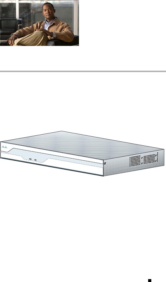
The Cisco 1841 router is a data-only device for desktop use.
Figure 2-1 shows the Cisco 1841 router.
Figure 2-1 The Cisco 1841 Router
SYS |
SYS |
PWR |
|
|
ACT |
Cisco 1800
Series
122331
The Cisco 1861 ISR, which is part of the Cisco 1800 series ISR family, is a unified communications solution for smallto medium-sized businesses and enterprise small branch offices that provides voice, data, voice-mail, automated attendant, video, and security capabilities while integrating with existing desktop applications such as calendar, e-mail, and customer relationship management (CRM) programs and with built-in security. It has the following core components:
•Integrated Cisco Unified Communications Manager Express or Survivable Remote Site Telephony for call processing for up to 12 users
•Optional Cisco Unity Express for voice messaging and automated attendant
•Integrated LAN switching with Power over Ethernet (POE) expandable via Cisco Catalyst Switches
•Optional support for a range of WAN interface cards
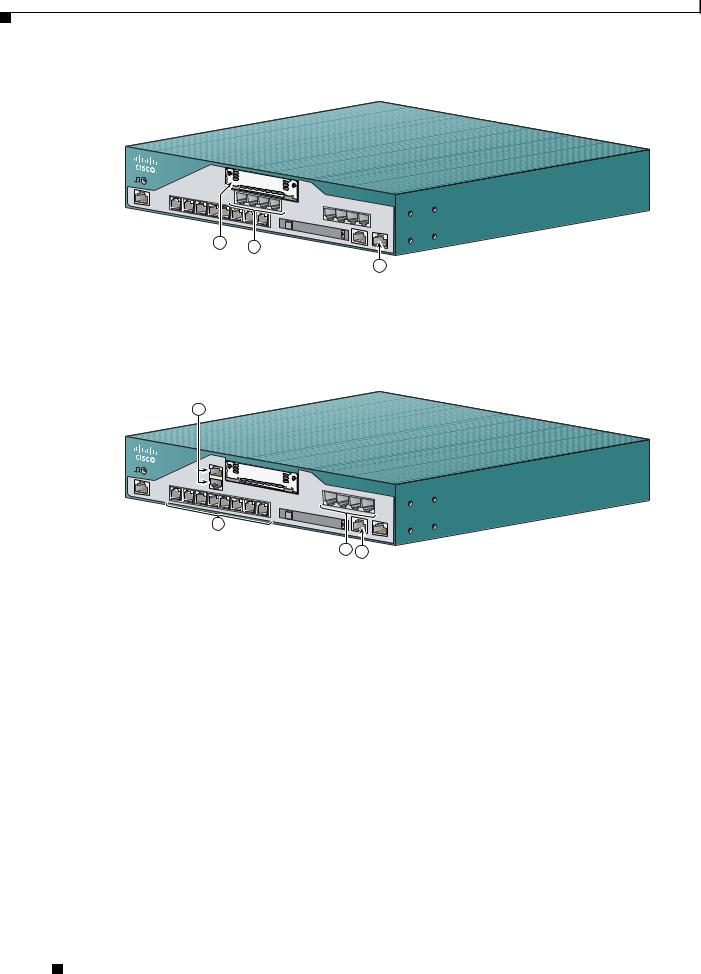
Figure 2-2 and Figure 2-3 show the Cisco 1861 ISR.
Cisco 1800 Series Routers (Modular) Hardware Installation Guide
|
OL-5876-03 |
2-1 |
|
|
|
Chapter 2 Overview of Cisco 1800 Series Routers (Modular)
Hardware Features
Figure 2-2 The Cisco 1861 Integrated Services Router with FXO Ports
 SYS
SYS
 POE
POE
 VM
VM
|
Cisco |
|
|
1800 |
Series |
|
|
|
1 |
2 |
|
|
|
3
231626
1 |
WAN slot |
|
3 |
Expansion switch port |
|
|
|
|
|
2 |
FXO ports |
|
|
|
|
|
|
|
|
Figure 2-3 |
The Cisco 1861 Integrated Services Router with BRI Ports |
|||
 SYS
SYS  POE
POE  VM
VM
1
1
00
2
Cisco |
|
1800 Se |
|
|
ries |
3 4
231625
1 |
BRI ports |
3 |
FXS ports |
|
|
|
|
2 |
Power over Ethernet (PoE) ports |
4 |
Fast Ethernet (FE) port |
|
|
|
|
This chapter describes the features and specifications of the router and includes the following sections:
•Hardware Features, page 2-2
•Chassis Views, page 2-8
•Interface Numbering, page 2-9
•Interface Numbering on the 1861 Integrated Services Router, page 2-10
•Specifications, page 2-11
•Regulatory Compliance, page 2-11
Hardware Features
This section describes the basic features of Cisco 1800 series routers. It contains the following:
• Product Serial Number Location, page 2-3
Cisco 1800 Series Routers (Modular) Hardware Installation Guide
2-2 |
OL-5876-03 |
|
|
Chapter 2 Overview of Cisco 1800 Series Routers (Modular)
Hardware Features
•Interfaces, page 2-3
•Removable and Interchangeable Modules, page 2-5
•Memory, page 2-5
•LED Indicators, page 2-6
•Chassis Ventilation, page 2-7
•Real-Time Clock, page 2-7
•Chassis Security, page 2-8
Product Serial Number Location
The serial number label for the Cisco 1841 router and the Cisco 1861 ISR is located on the rear of the chassis, underneath interface card slot 0. (See Figure 2-4.)
Figure 2-4 Serial Number Location
CISCO 1841
100-240 |
VAC- |
1 A |
|
50/60 |
Hz |
SN: AAANNNNXXXX
122334
SN: AAANNNNXXXX
Cisco Product Identification Tool
The Cisco Product Identification (CPI) tool provides detailed illustrations and descriptions showing where to locate serial number labels on Cisco products. It includes the following features:
•Search option allows browsing for models using a tree-structured product hierarchy.
•Search field on the final results page makes it easier to look up multiple products.
•End-of-sale products are clearly identified in results lists.
The tool streamlines the process of locating serial number labels and identifying products. Serial number information expedites the entitlement process and is important for access to support services.
The Cisco Product Identification tool can be accessed at the following URL:
http://tools.cisco.com/Support/CPI/index.do
Interfaces
This section summarizes the interfaces available on the Cisco 1800 series routers.
Cisco 1800 Series Routers (Modular) Hardware Installation Guide
|
OL-5876-03 |
2-3 |
|
|
|

Chapter 2 Overview of Cisco 1800 Series Routers (Modular)
Hardware Features
Interfaces on the Cisco 1841 Router
The following interfaces exist on the Cisco 1841 router:
•Two Fast Ethernet ports (RJ-45 connectors)
•High-speed console and auxiliary ports, up to 115.2 kbps each (RJ-45 connectors)
•One USB port (version 1.1), intended for future use
Interfaces on the Cisco 1861 Integrated Services Router
The Cisco 1861 Integrated Services Router comes with various possible configurations, based on built-in ports and other hardware features of the Cisco 1861 Integrated Services Router and organized by model.
Table 2-1 lists the labels and descriptions for the WAN, LAN, voice interface card (VIC), and other interfaces, along with the values for these interfaces in the preconfigured router software configuration.
Note In Table 2-1, all slots/ports are numbered right to left, unless otherwise noted.
Table 2-1 |
Cisco 1861 Integrated Services Router: Interfaces |
|
|
|
|
|
|
Description |
|
Label |
Value in Software Configuration |
|
|
|
|
Console/Aux port |
CONSOLE |
— |
|
|
|
|
|
Fast Ethernet 10/100 expansion |
EXPANSION |
FastEthernet0/1/8 |
|
port |
|
|
|
|
|
|
|
Fast Ethernet 10/100 WAN port |
WAN |
FastEthernet0/0 |
|
|
|
|
|
Fast Ethernet 10/100 Power over |
Power over Ethernet, and |
FastEthernet0/1/0 to 0/1/7 |
|
Ethernet (PoE) ports |
ACT 0 LNK to ACT 7 LNK |
|
|
|
|
|
|
FXS (Foreign Exchange Station) |
FXS, and |
port 0/0/0 to 0/0/3 |
|
ports |
|
0-3 |
|
|
|
|
|
FXO (Foreign Exchange Office) |
FXO, and |
port 0/1/0 to 0/1/3 |
|
ports |
|
0-3 |
|
|
|
|
|
ISDN BRI ports |
B0 - B1 |
Top-to-bottom, port 0/1/0 to |
|
|
|
|
0/1/1 |
|
|
|
|
VLAN number for data network |
— |
Vlan1 |
|
|
|
|
|
VLAN number for voice network |
— |
Vlan100 |
|
|
|
|
|
Music-on-Hold (MoH) port |
|
voice-port 0/4/0 |
|
|
|
|
|
Compact Flash slot |
COMPACT FLASH |
flash |
|
|
|
|
|
(Factory Option) VIC: BRI* |
VIC2-2BRI-NT/TE |
port 0/2/0 to 0/2/1 |
|
|
|
and 0-1 |
|
|
|
|
|
Cisco 1800 Series Routers (Modular) Hardware Installation Guide
2-4 |
OL-5876-03 |
|
|

Chapter 2 Overview of Cisco 1800 Series Routers (Modular)
Hardware Features
Table 2-1 |
Cisco 1861 Integrated Services Router: Interfaces |
|
||
|
|
|
|
|
Description |
|
Label |
|
Value in Software Configuration |
|
|
|
|
|
(Factory Option) VIC: FXO* |
VIC2-2FXO and 0-1 |
|
port 0/2/0 to 0/2/1 |
|
|
|
VIC2-4FXO and 0-3 |
|
or |
|
|
|
|
port 0/2/0 to 0/2/3 |
|
|
|
|
|
(Factory Option) VIC: FXS* |
VIC3-2FXS/DID and 0-1 |
|
port 0/2/0 to 0/2/1 |
|
|
|
VIC-4FXS/DID and 0-3 |
|
or |
|
|
VIC3-4FXS/DID and 0-3 |
|
port 0/2/0 to 0/2/3 |
|
|
|
|
|
* Only one optional VIC can be factory installed in a Cisco 1861 Integrated Services Router.
Removable and Interchangeable Modules
Various optional modules can be installed in the router to provide specific capabilities. These modules can be installed either by inserting them into slots on the chassis, or by opening the chassis and plugging them into connectors inside the chassis.
•Flash memory and interface cards fit into slots on the chassis and can be installed or removed without opening the chassis.
There are three types of interface cards for the 1800 series modular routers:
–WAN interface cards (WICs)
–Voice WAN interface cards (VWICs—in data mode only on the Cisco 1841)
–High-speed WAN interface cards (HWICs)
•The following components plug into connectors inside the chassis and can be installed or removed only by opening the chassis:
–Advanced integration module (AIM)
–Synchronous dynamic RAM (SDRAM) small-outline dual in-line memory module (SODIMM) Table 2-2 summarizes the optional modules:
Table 2-2 |
Summary of Cisco 1800 Series Removable and Interchangeable Modules |
||||
|
|
|
|
|
|
Model |
|
CompactFlash Memory |
Interface Cards |
AIMs |
SDRAM SODIMM |
|
|
|
|
|
|
Cisco 1841 |
|
1 |
2 single-wide cards |
1 |
1 |
|
|
|
|
|
|
Memory
Cisco 1800 series routers contain the following types of memory:
•SDRAM—Serves two functions. It stores the running configuration and routing tables, and it is used for packet buffering by the network interfaces. Cisco IOS software executes from SDRAM.
•Flash memory—Stores the operating system software image, configuration files, and log files. It is implemented in an external CompactFlash memory card.
Cisco 1800 Series Routers (Modular) Hardware Installation Guide
|
OL-5876-03 |
2-5 |
|
|
|

Chapter 2 Overview of Cisco 1800 Series Routers (Modular)
Hardware Features
•Boot/NVRAM—Serves two functions. It stores the ROM monitor, which allows you to boot an operating system software image from flash memory. It also stores the system configuration file and the virtual configuration register.
Table 2-3 lists the memory specifications for Cisco 1800 series routers.
Table 2-3 |
Router Memory Specifications for the Cisco 1841 Router |
|
|
|
|
Description |
|
Specification |
|
|
|
SDRAM |
|
128 MB, expandable to 384 MB; default is 128 MB |
|
|
|
Flash memory |
|
32, 64, or 128 MB; default is 32MB |
|
|
|
Boot/NVRAM |
|
2/4 MB flash memory |
|
|
|
Note SDRAM and the flash memory are user-upgradable, but the boot/NVRAM is permanently soldered to the router’s motherboard and is not upgradable.
Table 2-4 Router Memory Specifications for the Cisco 1861 ISR
Description |
Specification |
|
|
DRAM |
512 MB |
|
|
Flash memory |
128 MB |
|
|
LED Indicators
Table 2-5 summarizes the LED indicators for the Cisco 1841 router that are located in the router bezel or chassis, but not in the interface cards.
For descriptions of the LEDs in the interface cards, see Cisco Interface Card Installation Guide.
|
|
|
|
Table 2-5 |
Summary of Cisco 1800 Series LED Indicators |
|
|
||
|
|
|
|
|
|
|
|
|
|
|
|
|
|
LED |
|
Color |
Description |
Location: |
|
|
|
|
|
|
|
|
|
|
|
|
|
|
|
SYS PWR |
|
Green |
Router has successfully booted and the software is functional. |
Front |
|
|
|
|
|
|
|
|
This LED blinks while booting or in the ROM monitor. |
|
|
|
|
|
|
|
|
|
|
|
|
|
|
|
|
SYS ACT |
|
Green |
Blinking when any packets are transmitted or received on any |
Front |
|
|
|
|
|
|
|
|
WAN or LAN, or when monitoring system activity. |
|
|
|
|
|
|
|
|
|
|
|
|
|
|
|
|
CF |
|
Green |
On when flash memory is busy. Do not remove the CompactFlash |
Back |
|
|
|
|
|
|
|
|
memory card when this light is on. |
|
|
|
|
|
|
|
|
|
|
|
|
|
|
|
|
FDX (FE 0/0) |
|
Green |
On indicates full-duplex operation. Off indicates half-duplex |
Back |
|
|
|
|
|
|
|
|
operation. |
|
|
|
|
|
|
|
|
|
|
|
|
|
|
|
|
100 (FE 0/0) |
|
Green |
On indicates a 100-Mbps link. Off indicates a 10-Mbps link. |
Back |
|
|
|
|
|
|
|
|
|
|
|
|
|
|
|
Link (FE 0/0) |
|
Green |
On when the router is correctly connected to a local Ethernet |
Back |
|
|
|
|
|
|
|
|
LAN through Ethernet port 0. |
|
|
|
|
|
|
|
|
|
|
|
|
|
|
|
|
FDX (FE 0/1) |
|
Green |
On indicates full-duplex operation. Off indicates half-duplex |
Back |
|
|
|
|
|
|
|
|
operation. |
|
|
|
|
|
|
|
|
|
|
|
|
|
|
|
Cisco 1800 Series Routers (Modular) Hardware Installation Guide |
|
|
||||
|
|
|
|
|
|||||
|
2-6 |
|
|
|
|
|
|
OL-5876-03 |
|
|
|
|
|
|
|
|
|
||
Chapter 2 Overview of Cisco 1800 Series Routers (Modular)
Hardware Features
Table 2-5 |
Summary of Cisco 1800 Series LED Indicators (continued) |
|
||
|
|
|
|
|
LED |
|
Color |
Description |
Location: |
|
|
|
|
|
100 (FE 0/1) |
|
Green |
On indicates a 100-Mbps link. Off indicates a 10-Mbps link. |
Back |
|
|
|
|
|
Link (FE 0/1) |
|
Green |
On when the router is correctly connected to a local Ethernet |
Back |
|
|
|
LAN through Ethernet port 1. |
|
|
|
|
|
|
AIM |
|
Green |
On indicates presence of an AIM in the internal AIM slot. |
Back |
|
|
|
|
|
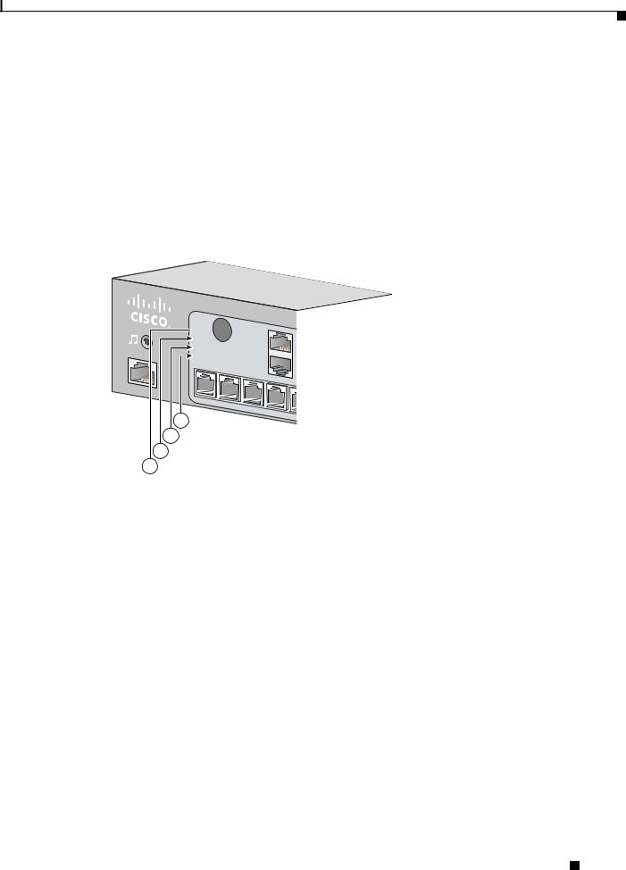
Figure 2-5 summarizes the LED indicators for the Cisco 1861 ISR that are located in the router bezel.
Figure 2-5 LEDs on the Front Panel of the Cisco 1861 Integrated Services Router
 SYS
SYS 
 POE
POE 
 VM
VM 
 WLAN
WLAN
1
4
3
2
1
230870
1 |
SYS |
Solid green |
Online |
|
|
|
|
2 |
POE |
Solid green |
Connected |
|
|
|
|
3 |
VM |
Solid green |
Online |
|
|
|
|
4 |
WLAN |
Blinking green |
Connected |
|
|
|
|
Chassis Ventilation
An internal three-speed fan provides chassis cooling. An onboard temperature sensor controls the fan speed. The fan is always on when power is applied to the router. Under most conditions, the fan operates at the slowest speed to conserve power and reduce fan noise. It operates at the higher speeds when necessary under conditions of higher ambient temperature.
Real-Time Clock
An internal real-time clock with battery backup provides the system software with time of day on system power up. This allows the system to verify the validity of a certification authority (CA) certificate. The backup battery is a socketed lithium battery. This battery lasts the life of the router under the operating environmental conditions specified for the router, and is not field replaceable.
Cisco 1800 Series Routers (Modular) Hardware Installation Guide
|
OL-5876-03 |
2-7 |
|
|
|

Chapter 2 Overview of Cisco 1800 Series Routers (Modular)
Chassis Views
Note If the lithium battery in a Cisco 1841 router should fail, the router must be returned to Cisco for repair. Do not replace the battery yourself. Although the battery is not intended to be field replaceable, the safety agencies require the following warning be included in this document.
Warning There is the danger of explosion if the battery is replaced incorrectly. Replace the battery only with the same or equivalent type recommended by the manufacturer. Dispose of used batteries according to the manufacturer’s instructions. Statement 1015
Chassis Security
The chassis of the Cisco 1841 router is constructed with a KensingtonTM security slot on the back panel. It can be secured to a desktop or other surface by using KensingtonTM lockdown equipment.
Chassis Views
This section contains views of the front and rear panels of Cisco 1841 router, showing the locations of the power and signal interfaces, the interface card slots, and the status indicators.
Figure 2-6 shows the front panel of a Cisco 1841 router. Figure 2-7 shows the back panel.
Figure 2-6 Front Panel of the Cisco 1841 Router
SYS |
SYS |
PWR |
ACT |
1 2
Cisco 1800 Series
122329
1 |
System Power (SYS PWR) LED |
2 |
System Activity (SYS ACT) LED |
|
|
|
|
Figure 2-7 |
Back Panel of the Cisco 1841 Router |
|
|
|||
7 |
6 |
5 |
4 |
3 |
2 |
1 |
SLOT 1 |
|
FE 0/1 |
CONSOLE |
SLOT 0 |
CISCO 1841 |
|
|
|
|
|
100-240 VAC- |
|
|
FDX |
|
|
1 A |
|
|
100 |
|
|
50/60 Hz |
|
|
LINK |
|
|
|
|
|
FDX |
|
|
|
|
|
100 |
|
|
|
|
|
LINK |
|
|
|
CF |
AIM |
FE 0/0 |
AUX |
|
|
DO NOT REMOVE DURING NETWORK OPERATION |
|
|
|
||
|
|
|
|
|
8 |
8 |
9 |
5 |
12 |
13 |
122330 |
|
|
|
11 |
|
|
|
|
|
|
10 |
|
|
|
Cisco 1800 Series Routers (Modular) Hardware Installation Guide
2-8 |
OL-5876-03 |
|
|

Chapter 2 Overview of Cisco 1800 Series Routers (Modular)
Interface Numbering
1 |
Input power connection |
8 |
CompactFlash memory card slot |
|
|
|
|
2 |
On/Off switch |
9 |
CompactFlash (CF) LED |
|
|
|
|
3 |
Slot 0 (WIC, VWIC—data only, or HWIC) |
10 |
AIM LED |
|
|
|
|
4 |
Console port |
11 |
USB port |
|
|
|
|
5 |
Fast Ethernet ports and LEDs |
12 |
Aux port |
|
|
|
|
6 |
KensingtonTM security slot |
13 |
Chassis ground connection |
7 |
Slot 1 (WIC, VWIC—data only, or HWIC) |
|
|
|
|
|
|
Interface Numbering
Each individual interface (port) on a Cisco 1841 router is identified by a number. A Cisco 1841 router contains the following wide-area network (WAN) and local-area network (LAN) interface types:
•Two onboard Fast Ethernet LAN interfaces
•Two slots in which you can install WICs, VWICs (data only), and HWICs.
The numbering format for the slots is interface-type 0/slot-number/interface-number. Table 2-6 summarizes the interface numbering.
Table 2-6 |
Interface Numbering |
|
|
|
|
|
|
|
|
Slot Number |
|
Slot Type |
Slot Numbering Range |
Example1 |
Onboard Ports |
|
Fast Ethernet |
0/0 and 0/1 |
interface fastethernet 0/0 |
|
|
|
|
|
Slot 0 |
|
HWIC/WIC/VWIC2 |
0/0/0 to 0/0/3 |
interface serial 0/0/0 |
|
|
|
|
line async 0/0/0 |
|
|
|
|
|
Slot 1 |
|
HWIC/WIC/VWIC2 |
0/1/0 to 0/1/3 |
interface serial 0/1/0 |
|
|
|
|
line async 0/1/0 |
|
|
|
|
|
1.The interfaces listed are examples only; other possible interface types are not listed.
2.VWICs are data-only in a Cisco 1841 router.
Note On the Cisco 1841 router, the numbering format for configuring an async interface is 0/slot/port. To configure the line associated with an async interface, simply use the interface number to specify the async line. For example, line 0/0/0 specifies the line associated with interface serial 0/0/0 on a WIC-2A/S in slot 0. Similarly, line 0/1/1 specifies the line associated with interface async 0/1/1 on a WIC-2AM in slot 1.
Cisco 1800 Series Routers (Modular) Hardware Installation Guide
|
OL-5876-03 |
2-9 |
|
|
|

Chapter 2 Overview of Cisco 1800 Series Routers (Modular)
Interface Numbering on the 1861 Integrated Services Router
Interface Numbering on the 1861 Integrated Services Router
Each interface (port) on a Cisco 1861 ISR is identified by a number. The Cisco 1861 router contains the following WANLAN interface types:
•One onboard Fast Ethernet LAN interface (FastEthernet0/0)
•One onboard Ethernet switch
•One fixed VIC slot with 4 FXS ports
•One fixed VIC slot with 4 FXO or 2 BRI ports
•One modular HWIC/WIC/VWIC slot
The numbering format for the slots is interface-type 0/slot-number/port-number. Table 2-7 summarizes the interface numbering.
Table 2-7 |
Interface Numbering |
|
|
|
|
|
|
|
|
Slot Number |
|
Slot Type |
Slot Numbering Range |
Example1 |
Onboard Ports |
|
Fast Ethernet |
0/0 |
interface fastethernet 0/0 |
|
|
|
|
|
Onboad Slot 1 |
|
Fast Ethernet Switch |
0/1/0 to 0/1/7 |
interface fastethernet 0/1/0 |
|
|
|
|
|
Fixed HWIC slot 0 |
FXS |
0/0/0 to 0/0/3 |
voice-port 0/0/0/ |
|
|
|
|
|
|
Fixed HWIC slot 1 |
FXO |
0/1/0 to 0/1/3 |
voice-port 0/1/0 |
|
|
|
|
|
|
|
|
BRI |
0/1/0 to 0/1/1 |
|
|
|
|
|
|
Modular HWIC Slot |
HWIC/WIC/VWIC |
0/3/0 to 0/3/x, where x |
interface serial 0/0/0 |
|
|
|
|
depends on the |
|
|
|
|
card-type. |
|
|
|
|
|
|
1. The interfaces listed are examples only; other possible interface types are not listed.
Note On the Cisco 1861 ISR, the numbering format for configuring an asynchronous, or async, interface is 0/slot/port. To configure the line associated with an async interface, simply use the interface number to specify the async line. For example, line 0/0/0 specifies the line associated with interface serial 0/0/0 on a WIC-2A/S in slot 0. Similarly, line 0/1/1 specifies the line associated with interface async 0/1/1 on a WIC-2AM in slot 1.
Note If you have specified the use of a private line automatic ringdown (PLAR) off-premises extension (OPX) connection mode for an FXO voice port (with loop resistance less than 8000 Ohm), you must ensure that the soft-offhook option is enabled on the port.
This option allows a stepped offhook resistance during seizure, which avoids overloading the circuit during offhook in the event that ringing voltage is present on the circuit at the same time as the trunk seizure. The stepped offhook resistance is initially set to 800 Ohms, then adjusts to 50 Ohms when ringing voltage is not present.
To enable the soft-offhook command on the port, and to access the connection command with plar opx syntax, see Cisco Command Lookup Tool.
Cisco 1800 Series Routers (Modular) Hardware Installation Guide
2-10 |
OL-5876-03 |
|
|

Chapter 2 Overview of Cisco 1800 Series Routers (Modular)
Specifications
Specifications
Table 2-8 lists the specifications for Cisco 1800 series routers.
Table 2-8 1841 Router Specifications
Description |
Specification |
|
|
Dimensions without rubber feet |
1.73 x 13.5 x 10.8 in. (4.4 x 34.3 x 27.4 cm) |
(H x W x D) |
|
|
With rubber feet, height is 1.87 in. (4.75 cm) |
|
|
Weight (no modules installed) |
6.1 lb. (2.77 kg) |
|
|
Input voltage, AC power supply |
100 to 240 VAC, autoranging |
Frequency |
47 to 63 Hz |
|
|
Power consumption |
20 W maximum for an unloaded unit. |
|
With two WICs and an AIM installed, power consumption will be |
|
less than 50 W. |
|
|
Console and auxiliary ports |
RJ-45 connectors |
|
|
Operating humidity |
5 to 95%, noncondensing |
|
|
Operating temperature |
32 to 104°F (0 to 40°C) |
|
|
Nonoperating temperature shock |
–13 to 158°F (–25 to 70°C) at 9° F (5° C)/minute minimum |
|
|
Noise level |
Normal operating temperature (< 78° F or 26° C): 34 dBa |
|
From (78° F or 26° C) through (104° F or 40° C): 37 dBa |
|
>104° F or 40° C: 42 dBa |
|
|
Regulatory compliance |
For detailed regulatory compliance information, see |
|
Regulatory Compliance and Safety Information for Cisco 1840 |
|
Routers, which accompanies the router. |
|
|
Electromagnetic compatibility |
FCC Part 15 Class A. |
|
|
Safety compliance |
UL 60950; CSA 60950; IEC 60950; EN 60950; AS/NZS 3260; |
|
NOM-019-SCFI-1998. |
|
|
Regulatory Compliance
For compliance information, see Regulatory Compliance and Safety Information for Cisco 1840 Routers document that accompanies the router.
Cisco 1800 Series Routers (Modular) Hardware Installation Guide
|
OL-5876-03 |
2-11 |
|
|
|

Chapter 2 Overview of Cisco 1800 Series Routers (Modular)
Regulatory Compliance
Cisco 1800 Series Routers (Modular) Hardware Installation Guide
2-12 |
OL-5876-03 |
|
|
Loading...