


 Loading...
Quick Start Guide
Cisco 1811 and 1812 Integrated Services Router Cabling and
Installation
INCLUDING LICENSE AND WARRANTY
1Cisco One-Year Limited Hardware Warranty Terms
2Overview
3Unpacking the Box
4Connecting the Router
5Connecting Antennas to the Router RP-TNC Connectors
6Configuring the Router Using Cisco Router and Security Device Manager
7Connecting a PC to the Router Console Port
8Verifying Your Installation
9Obtaining Documentation
10Cisco Product Security Overview
11Obtaining Technical Assistance
12Obtaining Additional Publications and Information
Note: For localized versions of these instructions, please see the following URL:
http://www.cisco.com/univercd/cc/td/doc/product/access/acs_mod/1800fix/qsgs/index.htm

1 Cisco One-Year Limited Hardware Warranty Terms
There are special terms applicable to your hardware warranty and various services that you can use during the warranty period. Your formal Warranty Statement, including the warranty applicable to Cisco software, is included on the CD that accompanies your Cisco product. Follow these steps to access and download the Cisco Information Packet and your warranty document from the CD or from Cisco.com.
1.Launch your browser, and go to this URL: http://www.cisco.com/univercd/cc/td/doc/es_inpck/cetrans.htm
The Warranties and License Agreements page appears.
2.To read the Cisco Information Packet, follow these steps:
a.Click the Information Packet Number field, and make sure that the part number 78-5235-02F0 is highlighted.
b.Select the language in which you would like to read the document.
c.Click Go.
The Cisco Limited Warranty and Software License page from the Information Packet appears.
d.Read the document online, or click the PDF icon to download and print the document in Adobe Portable Document Format (PDF).
Note You must have Adobe Acrobat Reader to view and print PDF files. You can download the reader from Adobe’s website: http://www.adobe.com
3.To read translated and localized warranty information about your product, follow these steps:
a.Enter this part number in the Warranty Document Number field: 78-10747-01C0
b.Select the language in which you would like to view the document.
c.Click Go.
The Cisco warranty page appears.
d.Read the document online, or click the PDF icon to download and print the document in Adobe Portable Document Format (PDF).
You can also contact the Cisco service and support website for assistance:
http://www.cisco.com/en/US/support/.
Duration of Hardware Warranty
One (1) Year
Replacement, Repair, or Refund Policy for Hardware
Cisco or its service center will use commercially reasonable efforts to ship a replacement part within ten (10) working days after receipt of a Return Materials Authorization (RMA) request. Actual delivery times can vary, depending on the customer location.
Cisco reserves the right to refund the purchase price as its exclusive warranty remedy.
To Receive a Return Materials Authorization (RMA) Number
Contact the company from whom you purchased the product. If you purchased the product directly from Cisco, contact your Cisco Sales and Service Representative.
2
Complete the information below, and keep it for reference.
Company product purchased from
Company telephone number
Product model number
Product serial number
Maintenance contract number
2 Overview
This document describes the steps for installing the Cisco 1811 and the Cisco 1812 integrated services routers. The Cisco 1811 and Cisco 1812 routers are fixed-configuration routers. They each include an integrated 8-port 10/100-Mbps Ethernet switch, two onboard Fast Ethernet WAN ports, two dual USB 2.0 ports, and optional 802.11a/b/g wireless LAN support. The switch ports and the onboard 10/100-Mbps Ethernet ports support 802.1Q virtual LAN (VLAN) encapsulation and enable you to configure demilitarized zones (DMZs), using VLANs and Cisco IOS firewall features. The switch ports are also optionally upgradable to include inline power support for IP phones.
The Cisco 1811 and Cisco 1812 integrated services routers provide secure Internet connectivity and dial backup if your primary connection fails. The Cisco 1811 router provides dial backup through a V.92 analog modem port. The Cisco 1812 router provides dial backup through an ISDN S/T port.
Additional documentation can be found on Cisco.com.
Product Serial Number Location
The serial number label for the Cisco 1811 and Cisco 1812 routers is located on the back of the chassis, above and to the right of the power switch. You need this serial number when calling Cisco for support. To see specifically where the serial label is on your router, go to the following link:
http://tools.cisco.com/Support/CPI/index.do
3 Unpacking the Box
When you unpack the box containing your Cisco 1811 or Cisco 1812 router, you should find the items shown in Figure 1.
Note The Cisco 1811 and Cisco 1812 routers have a wireless upgradable option. If this option is chosen, an antenna kit should have been shipped with your router in addition to the items listed in Figure 1.
3
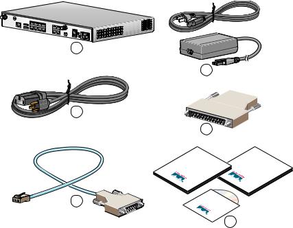
Figure 1 Items Included with the Cisco 1811 and Cisco 1812 Integrated Services Router
1
2
3
4
5
Guide Start |
Documentation |
Quick |
Other |
CD- |
|
ROM |
|
6
121550
1 |
Cisco 1811 or Cisco 1812 router |
4 |
PoE power supply and cable (optional) |
|
|
|
|
2 |
Power cable |
5 |
DB-9 to DB-25 adapter |
|
|
|
|
3 |
Console cable (light blue, RJ-45 to DB-9) |
6 |
Product documentation |
|
|
|
|
The shipment should include the following items:
•One Cisco 1811 router or one Cisco 1812 router
•One blue RJ-45-to-DB-9 console cable
•One DB-9-to-DB-25 adapter
•One black power supply cord
•One Power over Ethernet (PoE) power supply, if the router was purchased with the PoE option
•Product documentation
•One CD-ROM containing Cisco Router and Security Device Manager (SDM)
•One antenna kit (optional)
Items You Need to Provide
Depending on your network environment, you may need to provide some of the following items so that you can install the router:
•Straight-through Ethernet cables (RJ-45-to-RJ-45) to connect the router to a broadband (xDSL or cable) modem and to a hub or switch
•Ethernet hub or switch to connect the router to the local network, or an xDSL or cable modem to connect the router to the service provider
•Server or other computer with a network interface card (NIC) or other networked device (such as a hub or a switch) to connect to the integrated 8-port 10/100-Mbps Ethernet switch
4

4 Connecting the Router
Figure 2 shows a typical installation of a Cisco 1811 or Cisco 1812 router.
Figure 2 Typical Installation of a Cisco 1811 or Cisco 1812 Router
1
2
Ethernet Hub |
5 |
|
3 |
Internet Service
4 |
Provider |
DSL/Cable Modem
PC
121549
Follow these steps to connect the router to the power supply, your local network, and your service provider network:
Step 1 Connect power to the router as shown in Figure 2:
a.Connect the separate power cord to the power socket on the back panel of the router.
b.Connect the other end of the separate power cord to a power outlet.
Note If you have a router with the PoE option, you must connect the PoE power supply to the PoE socket on the back of the router, connect the female end of the PoE power cable to the PoE power supply, and connect the male end of the PoE power cable to a power outlet.
c.Turn on the router by pressing the power switch to the on ( | ) position.
d.Confirm that the router has power by checking that the SYS OK LED on the front panel is on.
Step 2 To connect the router to your network, connect one end of an Ethernet cable (RJ-45) to an Ethernet switch port (FE 2–FE 9), and connect the other end of the cable to a port on a hub or switch, as shown in Figure 2.
Note The example in Figure 2 shows connectivity to a hub. The router Ethernet switch ports can be connected to another networked device, such as a switch or computer with a network interface card (NIC). If you are connecting a computer to the switch port on the router, it will take about 30 seconds for connectivity to be established.
5

Step 3 To use Cisco Router and Security Device Manager (SDM) to configure your router, you must connect a PC to the first Ethernet switch port. Connect one end of an Ethernet cable to one of the Ethernet switch ports (FE 2–FE 9), and connect the other end to the Ethernet port on your PC.
Caution Always connect the Ethernet cable to an Ethernet port on the router. Accidentally connecting the cable to the wrong port can damage your router.
Step 4 To connect the router to your service provider network, connect one end of an Ethernet cable to a 10/100 Fast Ethernet port (these ports are labeled FE 0 and FE 1); connect the other end of the cable to a network port on your service provider’s broadband (xDSL or cable) modem equipment, as shown in Figure 2.
Caution Always connect the Ethernet cable to an Ethernet port on the router. Accidentally connecting the cable to the wrong port can damage your router.
Step 5 (Optional) The Cisco 1811 router supports a 230-kbps dialup connection to your service provider network through its V.92 modem port. The Cisco 1812 router supports a 144-kbps dialup connection to your service provider network through its ISDN S/T port. These connections can serve as a backup to your service provider if your primary connection goes down. To make a backup connection to your service provider network, connect one end of a straight-through RJ-11 cable to the V.92 modem port (for the Cisco 1811) or a straight-through RJ45 cable to the ISDN S/T port (for the Cisco 1812) on the router, as shown in Figure 2, and connect the other end of the cable to your telephone wall jack.
Note To configure your router for a backup dialup connection, you must use the Cisco IOS command-line interface (CLI). For more information, see the Cisco 1800 Series Integrated Services Routers (Fixed) Software Configuration Guide.
5 Connecting Antennas to the Router RP-TNC Connectors
If your router has the wireless LAN option, connect the antennas by screwing the antenna connectors in a clockwise direction onto the reverse-polarity threaded Neill-Concelman (RP-TNC) connectors on the back panel of the router. Figure 3 shows an example of how to connect the swivel-mount dipole antennas to the router.
Note The location and position of your router antennas are crucial to effective wireless connectivity. For more information about the antennas compatible with the Cisco 1801, Cisco 1802, and Cisco 1803 routers, see the online documents located at the following URL: http://www.cisco.com/univercd/cc/td/doc/product/access/acs_mod/1800fix/antennas/index.htm
6
Loading...