


 Loading...
OSPF Sham-Link Support for MPLS VPN
Feature History
Release |
Modification |
12.2(8)T |
This feature was introduced. |
|
|
This document describes how to configure and use a sham-link to connect Virtual Private Network (VPN) client sites that run the Open Shortest Path First (OSPF) protocol and share backdoor OSPF links in a Multiprotocol Label Switching (MPLS) VPN configuration.
This document includes the following sections:
•Feature Overview, page 1
•Supported Platforms, page 8
•Supported Standards, MIBs, and RFCs, page 10
•Prerequisites, page 10
•Configuration Tasks, page 10
•Configuration Examples, page 12
•Command Reference, page 12
•Glossary, page 16
Feature Overview
Using OSPF in PE-CE Router Connections
In an MPLS VPN configuration, the OSPF protocol is one way you can connect customer edge (CE) routers to service provider edge (PE) routers in the VPN backbone. OSPF is often used by customers that run OSPF as their intrasite routing protocol, subscribe to a VPN service, and want to exchange routing information between their sites using OSPF (during migration or on a permanent basis) over an MPLS VPN backbone.
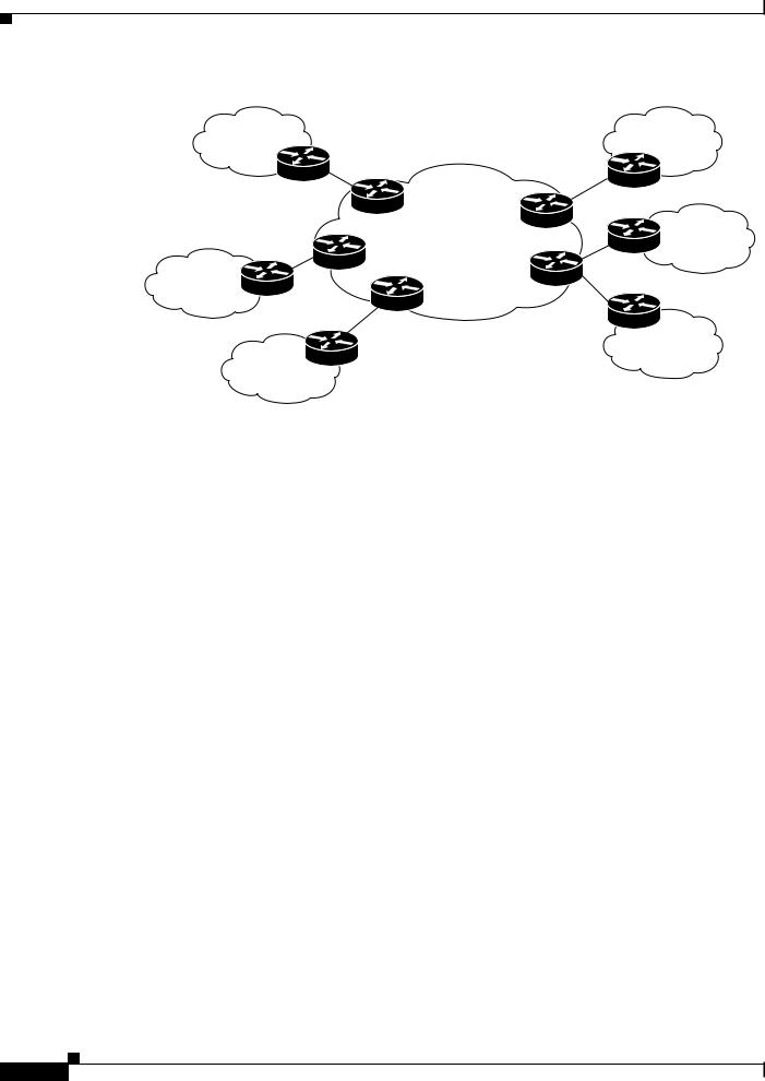
Figure 1 shows an example of how VPN client sites that run OSPF can connect over an MPLS VPN backbone.
Cisco IOS Release 12.2(8)T
1
OSPF Sham-Link Support for MPLS VPN
Feature Overview
Figure 1 OSPF Connectivity Between VPN Client Sites and an MPLS VPN Backbone
Area 1 |
Area 1 |
MPLS VPN |
Area 2 |
|
Superbackbone |
||
|
Area 0
Area 0
Area 3
70390
When OSPF is used to connect PE and CE routers, all routing information learned from a VPN site is placed in the VPN routing and forwarding (VRF) instance associated with the incoming interface. The PE routers that attach to the VPN use the Border Gateway Protocol (BGP) to distribute VPN routes to each other. A CE router can then learn the routes to other sites in the VPN by peering with its attached PE router. The MPLS VPN superbackbone provides an additional level of routing hierarchy to interconnect the VPN sites running OSPF.
When OSPF routes are propagated over the MPLS VPN backbone, additional information about the prefix in the form of BGP extended communities (route type, domain ID extended communities) is appended to the BGP update. This community information is used by the receiving PE router to decide the type of link-state advertisement (LSA) to be generated when the BGP route is redistributed to the OSPF PE-CE process. In this way, internal OSPF routes that belong to the same VPN and are advertised over the VPN backbone are seen as interarea routes on the remote sites.
For basic information about how to configure an MPLS VPN, refer to:
http://www.cisco.com/univercd/cc/td/doc/product/software/ios120/120newft/120t/120t5/vpn.htm
Using a Sham-Link to Correct OSPF Backdoor Routing
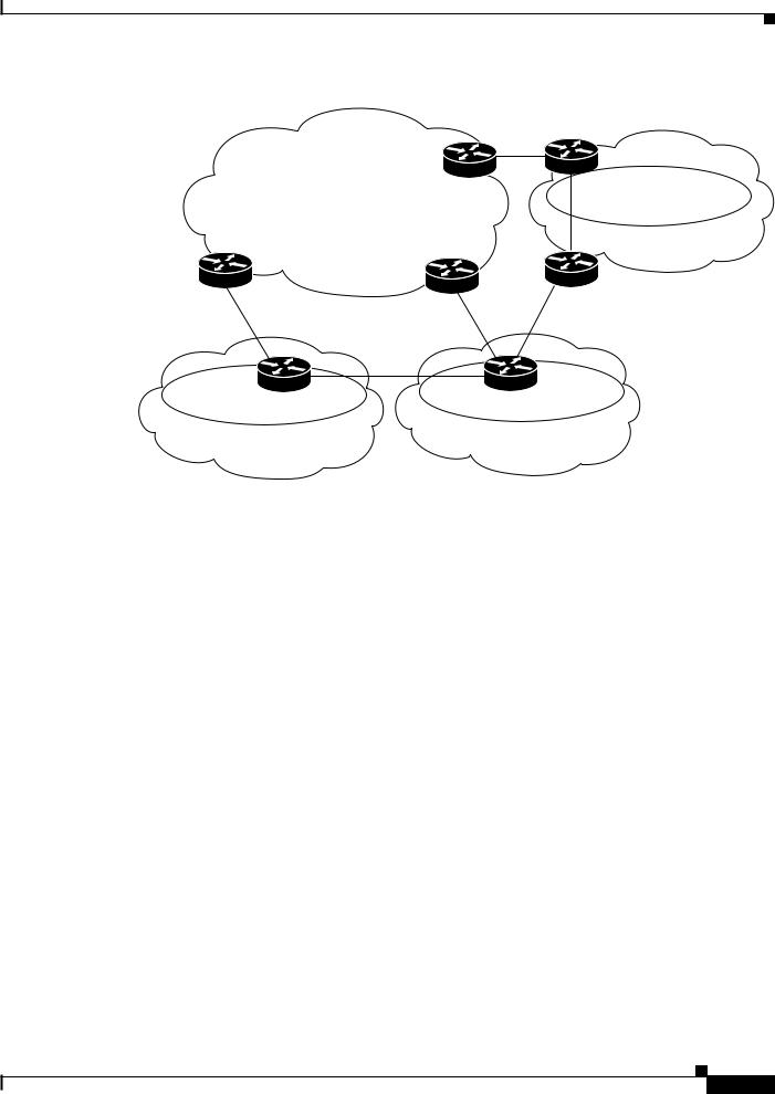
Although OSPF PE-CE connections assume that the only path between two client sites is across the MPLS VPN backbone, backdoor paths between VPN sites (shown in grey in Figure 2) may exist. If these sites belong to the same OSPF area, the path over a backdoor link will always be selected because OSPF prefers intraarea paths to interarea paths. (PE routers advertise OSPF routes learned over the VPN backbone as interarea paths.) For this reason, OSPF backdoor links between VPN sites must be taken into account so that routing is performed based on policy.
Cisco IOS Release 12.2(8)T
2
OSPF Sham-Link Support for MPLS VPN
Feature Overview
Figure 2 |
Backdoor Paths Between OSPF Client Sites |
|
|
|
|
MPLS VPN Backbone |
|
|
|
|
|
PE-3 |
Winchester |
|
|
|
10.3.1.7 |
Area 1 |
|
|
|
10.3.1.2 |
||
|
|
|
|
|
|
PE-1 |
PE-2 |
Brighton |
|
|
10.3.1.6 |
|
|
|
|
|
10.3.1.5 |
|
|
70391
Area 1 |
Vienna |
Stockholm |
Area 1 |
|
|
||
|
10.3.1.15 |
10.3.1.3 |
|
For example, Figure 2 shows three client sites, each with backdoor links. Because each site runs OSPF within the same Area 1 configuration, all routing between the three sites follows the intraarea path across the backdoor links, rather than over the MPLS VPN backbone.
The following example shows BGP routing table entries for the prefix 10.3.1.7/32 in the PE-1 router in Figure 2. This prefix is the loopback interface of the Winchester CE router. As shown in bold in this example, the loopback interface is learned via BGP from PE-2 and PE-3. It is also generated through redistribution into BGP on PE-1.
PE-1# show ip bgp vpnv4 all 10.3.1.7
BGP routing table entry for 100:251:10.3.1.7/32, version 58 Paths: (3 available, best #2)
Advertised to non peer-group peers: 10.3.1.2 10.3.1.5
Local
10.3.1.5 (metric 30) from 10.3.1.5 (10.3.1.5)
Origin incomplete, metric 22, localpref 100, valid, internal Extended Community: RT:1:793 OSPF DOMAIN ID:0.0.0.100 OSPF RT:1:2:0 OSPF 2
Local
10.2.1.38 from 0.0.0.0 (10.3.1.6)
Origin incomplete, metric 86, localpref 100, weight 32768, valid, sourced, best
Extended Community: RT:1:793 OSPF DOMAIN ID:0.0.0.100 OSPF RT:1:2:0 OSPF 2
Local
10.3.1.2 (metric 30) from 10.3.1.2 (10.3.1.2)
Origin incomplete, metric 11, localpref 100, valid, internal Extended Community: RT:1:793 OSPF DOMAIN ID:0.0.0.100 OSPF RT:1:2:0 OSPF 2
Within BGP, the locally generated route (10.2.1.38) is considered to be the best route. However, as shown in bold in the next example, the VRF routing table shows that the selected path is learned via OSPF with a next hop of 10.2.1.38, which is the Vienna CE router.
Cisco IOS Release 12.2(8)T
3

OSPF Sham-Link Support for MPLS VPN
Feature Overview
PE-1# show ip route vrf ospf 10.3.1.7
Routing entry for 10.3.1.7/32
Known via "ospf 100", distance 110, metric 86, type intra area Redistributing via bgp 215
Advertised by bgp 215
Last update from 10.2.1.38 on Serial0/0/0, 00:00:17 ago Routing Descriptor Blocks:
* 10.2.1.38, from 10.3.1.7, 00:00:17 ago, via Serial0/0/0 Route metric is 86, traffic share count is 1
This path is selected because:
•The OSPF intra-area path is preferred over the interarea path (over the MPLS VPN backbone) generated by the PE-1 router.
•OSPF has a lower administrative distance (AD) than internal BGP (BGP running between routers in the same autonomous system).
If the backdoor links between sites are used only for backup purposes and do not participate in the VPN service, then the default route selection shown in the preceding example is not acceptable. To reestablish the desired path selection over the MPLS VPN backbone, you must create an additional OSPF intra-area (logical) link between ingress and egress VRFs on the relevant PE routers. This link is called a sham-link.
A sham-link is required between any two VPN sites that belong to the same OSPF area and share an OSPF backdoor link. If no backdoor link exists between the sites, no sham-link is required.
Figure 3 shows a sample sham-link between PE-1 and PE-2. A cost is configured with each sham-link and is used to decide whether traffic will be sent over the backdoor path or the sham-link path. When a sham-link is configured between PE routers, the PEs can populate the VRF routing table with the OSPF routes learned over the sham-link.
Cisco IOS Release 12.2(8)T
4

OSPF Sham-Link Support for MPLS VPN
Feature Overview
Figure 3 Using a Sham-Link Between PE Routers to Connect OSPF Client Sites
|
MPLS VPN Backbone |
|
|
|
|
|
|
|
Net=10.3.1.7 |
PE-3 |
|
|
Winchester |
|
|
|
Route-type 1:2:0 |
|
|
|
|||
|
|
|
10.3.1.7 |
Area 1 |
|||
|
|
10.3.1.2 |
|
||||
|
|
|
Net=10.3.1.7 |
|
|||
|
|
|
|
|
|
|
|
|
Net=10.3.1.7 |
|
|
|
|
Type-1 LSA |
|
|
|
|
|
|
Brighton |
|
|
|
MP-BGP Route-type 1:2:0 |
|
|
|
|
||
|
|
|
|
|
|
||
|
Net=10.3.1.7 |
|
|
|
|
|
|
PE-1 |
Sham-link Type-1 LSA |
PE-2 |
|
|
|
|
|
|
|
|
Net=10.3.1.7 |
|
|||
10.3.1.6 |
|
10.3.1.5 |
|
|
|
||
|
|
|
|
|
Type-1 LSA |
|
|
Area 1 |
Vienna |
|
Stockholm |
Area 1 |
|
||
|
|
|
|
||||
|
10.3.1.15 |
|
|
10.3.1.3 |
|
|
|
70392
Because the sham-link is seen as an intra-area link between PE routers, an OSPF adjacency is created and database exchange (for the particular OSPF process) occurs across the link. The PE router can then flood LSAs between sites from across the MPLS VPN backbone. As a result, the desired intra-area connectivity is created.
The section, “ Creating a Sham-Link”, describes how to configure a sham-link between two PE routers. For more information about how to configure OSPF, refer to:
http://www.cisco.com/univercd/cc/td/doc/product/software/ios120/12cgcr/np1_c/1cprt1/1cospf.htm
Sham-Link Configuration Example
The example in this section is designed to show how a sham-link is used only to affect the OSPF intra-area path selection of the PE and CE routers. The PE router also uses the information received from MP-BGP to set the outgoing label stack of incoming packets, and to decide to which egress PE router to label switch the packets.
Figure 4 shows a sample MPLS VPN topology in which a sham-link configuration is necessary. A VPN client has three sites, each with a backdoor link. Two sham-links have been configured, one between PE-1 and PE-2, and another between PE-2 and PE-3. A sham-link between PE-1 and PE-3 is not necessary in this configuration because the Vienna and Winchester sites do not share a backdoor link.
Cisco IOS Release 12.2(8)T
5
Loading...