


 Loading...
Cisco AC/DC Power System User Guide
Release 1.0
Last Updated: May 15, 2005
Corporate Headquarters
Cisco Systems, Inc. 170 West Tasman Drive
San Jose, CA 95134-1706 USA http://www.cisco.com Tel: 408 526-4000
800 553-NETS (6387) Fax: 408 526-4100
Text Part Number: 78-16641-02
THE SPECIFICATIONS AND INFORMATION REGARDING THE PRODUCTS IN THIS MANUAL ARE SUBJECT TO CHANGE WITHOUT NOTICE. ALL STATEMENTS, INFORMATION, AND RECOMMENDATIONS IN THIS MANUAL ARE BELIEVED TO BE ACCURATE BUT ARE PRESENTED WITHOUT WARRANTY OF ANY KIND, EXPRESS OR IMPLIED. USERS MUST TAKE FULL RESPONSIBILITY FOR THEIR APPLICATION OF ANY PRODUCTS.
THE SOFTWARE LICENSE AND LIMITED WARRANTY FOR THE ACCOMPANYING PRODUCT ARE SET FORTH IN THE INFORMATION PACKET THAT SHIPPED WITH THE PRODUCT AND ARE INCORPORATED HEREIN BY THIS REFERENCE. IF YOU ARE UNABLE TO LOCATE THE SOFTWARE LICENSE OR LIMITED WARRANTY, CONTACT YOUR CISCO REPRESENTATIVE FOR A COPY.
The following information is for FCC compliance of Class A devices: This equipment has been tested and found to comply with the limits for a Class A digital device, pursuant to part 15 of the FCC rules. These limits are designed to provide reasonable protection against harmful interference when the equipment is operated in a commercial environment. This equipment generates, uses, and can radiate radio-frequency energy and, if not installed and used in accordance with the instruction manual, may cause harmful interference to radio communications. Operation of this equipment in a residential area is likely to cause harmful interference, in which case users will be required to correct the interference at their own expense.
The following information is for FCC compliance of Class B devices: The equipment described in this manual generates and may radiate radio-frequency energy. If it is not installed in accordance with Cisco’s installation instructions, it may cause interference with radio and television reception. This equipment has been tested and found to comply with the limits for a Class B digital device in accordance with the specifications in part 15 of the FCC rules. These specifications are designed to provide reasonable protection against such interference in a residential installation. However, there is no guarantee that interference will not occur in a particular installation.
Modifying the equipment without Cisco’s written authorization may result in the equipment no longer complying with FCC requirements for Class A or Class B digital devices. In that event, your right to use the equipment may be limited by FCC regulations, and you may be required to correct any interference to radio or television communications at your own expense.
You can determine whether your equipment is causing interference by turning it off. If the interference stops, it was probably caused by the Cisco equipment or one of its peripheral devices. If the equipment causes interference to radio or television reception, try to correct the interference by using one or more of the following measures:
•Turn the television or radio antenna until the interference stops.
•Move the equipment to one side or the other of the television or radio.
•Move the equipment farther away from the television or radio.
•Plug the equipment into an outlet that is on a different circuit from the television or radio. (That is, make certain the equipment and the television or radio are on circuits controlled by different circuit breakers or fuses.)
Modifications to this product not authorized by Cisco Systems, Inc. could void the FCC approval and negate your authority to operate the product.
The Cisco implementation of TCP header compression is an adaptation of a program developed by the University of California, Berkeley (UCB) as part of UCB’s public domain version of the UNIX operating system. All rights reserved. Copyright © 1981, Regents of the University of California.
NOTWITHSTANDING ANY OTHER WARRANTY HEREIN, ALL DOCUMENT FILES AND SOFTWARE OF THESE SUPPLIERS ARE PROVIDED “AS IS” WITH ALL FAULTS. CISCO AND THE ABOVE-NAMED SUPPLIERS DISCLAIM ALL WARRANTIES, EXPRESSED OR IMPLIED, INCLUDING, WITHOUT LIMITATION, THOSE OF MERCHANTABILITY, FITNESS FOR A PARTICULAR PURPOSE AND NONINFRINGEMENT OR ARISING FROM A COURSE OF DEALING, USAGE, OR TRADE PRACTICE.
IN NO EVENT SHALL CISCO OR ITS SUPPLIERS BE LIABLE FOR ANY INDIRECT, SPECIAL, CONSEQUENTIAL, OR INCIDENTAL DAMAGES, INCLUDING, WITHOUT LIMITATION, LOST PROFITS OR LOSS OR DAMAGE TO DATA ARISING OUT OF THE USE OR INABILITY TO USE THIS MANUAL, EVEN IF CISCO OR ITS SUPPLIERS HAVE BEEN ADVISED OF THE POSSIBILITY OF SUCH DAMAGES.
CCSP, CCVP, the Cisco Square Bridge logo, Follow Me Browsing, and StackWise are trademarks of Cisco Systems, Inc.; Changing the Way We Work, Live, Play, and Learn, and iQuick Study are service marks of Cisco Systems, Inc.; and Access Registrar, Aironet, BPX, Catalyst, CCDA, CCDP, CCIE, CCIP, CCNA, CCNP, Cisco, the Cisco Certified Internetwork Expert logo, Cisco IOS, Cisco Press, Cisco Systems, Cisco Systems Capital, the Cisco Systems logo, Cisco Unity, Enterprise/Solver, EtherChannel, EtherFast, EtherSwitch, Fast Step, FormShare, GigaDrive, GigaStack, HomeLink, Internet Quotient, IOS, IP/TV, iQ Expertise, the iQ logo, iQ Net Readiness Scorecard, LightStream, Linksys, MeetingPlace, MGX, the Networkers logo, Networking Academy, Network Registrar, Packet, PIX, Post-Routing, Pre-Routing, ProConnect, RateMUX, ScriptShare, SlideCast, SMARTnet, The Fastest Way to Increase Your Internet Quotient, and TransPath are registered trademarks of Cisco Systems, Inc. and/or its affiliates in the United States and certain other countries.
All other trademarks mentioned in this document or Website are the property of their respective owners. The use of the word partner does not imply a partnership relationship between Cisco and any other company. (0601R)
Cisco AC/DC Power System User Guide, Release 1.0
Copyright © 2004 Cisco Systems, Inc. All rights reserved.

C O N T E N T S
|
|
|
About this Guide |
xi |
|
|
|
|
|
|
|
|
|
|
|
|
|
|
Document Objectives |
xi |
|
|
|
|
|
|
|
|
|
||
|
|
|
Audience |
xi |
|
|
|
|
|
|
|
|
|
|
|
|
|
|
Document Organization |
xi |
|
|
|
|
|
|
|
|
|||
|
|
|
Document Conventions |
xii |
|
|
|
|
|
|
|
|
|||
|
|
|
Where to Find Safety and Warning Information xiii |
||||||||||||
|
|
|
Obtaining Documentation |
xiii |
|
|
|
|
|
|
|
|
|||
|
|
|
Cisco.com |
xiii |
|
|
|
|
|
|
|
|
|
|
|
|
|
|
Ordering Documentation |
xiii |
|
|
|
|
|
|
|||||
|
|
|
Documentation Feedback |
xiv |
|
|
|
|
|
|
|
|
|||
|
|
|
Obtaining Technical Assistance |
|
xiv |
|
|
|
|
|
|
||||
|
|
|
Cisco Technical Support Website |
xiv |
|
|
|
|
|
||||||
|
|
|
Submitting a Service Request |
xv |
|
|
|
|
|
|
|||||
|
|
|
Definitions of Service Request Severity |
xv |
|
|
|
|
|||||||
|
|
|
Obtaining Additional Publications and Information |
xvi |
|||||||||||
|
|
Introduction |
|
|
|
|
|
|
|
|
|
|
|
|
|
C H A P T E R |
1 |
1-1 |
|
|
|
|
|
|
|
|
|
|
|
||
|
|
|
1.1 System Description |
1-1 |
|
|
|
|
|
|
|
|
|||
|
|
|
1.1.1 |
System Shelf |
1-2 |
|
|
|
|
|
|
|
|
||
|
|
|
1.1.2 |
Rectifier Modules |
1-3 |
|
|
|
|
|
|
||||
|
|
|
1.1.3 GMT Fuses |
1-4 |
|
|
|
|
|
|
|
|
|||
|
|
|
1.1.4 |
1 RU Distribution Shelf |
1-4 |
|
|
|
|
|
|
||||
|
|
|
1.1.5 |
System Configurations |
1-5 |
|
|
|
|
|
|
||||
|
|
|
1.1.6 |
General Specifications |
1-6 |
|
|
|
|
|
|
||||
|
|
|
1.2 Safety Recommendations |
1-8 |
|
|
|
|
|
|
|||||
|
|
|
1.2.1 |
Installation Warning |
|
1-9 |
|
|
|
|
|
|
|||
|
|
|
1.2.2 Operating Temperature Warnings |
1-9 |
|
|
|
|
|||||||
|
|
|
1.2.3 |
Electrical Safety Warnings |
1-10 |
|
|
|
|
|
|||||
|
|
System Installation |
|
|
|
|
|
|
|
|
|
|
|||
C H A P T E R |
2 |
2-1 |
|
|
|
|
|
|
|
|
|
||||
|
|
|
2.1 Pre-Installation |
2-1 |
|
|
|
|
|
|
|
|
|
||
|
|
|
2.1.1 Ground Symbol |
2-1 |
|
|
|
|
|
|
|
||||
|
|
|
2.1.2 |
Tools Required |
2-1 |
|
|
|
|
|
|
|
|
||
|
|
|
2.1.3 |
Installation and Commissioning Checklist |
2-2 |
|
|
|
|||||||
|
|
|
|
|
|
|
|
|
|
|
|
Cisco AC/DC Power System User Guide, R1.0 |
|
|
|
|
|
|
|
|
|
|
|
|
|
|
|
|
|||
|
|
|
|
|
|
|
|
|
|
|
|
|
|
|
|
|
May 2006 |
|
|
|
|
|
|
|
|
|
|
|
|
iii |
|
|
|
|
|
|
|
|
|
|
|
|
|
|
|
||

Contents
2.1.4 |
Installation Materials |
2-2 |
|
|
|
2.2 Install AC/DC Power System Components |
2-3 |
|
|||
2.2.1 |
Install the System Shelf |
2-4 |
|
|
|
2.2.2 |
Install the 1 RU Distribution Shelf 2-6 |
|
|||
2.2.2.1 |
Install the Communications Cabling (Optional) 2-7 |
||||
2.2.2.2 |
Install the DC Power Cabling (Optional) |
2-8 |
|||
2.2.3 |
Install the Ground Cable |
2-9 |
|
|
|
2.2.3.1 |
Install the Cabinet/Rack Ground |
2-10 |
|
||
2.2.3.2 |
Install the System Shelf Ground |
2-10 |
|
||
2.2.3.3 |
Install the 1 RU Distribution Shelf Ground |
2-11 |
|||
|
|
2.3 |
Install AC Power Cables |
|
2-12 |
|
|
|
||
|
|
|
2.3.1 |
Install the Rectifiers |
2-16 |
|
|
|
||
|
|
2.4 |
Install Circuit Breakers |
2-18 |
|
|
|
|||
|
|
|
2.4.1 |
Install the Alarm Cable 2-21 |
|
|
||||
|
|
2.5 |
Install Load-and-Return Connections |
2-24 |
|
|||||
|
|
|
2.5.1 |
Install GMT Fuse Connections |
2-25 |
|
||||
|
|
|
2.5.2 |
Install 1 RU Distribution Shelf Load Connections 2-26 |
||||||
|
|
2.6 |
System Upgrades |
2-28 |
|
|
|
|
|
|
|
|
|
2.6.1 GMT Fuses |
2-28 |
|
|
|
|
|
|
|
|
|
2.6.2 Small to Medium System Upgrade |
2-28 |
||||||
|
|
|
2.6.3 Medium to Large System Upgrade |
2-29 |
||||||
|
|
|
2.6.4 Small to Large System Upgrade |
2-29 |
||||||
|
|
Component Replacement |
|
|
|
|
|
|
||
C H A P T E R |
3 |
3-1 |
|
|
|
|
|
|||
|
|
3.1 |
Safety 3-1 |
|
|
|
|
|
|
|
|
|
3.2 |
Component Replacement |
|
3-1 |
|
|
|
||
|
|
|
3.2.1 |
Replace the 1 RU Distribution Shelf |
3-1 |
|||||
|
|
|
3.2.2 |
Replace the Controller Tray |
3-3 |
|
||||
|
|
|
3.2.3 |
Replace Circuit Breakers |
3-6 |
|
|
|||
|
|
|
3.2.4 |
Replace a Rectifier |
|
3-8 |
|
|
|
|
|
|
|
3.2.5 Replace GMT Fuses |
3-10 |
|
|
|
|||
|
|
System Operation 4-1 |
|
|
|
|
|
|
||
C H A P T E R |
4 |
|
|
|
|
|
|
|||
|
|
4.1 |
System Commissioning |
4-1 |
|
|
|
|||
|
|
4.2 |
General Information |
4-1 |
|
|
|
|
||
|
|
|
4.2.1 |
Alarm Interface Board and Connections 4-2 |
||||||
|
|
|
4.2.2 |
Basic Controller Functions |
4-2 |
|
|
|||
|
|
|
4.2.2.1 Start the Controller |
4-2 |
|
|
|
|
Cisco AC/DC Power System User Guide, R1.0 |
|
|
|
|
|
|
|
|
|
|
|
|
|
|
|
iv |
|
|
May 2006 |
|
|
|
|
|

C H A P T E R 5
C H A P T E R 6
A P P E N D I X A
Contents
4.2.2.2 |
Add Modules 4-2 |
4.2.2.3 |
Remove Modules 4-3 |
System Troubleshooting 5-1 |
|
|
|
|
System Parts List 6-1 |
|
|
|
|
Translated Safety Warnings A-1 |
|
|
|
|
Statement 12—Power Supply Disconnection Warning |
A-1 |
|
||
Statement 43—Jewelry Removal Warning |
A-3 |
|
|
|
Statement 1006—Chassis Warning for Rack-Mounting and Servicing |
A-4 |
|||
Statement 1017—Restricted Area |
A-9 |
|
|
|
Statement 1024—Ground Conductor |
A-11 |
|
|
|
Statement 1030—Equipment Installation |
A-13 |
|
|
|
Statement 1033—SELV-IEC 60950 DC Power Supply |
A-14 |
|
||
Statement 1047—Overheating Prevention |
A-15 |
|
|
|
Statement 1074—Comply with Local and National Electrical Codes |
A-17 |
|||
Cisco AC/DC Power System User Guide, R1.0
May 2006 |
v |

Contents
Cisco AC/DC Power System User Guide, R1.0
vi |
May 2006 |

|
|
|
|
|
|
|
|
|
|
F I G U R E S |
|||
Figure 1-1 |
Cisco AC/DC Power System (with Optional 1RU DC Distribution Shelf) |
1-2 |
|
|
|
||||||||
Figure 1-2 |
Component Locations (Front View) on the System Shelf with LCD Screen |
1-2 |
|
|
|
||||||||
Figure 1-3 |
Component Locations (Front View) on the System Shelf without an LCD Screen 1-3 |
||||||||||||
Figure 1-4 |
CSCO-PWR-RECT Rectifier Module |
1-4 |
|
|
|
|
|
||||||
Figure 1-5 |
GMT Fuse Panel |
1-4 |
|
|
|
|
|
|
|
|
|
||
Figure 1-6 |
1 RU Distribution Shelf |
1-5 |
|
|
|
|
|
|
|
|
|||
Figure 1-7 |
Circuit Breaker |
1-5 |
|
|
|
|
|
|
|
|
|
|
|
Figure 1-8 |
ESD Wrist Strap Connection Point |
1-9 |
|
|
|
|
|
|
|||||
Figure 1-9 |
Two-Inch Clearance Around Front Ventilation Opening 1-10 |
|
|
|
|
||||||||
Figure 2-1 |
Ground Symbol |
2-1 |
|
|
|
|
|
|
|
|
|
|
|
Figure 2-2 |
Cisco AC/DC Power System Front View |
2-4 |
|
|
|
|
|
||||||
Figure 2-3 |
ETSI Shelf Ear Mounts (system shelf and 1RU Distribution Shelf) 2-5 |
|
|
|
|
||||||||
Figure 2-4 |
Installing the System Shelf |
2-5 |
|
|
|
|
|
|
|
||||
Figure 2-5 |
1 RU Distribution Cable Dressing |
2-6 |
|
|
|
|
|
|
|||||
Figure 2-6 |
1 RU Distribution Shelf Installation |
2-7 |
|
|
|
|
|
||||||
Figure 2-7 |
1 RU Distribution Shelf Alarm Cabling |
2-8 |
|
|
|
|
|
||||||
Figure 2-8 |
Installing 1 RU DC Cabling |
2-9 |
|
|
|
|
|
|
|
||||
Figure 2-9 |
Removing the System Shelf Rear Cover |
2-10 |
|
|
|
|
|
||||||
Figure 2-10 |
Installing the System Shelf Ground |
2-11 |
|
|
|
|
|
||||||
Figure 2-11 |
Installing the 1 RU Distribution Shelf Ground |
2-12 |
|
|
|
|
|||||||
Figure 2-12 |
Installing the AC Cable Shelf |
2-14 |
|
|
|
|
|
|
|||||
Figure 2-13 |
Routing AC Cables |
2-15 |
|
|
|
|
|
|
|
|
|
||
Figure 2-14 |
Installing a Rectifier |
2-17 |
|
|
|
|
|
|
|
|
|||
Figure 2-15 |
Removing a Rectifier Blank Faceplate |
2-18 |
|
|
|
|
|
||||||
Figure 2-16 |
Circuit Breaker On/Off Positions |
2-19 |
|
|
|
|
|
|
|||||
Figure 2-17 |
Removing the 1 RU Distribution Shelf Faceplate |
2-19 |
|
|
|
|
|||||||
Figure 2-18 |
Installing a Circuit Breaker |
2-20 |
|
|
|
|
|
|
|
||||
Figure 2-19 |
Removing the Controller Faceplate |
2-22 |
|
|
|
|
|
||||||
Figure 2-20 |
Installing an Alarm Cable |
2-23 |
|
|
|
|
|
|
|
||||
Figure 2-21 |
Alarm Board Connection Points 2-24 |
|
|
|
|
|
|
||||||
Figure 2-22 |
GMT Drawer 2-25 |
|
|
|
|
|
|
|
|
|
|
||
|
|
|
|
|
|
|
|
|
Cisco AC/DC Power System User Guide, R1.0 |
|
|
|
|
|
|
|
|
|
|
|
|
|
|
||||
|
|
|
|
|
|
|
|
|
|
|
|
|
|
|
May 2006 |
|
|
|
|
|
|
|
|
|
|
vii |
|
|
|
|
|
|
|
|
|
|
|
|
|
||

Figures
Figure 2-23 |
Installing GMT Cabling |
2-26 |
|
|
|
|
Figure 2-24 |
Installing Fuses |
2-26 |
|
|
|
|
Figure 2-25 |
Installing Load Connections |
2-27 |
|
|
||
Figure 3-1 |
Removing the 1 RU DC Cable |
3-2 |
|
|
||
Figure 3-2 |
Removing the 1 RU Distribution Shelf |
3-3 |
|
|||
Figure 3-3 |
Removing the Controller Faceplate |
3-4 |
|
|||
Figure 3-4 |
Removing the Alarm Interface Board Cable on the Version 1 of the Controller Hardware |
3-5 |
||||
Figure 3-5 |
Removing the Alarm Interface Board Cable on the Version 2 of the Controller Hardware |
3-5 |
||||
Figure 3-6 |
Circuit Breaker On/Off Positions 3-6 |
|
||||
Figure 3-7 |
Removing the 1 RU Distribution Shelf Faceplate 3-7 |
|
||||
Figure 3-8 |
Removing a Circuit Breaker |
3-8 |
|
|
||
Figure 3-9 |
Removing a Rectifier |
3-9 |
|
|
|
|
Figure 3-10 |
Removing a GMT Fuse |
3-10 |
|
|
|
|
Figure 4-1 |
System Control Unit |
4-1 |
|
|
|
|
Figure 5-1 |
Module Locations |
5-3 |
|
|
|
|
Cisco AC/DC Power System User Guide, R1.0
|
viii |
May 2006 |
|
|
|

T A B L E S
Table 1-1 |
System Configurations |
1-6 |
|
|
Table 1-2 |
Cabling Specifications |
1-6 |
|
|
Table 1-3 |
Electrical Specifications |
|
1-6 |
|
Table 1-4 |
Protection Specifications |
|
1-7 |
|
Table 1-5 |
Status and Alarm Specifications |
1-7 |
||
Table 1-6 |
Mechanical Specifications |
1-7 |
|
|
Table 1-7 |
Environmental Specifications 1-7 |
|
||
Table 1-8 |
Compliance Specifications |
1-8 |
|
|
Table 2-1 |
Supplied Materials for the System Shelf 2-2 |
|||
Table 2-2 |
Supplied Materials for the 1 RU Distribution Shelf 2-3 |
|||
Table 2-3 |
Non-Supplied Materials |
|
2-3 |
|
Table 2-4 |
Individual AC Feed Specifications |
2-16 |
||
Table 2-5 |
Circuit Breaker Positions |
|
2-20 |
|
Table 2-6 |
Alarm and Jumper Designations |
2-23 |
||
Table 2-7 |
Recommended Wire Sizes |
2-24 |
|
|
Table 6-1 |
Parts List 6-1 |
|
|
|
Cisco AC/DC Power System User Guide, R1.0
|
May 2006 |
ix |
|

Tables
Cisco AC/DC Power System User Guide, R1.0
x |
May 2006 |
About this Guide
This section explains objectives, intended audience, and organization of this publication and describes conventions that convey instructions and other information.
This section provides the following information:
•Document Objectives
•Audience
•Document Organization
•Document Conventions
•Where to Find Safety and Warning Information
•Obtaining Documentation
•Documentation Feedback
•Obtaining Technical Assistance
•Obtaining Additional Publications and Information
Document Objectives
This user guide explains installation, operation, and troubleshooting for the Cisco AC/DC Power System.
Audience
To use this publication, you should be familiar with Cisco or equivalent AC/DC power systems hardware and cabling, telecommunications hardware and cabling, electronic circuitry and wiring practices, and preferably have experience as a telecommunications technician.
Document Organization
This Cisco AC/DC Power System User Guide, R1.0 is organized into the following chapters:
•Chapter 1, “Introduction,” provides system and component descriptions, system configurations, system specifications, and safety considerations.
Cisco AC/DC Power System User Guide, R1.0
May 2006 |
xi |

About this Guide
Document Conventions
•Chapter 2, “System Installation,” provides the unpacking procedure, safety considerations, installation process, system upgrade information, and initial system startup for the power system.
•Chapter 3, “Component Replacement,” provides maintenance procedures and component replacement procedures.
•Chapter 4, “System Operation,” provides procedures for using the XCS control system. This includes normal system control and monitoring.
•Chapter 5, “System Troubleshooting,” provides troubleshooting procedures.
•Chapter 6, “System Parts List,” provides a part numbers list for the Cisco AC/DC Power System.
•Appendix A, “Translated Safety Warnings,” provides translations of all the warnings used in this document.
Document Conventions
This publication uses the following conventions:
Convention |
Application |
|
boldface |
Commands and keywords in body text. |
|
italic |
Command input that is supplied by the user. |
|
[ |
] |
Keywords or arguments that appear within square brackets are optional. |
{ x | x | x } |
A choice of keywords (represented by x) appears in braces separated by |
|
|
|
vertical bars. The user must select one. |
Ctrl |
|
The control key. For example, where Ctrl + D is written, hold down the |
|
|
Control key while pressing the D key. |
screen font |
Examples of information displayed on the screen. |
|
boldface screen font |
Examples of information that the user must enter. |
|
< |
> |
Command parameters that must be replaced by module-specific codes. |
Note Means reader take note. Notes contain helpful suggestions or references to material not covered in the document.
Caution Means reader be careful. In this situation, the user might do something that could result in equipment damage or loss of data.
Cisco AC/DC Power System User Guide, R1.0
xii |
May 2006 |

About this Guide
Where to Find Safety and Warning Information
Warning IMPORTANT SAFETY INSTRUCTIONS
This warning symbol means danger. You are in a situation that could cause bodily injury. Before you work on any equipment, be aware of the hazards involved with electrical circuitry and be familiar with standard practices for preventing accidents. Use the statement number provided at the end of each warning to locate its translation in the translated safety warnings that accompanied this device. Statement 1071
SAVE THESE INSTRUCTIONS
Where to Find Safety and Warning Information
For safety and warning information, refer to the Cisco Optical Transport Products Safety and Compliance Information document that accompanied the product. This publication describes the international agency compliance and safety information for the Cisco ONS 15xxx systems. It also includes translations of the safety warnings that appear in the ONS 15xxx system documentation.
Obtaining Documentation
Cisco documentation and additional literature are available on Cisco.com. Cisco also provides several ways to obtain technical assistance and other technical resources. These sections explain how to obtain technical information from Cisco Systems.
Cisco.com
You can access the most current Cisco documentation at this URL:
http://www.cisco.com/univercd/home/home.htm
You can access the Cisco website at this URL:
http://www.cisco.com
You can access international Cisco websites at this URL:
http://www.cisco.com/public/countries_languages.shtml
Ordering Documentation
You can find instructions for ordering documentation at this URL:
http://www.cisco.com/univercd/cc/td/doc/es_inpck/pdi.htm
Cisco AC/DC Power System User Guide, R1.0
May 2006 |
xiii |

About this Guide
Documentation Feedback
You can order Cisco documentation in these ways:
•Registered Cisco.com users (Cisco direct customers) can order Cisco product documentation from the Ordering tool:
http://www.cisco.com/en/US/partner/ordering/index.shtml
•Nonregistered Cisco.com users can order documentation through a local account representative by calling Cisco Systems Corporate Headquarters (California, USA) at 408 526-7208 or, elsewhere in North America, by calling 1 800 553-NETS (6387).
Documentation Feedback
You can send comments about technical documentation to bug-doc@cisco.com.
You can submit comments by using the response card (if present) behind the front cover of your document or by writing to the following address:
Cisco Systems
Attn: Customer Document Ordering
170 West Tasman Drive
San Jose, CA 95134-9883
We appreciate your comments.
Obtaining Technical Assistance
For all customers, partners, resellers, and distributors who hold valid Cisco service contracts, Cisco Technical Support provides 24-hour-a-day, award-winning technical assistance. The Cisco Technical Support Website on Cisco.com features extensive online support resources. In addition, Cisco Technical Assistance Center (TAC) engineers provide telephone support. If you do not hold a valid Cisco service contract, contact your reseller.
Cisco Technical Support Website
The Cisco Technical Support Website provides online documents and tools for troubleshooting and resolving technical issues with Cisco products and technologies. The website is available 24 hours a day, 365 days a year, at this URL:
http://www.cisco.com/techsupport
Access to all tools on the Cisco Technical Support Website requires a Cisco.com user ID and password. If you have a valid service contract but do not have a user ID or password, you can register at this URL:
http://tools.cisco.com/RPF/register/register.do
Note Use the Cisco Product Identification (CPI) tool to locate your product serial number before submitting a web or phone request for service. You can access the CPI tool from the Cisco Technical Support Website by clicking the Tools & Resources link under Documentation & Tools. Choose Cisco Product Identification Tool from the Alphabetical Index drop-down list, or click the Cisco Product Identification Tool link under Alerts & RMAs. The CPI tool offers three search options: by product ID
Cisco AC/DC Power System User Guide, R1.0
xiv |
May 2006 |

About this Guide
Obtaining Technical Assistance
or model name; by tree view; or for certain products, by copying and pasting show command output. Search results show an illustration of your product with the serial number label location highlighted. Locate the serial number label on your product and record the information before placing a service call.
Submitting a Service Request
Using the online TAC Service Request Tool is the fastest way to open S3 and S4 service requests. (S3 and S4 service requests are those in which your network is minimally impaired or for which you require product information.) After you describe your situation, the TAC Service Request Tool provides recommended solutions. If your issue is not resolved using the recommended resources, your service request is assigned to a Cisco TAC engineer. The TAC Service Request Tool is located at this URL:
http://www.cisco.com/techsupport/servicerequest
For S1 or S2 service requests or if you do not have Internet access, contact the Cisco TAC by telephone. (S1 or S2 service requests are those in which your production network is down or severely degraded.) Cisco TAC engineers are assigned immediately to S1 and S2 service requests to help keep your business operations running smoothly.
To open a service request by telephone, use one of the following numbers:
Asia-Pacific: +61 2 8446 7411 (Australia: 1 800 805 227)
EMEA: +32 2 704 55 55
USA: 1 800 553-2447
For a complete list of Cisco TAC contacts, go to this URL:
http://www.cisco.com/techsupport/contacts
Definitions of Service Request Severity
To ensure that all service requests are reported in a standard format, Cisco has established severity definitions.
Severity 1 (S1)—Your network is “down,” or there is a critical impact to your business operations. You and Cisco will commit all necessary resources around the clock to resolve the situation.
Severity 2 (S2)—Operation of an existing network is severely degraded, or significant aspects of your business operation are negatively affected by inadequate performance of Cisco products. You and Cisco will commit full-time resources during normal business hours to resolve the situation.
Severity 3 (S3)—Operational performance of your network is impaired, but most business operations remain functional. You and Cisco will commit resources during normal business hours to restore service to satisfactory levels.
Severity 4 (S4)—You require information or assistance with Cisco product capabilities, installation, or configuration. There is little or no effect on your business operations.
Cisco AC/DC Power System User Guide, R1.0
May 2006 |
xv |

About this Guide
Obtaining Additional Publications and Information
Obtaining Additional Publications and Information
Information about Cisco products, technologies, and network solutions is available from various online and printed sources.
•Cisco Marketplace provides a variety of Cisco books, reference guides, and logo merchandise. Visit Cisco Marketplace, the company store, at this URL:
http://www.cisco.com/go/marketplace/
•The Cisco Product Catalog describes the networking products offered by Cisco Systems, as well as ordering and customer support services. Access the Cisco Product Catalog at this URL:
http://cisco.com/univercd/cc/td/doc/pcat/
•Cisco Press publishes a wide range of general networking, training and certification titles. Both new and experienced users will benefit from these publications. For current Cisco Press titles and other information, go to Cisco Press at this URL:
http://www.ciscopress.com
•Packet magazine is the Cisco Systems technical user magazine for maximizing Internet and networking investments. Each quarter, Packet delivers coverage of the latest industry trends, technology breakthroughs, and Cisco products and solutions, as well as network deployment and troubleshooting tips, configuration examples, customer case studies, certification and training information, and links to scores of in-depth online resources. You can access Packet magazine at this URL:
http://www.cisco.com/packet
•iQ Magazine is the quarterly publication from Cisco Systems designed to help growing companies learn how they can use technology to increase revenue, streamline their business, and expand services. The publication identifies the challenges facing these companies and the technologies to help solve them, using real-world case studies and business strategies to help readers make sound technology investment decisions. You can access iQ Magazine at this URL:
http://www.cisco.com/go/iqmagazine
•Internet Protocol Journal is a quarterly journal published by Cisco Systems for engineering professionals involved in designing, developing, and operating public and private internets and intranets. You can access the Internet Protocol Journal at this URL:
http://www.cisco.com/ipj
•World-class networking training is available from Cisco. You can view current offerings at this URL:
http://www.cisco.com/en/US/learning/index.html
Cisco AC/DC Power System User Guide, R1.0
xvi |
May 2006 |

C H A P T E R 1
Introduction
The Cisco AC/DC Power System is a rack-mounted, AC-to-DC power system that provides a scalable, compact solution for powering optical platforms at site locations with only AC power available. The system accepts AC inputs and converts them to nominal -48 VDC for DC-powered equipment. This compact system provides N+1 redundancy in rectifiers, automated alarm generation, and integrated DC power distribution through a GMT fuse panel and available four-position 1RU circuit breaker distribution shelf. This system provides nomimal -48 VDC service to DC-powered network elements (NEs) through redundant feeds, complementing the resiliency of Cisco's line of Carrier Class optical products.
The Cisco AC/DC Power System is designed to be mounted in a variety of rack types including IEC, ANSI (19 inches), ANSI (23 inches), and ETSI configurations and requires only 177.8mm (7.0in.) of vertical space for medium and large systems and 133.4mm (5.25in.) for small systems. The system is based on the CSCO-PWR-RECT rectifier module and allows three different configurations based on load requirements that range from 13.3A to 96A. Additionally, power distribution is accomplished using a GMT fuse block and/or an optional 1 RU distribution shelf (depending on system size).
The Cisco AC/DC Power System offers these features:
•AC input (A) 100-120VAC
•AC input (B) 200-250VAC
•Nominal -48 VDC rectifier providing up to 1600W
•Front access design
•Temperature hardened -40ºC to +55ºC
•Available in 19in. (IEC and ANSI), ETSI (21in. inside [610mm]), or 23in. mounting arrangements
•Available external distribution shelf with up to 4 load circuit breakers
•10 position GMT fuse panel
•Active high power factor correction
•90% or greater efficiency
•Front panel LCD interface
1.1System Description
This section provides descriptions of the system shelf, rectifier modules, GMT fuses, and the 1 RU distribution shelf.
Cisco AC/DC Power System User Guide, R1.0
May 2006 |
1-1 |

Chapter 1 |
Introduction |
1.1.1 System Shelf
1.1.1 System Shelf
The AC/DC power system shelf consists of four rectifier slots and system monitoring/control interfaces. The system controller provides rectifier monitoring, operational data collection, alarm generation, and intra-system communications regulation.
Figure 1-1 Cisco AC/DC Power System (with Optional 1RU DC Distribution Shelf)
124792
There are two system shelves, one of which has an LCD display on the front of the shelf.
Figure 1-2 shows a front view of the version of the system shelf with the LCD screen. The optional 1 RU DC distribution shelf is also shown.
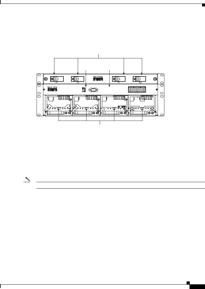
Figure 1-2 Component Locations (Front View) on the System Shelf with LCD Screen
Circuit Breaker Positions
10101
|
|
|
|
|
System |
GMT |
|
System |
Status |
Fuse |
|
LCD |
Controls |
Panel |
|
|
|
|
|
1RU Distribution Shelf
50A MAX
(F1-10)
15A MAX FUSE
System |
Shelf |
159330 |
Rectifier
Positions
Cisco AC/DC Power System User Guide, R1.0
1-2 |
May 2006 |
|
|
Chapter 1 Introduction
1.1.2 Rectifier Modules
Figure 1-3 shows a front view of the version of the system shelf that does not have an LCD screen. The optional 1 RU DC distribution shelf is also shown.
Figure 1-3 Component Locations (Front View) on the System Shelf without an LCD Screen
Circuit Breaker
Positions
System |
GMT Fuse |
Status |
Panel |
1RU Distribution
Shelf
50A MAX
(F1-10)
15A MAX FUSE
System Shelf
Rectifier
Positions
124778
1.1.2 Rectifier Modules
AC-to-DC power conversion is accomplished using two, three, or four hot-swappable CSCO-PWR-RECT rectifiers, each with an output voltage of nominal -48 VDC. Figure 1-4 shows a CSCO-PWR-RECT rectifier module.
Note The output voltage range is set at the factory and is not user configurable.
Cisco AC/DC Power System User Guide, R1.0
May 2006 |
1-3 |
Chapter 1 |
Introduction |
1.1.3 GMT Fuses
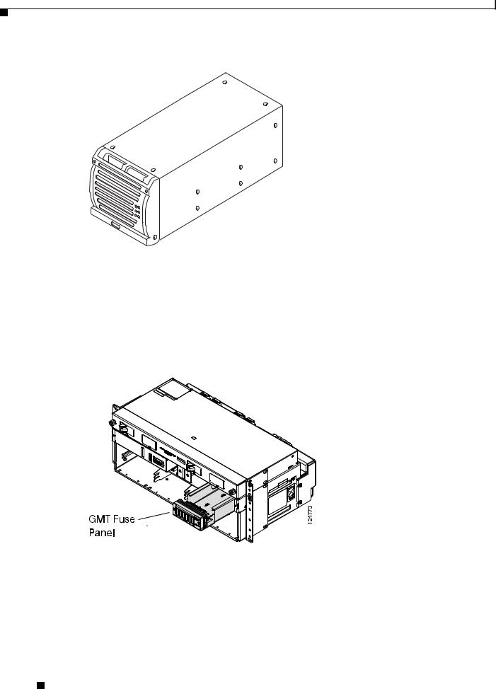
Figure 1-4 CSCO-PWR-RECT Rectifier Module
124776
1.1.3 GMT Fuses
The system shelf is equipped with a 10-position GMT fuse panel. The GMT fuse panel has a 50A maximum total capacity with a maximum fuse rating of up to 15A (for up to three positions). The fuses are alarmed and are reported through the system controller.
Figure 1-5 GMT Fuse Panel
1.1.4 1 RU Distribution Shelf
The optional 1RU Distribution Shelf is installed in systems that contain more than 2 rectifiers and acts as an additional protection point for system loads. The shelf has a rating of 96A and can be equipped with up to four circuit breakers (up to a maximum rating of 30A each). The breakers are alarmed through the system controller.
Cisco AC/DC Power System User Guide, R1.0
1-4 |
May 2006 |
|
|
Chapter 1 Introduction
1.1.5 System Configurations
Figure 1-6 1 RU Distribution Shelf
124761
The 1RU External Distribution Shelf can accommodate up to four Series-Trip circuit breaker positions. These breakers have “bullet type” connectors for quick connect and disconnect (Figure 1-7). Circuit breakers can be rated from 5A-30A.
Figure 1-7 Circuit Breaker
124767
1.1.5 System Configurations
Table 1-1 lists the configurations available for the Cisco AC/DC Power System.
Cisco AC/DC Power System User Guide, R1.0
|
May 2006 |
1-5 |
|
|
|

Chapter 1 |
Introduction |
1.1.6 General Specifications
Table 1-1 System Configurations
|
|
|
Output at |
Output at |
Configuration |
Rectifiers |
Distribution |
220V AC |
110V AC |
|
|
|
|
|
Small Systems |
2 CSCO-PWR-RECT Modules |
10-position GMT Fuse |
32A |
13.3A |
|
|
Block |
|
|
|
|
|
|
|
Medium Systems |
3 CSCO-PWR-RECT Modules |
10-position GMT Fuse |
64A |
26.6A |
|
|
Block |
|
|
|
|
4- position 1RU DC |
|
|
|
|
Distribution Shelf |
|
|
|
|
|
|
|
Large Systems |
4 CSCO-PWR-RECT Modules |
10-position GMT Fuse |
96A |
40A |
|
|
Block |
|
|
|
|
4- position 1RU DC |
|
|
|
|
Distribution Shelf |
|
|
|
|
|
|
|
1.1.6 General Specifications
Table 1-2 provides cabling specifications for the Cisco AC/DC Power System.
Table 1-2 Cabling Specifications
From |
To |
Wire Gauge |
Ampacity |
|
|
|
|
System Shelf |
1U DC Distribution |
4 x 6AWG (16mm²) |
96A (max) |
|
Shelf |
(intra-shelf cabling) |
|
|
|
|
|
|
|
|
|
Circuit Breakers |
Load |
10 - 8AWG |
30A (max) |
|
|
(6mm² - 10mm²) |
|
|
|
|
|
GMT Fuse Block |
Load |
16 - 14AWG |
15A (max) |
|
|
(1.5mm² - 2.5mm²) |
|
|
|
|
|
AC Service Panel |
System Shelf |
3 conductor 14AWG |
9.1A x (4) inputs |
|
|
(2.5mm²) per AC input |
<37A Total |
|
|
|
|
|
|
|
|
Table 1-3 provides electrical specifications for the Cisco AD/DC Power System.
Table 1-3 Electrical Specifications
Electrical |
Value |
|
|
Input Voltage |
(A) 100-120VAC |
|
(B) 200-250VAC |
|
|
Input Frequency |
44-66 Hz. |
|
|
Transient Response |
+/- 4%, recovery time 2ms |
|
|
Load Sharing |
+/- 5% of nominal current |
|
|
Table 1-4 provides protection specifications for the Cisco AC/DC Power System.
Cisco AC/DC Power System User Guide, R1.0
1-6 |
May 2006 |

Chapter 1 Introduction
1.1.6 General Specifications
Table 1-4 Protection Specifications
Protection |
Description |
|
|
Overcurrent (output) |
Short circuit and automatic current limiting |
|
|
Overvoltage |
Selective shutdown of modules at excessive |
|
output voltages |
|
|
Table 1-5 provides status and alarm specifications for the Cisco AC/DC Power System.
Table 1-5 Status and Alarm Specifications
Status & Alarms |
Description |
|
|
Alarm Contacts |
Four form-C alarm contacts (Low Voltage, Mains |
|
Error, Module Failure, Fuse/Circuit Breaker |
|
Failure), maximum 60 VDC, rated at 1A |
|
|
Status (Rectifier) |
Green LED indicates power is within acceptable |
|
range |
|
Yellow LED indicates current limit/thermal |
|
protection |
|
Red LED indicates overvoltage shutdown or |
|
rectifier alarm |
|
|
Table 1-6 provides mechanical specifications of the Cisco AC/DC Power System.
Table 1-6 Mechanical Specifications
Mechanical |
Description |
|
|
Shelf Dimensions |
17.4 x 5.25 x 10.8in. (442 x 132.9 x274mm) |
WxHxD |
|
|
|
1RU Shelf WxHxD |
17.1 x 1.69 x 9.175in. (434 x 43 x 233mm) |
|
|
Mounting |
ETSI, 19in. (IEC and ANSI) or 23in. |
|
|
Table 1-7 provides environmental specifications for the Cisco AC/DC Power System.
Table 1-7 Environmental Specifications
Environment |
Description |
|
|
Shock/Vibration |
(NEBS) Level 3, Class B Certification |
|
|
Earthquake |
Zone 4 Compliant |
|
|
Audible Noise |
<60 dBA |
|
|
Ambient Temperature |
-40°C to 55°C |
|
|
Storage Temperature |
-40°C to +85°C |
|
|
Relative Humidity |
10-90%, non-condensing |
|
|
Table 1-8 provides compliance specifications for the Cisco AC/DC Power System.
Cisco AC/DC Power System User Guide, R1.0
May 2006 |
1-7 |
Chapter 1 |
Introduction |
1.2 Safety Recommendations
Table 1-8 Compliance Specifications
Compliance |
Description |
|
|
Radiated EMC |
EN 61000-6-2, EN 61000-6-3, FCC Part 15 Class B |
|
|
EMC |
EN 61000-6-2, EN 61000-6-4 |
|
|
Safety |
CSA C22-2 No. 60950-1, UL 60950-1 and |
|
IEC60950-1/EN60950-1 |
|
|
ESD Immunity |
EN61000-4-2 |
|
|
RF Immunity |
EN61000-4-3 |
|
|
Surge Immunity |
IEC/EN61000-4-5 |
|
|
Fast Transient/Burst |
IEC/EN61000-4-4 |
Immunity |
|
|
|
Immunity |
EN61000-4-2 |
|
|
ETSI |
300-386-TC |
|
|
1
1.2 Safety Recommendations
Any device that uses electricity requires proper guidelines to ensure safety.
Warning Only trained and qualified personnel should be allowed to install, replace, or service this equipment.
Statement 1030
Warning This unit is intended for installation in restricted access areas. A restricted access area can be accessed only through the use of a special tool, lock and key, or other means of security.
Statement 1017
•The Cisco AC/DC Power System should only be installed or serviced by qualified personnel.
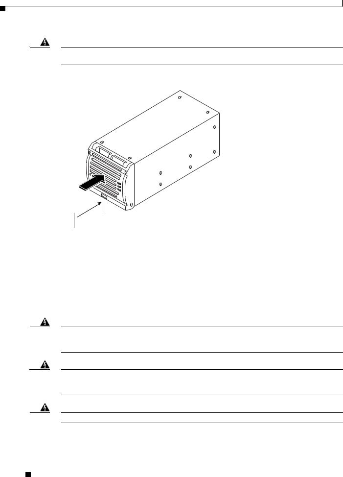
•An ESD wrist strap is included to protect sensitive electronics and should be connected to a metal surface to act as a ground. This ensures that all components have the same charge. An ESD wrist strap should be used when working with internal components that are installed in the shelf. The wrist strap connects at the rear of the system shelf as shown in Figure 1-8. If rear access is not available, the ESD wrist strap can be connected to the shelf mounting ears or the controller faceplate thumbscrews.
Cisco AC/DC Power System User Guide, R1.0
1-8 |
May 2006 |
Chapter 1 Introduction
1.2.1 Installation Warning
Figure 1-8 ESD Wrist Strap Connection Point
124769
ESD Connection
Point
•Keep the system area clear and dust-free during and after the installation.
•Always check for possible hazards before beginning work.
•This equipment is designed to permit the connection of a grounded conductor for the DC supply circuit at the equipment.
1.2.1Installation Warning
The following safety guidelines should be observed when transporting or moving the system to the install location:
•Before moving the Cisco AC/DC Power System, read the system specifications sheet to determine if the site meets all the size, environmental, and power requirements.
•The Cisco AC/DC Power System should be properly mounted to the equipment rack.
The Cisco AC/DC Power System is designed for installation in restricted access locations. A restricted access location is defined as an equipment location where both of the following conditions apply:
•Access can only be gained by service persons or users who understand the restrictions applied to the location and any precautions that must be taken.
•Access to the system is obtained through the use of a tool or lock and key, or other means of security, and is controlled by the authority responsible for the location.
1.2.2Operating Temperature Warnings
Warning To prevent the system from overheating, do not operate it in an area that exceeds the maximum recommended ambient temperature of: 55° Celsius.
Statement 1047
Cisco AC/DC Power System User Guide, R1.0
|
May 2006 |
1-9 |
|
|
|
Chapter 1 |
Introduction |
1.2.3 Electrical Safety Warnings
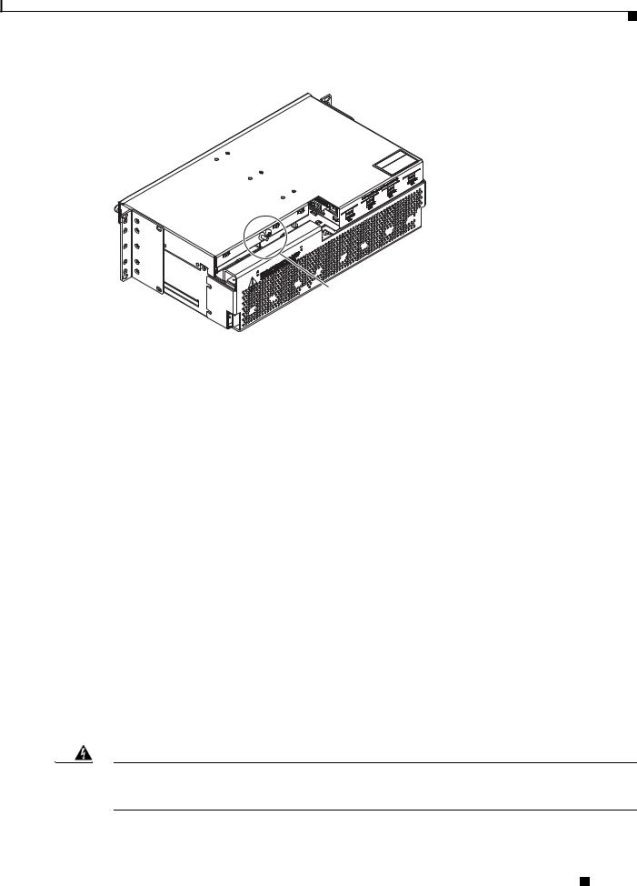
Warning To prevent airflow restriction, allow clearance around the ventilation openings to be at least 2.0 inches (50.8 mm).
Figure 1-9 Two-Inch Clearance Around Front Ventilation Opening
131187
Airflow
 2 in. 50.8 mm
This power system is intended for use in a restricted location where the ambient temperature falls between -40° and +55° Celsius. It is not recommended to continually operate the power system in an area that exceeds the maximum recommended operating temperature. To prevent the Cisco AC/DC Power System from overheating, the rectifier automatically shuts down when a thermal alarm is tripped.
1.2.3 Electrical Safety Warnings
The following are electrical safety recommendations for working near the Cisco AC/DC Power System:
Warning Before working on equipment that is connected to power lines, remove jewelry (including rings, necklaces, and watches). Metal objects will heat up when connected to power and ground and can cause serious burns or weld the metal object to the terminals. Statement 43
Warning This equipment must be grounded. Never defeat the ground conductor or operate the equipment in the absence of a suitably installed ground conductor. Contact the appropriate electrical inspection authority or an electrician if you are uncertain that suitable grounding is available. Statement 1024
Warning Installation of the equipment must comply with local and national electrical codes. Statement 1074
Cisco AC/DC Power System User Guide, R1.0
1-10 |
May 2006 |
|
|

Chapter 1 Introduction
1.2.3 Electrical Safety Warnings
Warning Before working on a chassis or working near power supplies, unplug the power cord on AC units; disconnect the power at the circuit breaker on DC units. Statement 12
Warning This product requires short-circuit (overcurrent) protection, to be provided as part of the building installation. Install only in accordance with national and local wiring regulations. Statement 1045
Warning Installation of the equipment must comply with local and national electrical codes. Statement 1074
•Before connecting the AC input source to the power system, always verify frequency and voltage.
•When making AC connections, all AC power and DC load distribution breakers should be in the OFF position.
•Ensure that the proper size circuit protection is being used.
Cisco AC/DC Power System User Guide, R1.0
May 2006 |
1-11 |

Chapter 1 |
Introduction |
1.2.3 Electrical Safety Warnings
Cisco AC/DC Power System User Guide, R1.0
1-12 |
May 2006 |
C H A P T E R 2
System Installation
This provides step-by-step instructions for installing a Cisco AC/DC Power System. If you are installing a new system, begin with the “2.1 Pre-Installation” section on page 2-1. If you are upgrading an existing system, go to the “2.6 System Upgrades” section on page 2-28 for instructions.
2.1 Pre-Installation
The following information should be reviewed before attempting to install the Cisco AC/DC Power System.This section includes shelf markings, tools, equipment, and an installation checklist. Refer to the “1.2 Safety Recommendations” section on page 1-8 before beginning installation.
Note Each system installation is unique, so please review specific site requirements and system configurations before installing the system.
2.1.1 Ground Symbol
Figure 2-1 shows the ground symbol located on the Cisco AC/DC Power System.
Figure 2-1 |
Ground Symbol |
124774
2.1.2 Tools Required
The following tools and parts are required for safe installation of the Cisco AC/DC Power System:
• Digital multimeter
Cisco AC/DC Power System User Guide, R1.0
|
May 2006 |
2-1 |
|
|
|
Loading...