


 Loading...
C H A P T E R 4
System Startup and Basic System
Configuration
The system startup process and a procedure for performing a basic configuration of your Cisco 12010, Cisco 12410, or Cisco 12810 router is presented in the following sections:
•Sources of Cisco IOS Software, page 4-2
•Preconfiguration Requirements, page 4-2
•Boot Process Overview, page 4-3
•Powering On the Router and Observing the Boot Process, page 4-4
•Manually Booting the System, page 4-11
•Configuring the Router, page 4-14
•Cisco IOS User Interface, page 4-15
•Configuring the Software Configuration Register, page 4-31
•Recovering a Lost Password, page 4-41
•Using RP Flash Memory Cards, page 4-44
•Post-Installation Procedures, page 4-63
|
|
Cisco 12010, Cisco 12410, and Cisco 12810 Router Installation and Configuration Guide |
|
|
|
|
|
||
|
OL-11496-01 |
|
|
4-1 |
|
|
|

Chapter 4 System Startup and Basic System Configuration
Sources of Cisco IOS Software
This chapter provides you with the information to configure your system so that it can access the network or enable other hosts in the network to access your system remotely by means of a Telnet connection. Detailed configuration procedures are beyond the scope of this document, but you can find more information in the “Post-Installation Procedures” section on page 4-63.
Sources of Cisco IOS Software
A default Cisco IOS software image for your system is available through any of the following internal or external sources:
•Onboard flash memory on the Route Processor (RP)—The latest Cisco IOS software image is preloaded into the flash memory, and it is a single inline memory module (SIMM). Flash memory is also referred to as nonvolatile random access memory (NVRAM). NVRAM retains its contents when you power off the system.
•Flash memory card—A flash memory card (sometimes referred to as a flash disk) inserted in a PCMCIA slot on the RP can serve as an external storage medium for a default Cisco IOS software image.
•TFTP server—A Trivial File Transfer Protocol (TFTP) server in the network can also function as an external source of a default Cisco IOS software image. You can download a valid Cisco IOS software image from such a remote host using a Telnet connection.
Preconfiguration Requirements
Before you configure your system, confirm the following:
•All cards are securely installed.
•All interface cable connections are secure and use cable strain relief where provided.
•All source power cables are securely fastened to the PDUs, and are connected to the appropriate power source.
|
Cisco 12010, Cisco 12410, and Cisco 12810 Router Installation and Configuration Guide |
4-2 |
OL-11496-01 |

Chapter 4 System Startup and Basic System Configuration
Boot Process Overview
•A terminal device is connected to the console port on the RP, powered on, and configured for 9600 bps, 8 data bits, no parity, and 2 stop bits (9600, 8N2).
Note You must connect a terminal to the RP to perform the initial configuration of the router.
•The flash memory card that shipped with your router is installed in slot 0 of the RP. The software configuration register is set to 0x0102 (default), causing the system to boot automatically from the Cisco IOS software image stored on the flash memory card.
After you complete the above, proceed to the following section to start the router.
Boot Process Overview
The following sequence summarizes a typical boot process.
1.You power on the router.
2.The RP MBus module receives +5 VDC voltage and starts executing MBus software.
3.The RP determines the router configuration by sending a message over the MBus requesting all installed devices to identify themselves. Their responses provide the RP with slot numbers, card, and component types.
4.The RP, line cards, switch fabric cards (CSCs and SFCs), and alarm card are then powered on.
5.The power-on-reset logic of the RP is delayed to allow power for both local and CSC clocks to stabilize.
6.After the power-on reset logic is released, the RP begins to execute the ROM monitor software.
–If the ROM monitor is configured to autoboot, the system automatically loads and boots the Cisco IOS software.
–If the ROM monitor is not configured to autoboot, you must boot the Cisco IOS software manually.
|
|
Cisco 12010, Cisco 12410, and Cisco 12810 Router Installation and Configuration Guide |
|
|
|
|
|
||
|
OL-11496-01 |
|
|
4-3 |
|
|
|

Chapter 4 System Startup and Basic System Configuration
Powering On the Router and Observing the Boot Process
7.When the Cisco IOS software boots, it polls all other cards in the system, powers them on, and loads the Cisco IOS software they require.
8.The RP waits for all other cards to finish their boot processes.
Powering On the Router and Observing the Boot
Process
The first time you start the router, observe the following conditions:
Step 1 Switch on all the circuit breakers that control power to the router.
Step 2 Observe the power entry module LEDs:
•AC PEMs—The green PWR OK LED should be on and the power supply fan operating.
•DC PEMs—The green PWR OK LED should be on and the power supply fan operating.
Step 3 Check the blower module:
•Ensure that the green OK LED is on.
•Listen for the blowers in the blower modules; you should hear them operating immediately. In a noisy environment, the blowers may be difficult to hear. You can place your hand in front of the exhaust vents near the top rear of the chassis to verify that the blower is operating.
|
Cisco 12010, Cisco 12410, and Cisco 12810 Router Installation and Configuration Guide |
4-4 |
OL-11496-01 |
Chapter 4 System Startup and Basic System Configuration
Powering On the Router and Observing the Boot Process
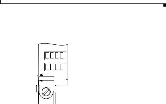
Step 4 Observe the RP alphanumeric LED displays during the RP boot process (Figure 4-1).
Figure 4-1 RP Alphanumeric LED Displays
PROCESSOR
 Upper alphanumeric
LED display (four digits)
 Lower alphanumeric
LED display (four digits)
H10780 |
Each 4-digit display shows part of a 2-line system message. During the RP boot process, the LED displays present a sequence of messages similar to that shown in Table 4-1.
Table 4-1 RP Alphanumeric LED Display Sequence Examples
|
LED Display1 |
Meaning |
Source |
||
|
MROM |
The MBus microcode begins to execute; nnnn is the microcode |
MBus |
||
|
nnnn |
version number. For example, microcode Version 1.17 appears as |
controller |
||
|
|
01172. |
|
|
|
|
LMEM |
Low memory on the RP is being tested. |
RP ROM |
||
|
TEST |
|
monitor |
||
|
|
|
|
||
|
MEM |
The size of main memory on the RP is being discovered. |
RP ROM |
||
|
INIT |
|
monitor |
||
|
|
|
|
||
|
RP |
The system is operational and ready to execute basic Cisco IOS |
RP ROM |
||
|
RDY |
software commands at the ROM monitor prompt (rommon>). |
monitor |
||
|
|
|
|
||
|
RP |
A valid Cisco IOS image is running. |
RP Cisco IOS |
||
|
UP |
|
software |
||
|
|
|
|
|
|
|
|
Cisco 12010, Cisco 12410, and Cisco 12810 Router Installation and Configuration Guide |
|
|
|
|
|
|
|||
|
OL-11496-01 |
|
|
|
4-5 |
|
|
|
|
||

Chapter 4 System Startup and Basic System Configuration
Powering On the Router and Observing the Boot Process
Table 4-1 RP Alphanumeric LED Display Sequence Examples (continued)
LED Display1 |
Meaning |
Source |
PRI |
The RP is enabled and is recognized as the system primary RP. A valid |
RP Cisco IOS |
RP |
Cisco IOS image is running. |
software |
|
|
|
SEC |
The RP is enabled and is recognized as the system secondary RP. A |
RP Cisco IOS |
RP |
valid Cisco IOS image is running. |
software |
|
|
|
1.Some LED sequences may occur too quickly to view.
2.The version of MBus microcode running on your system might be different.
Step 5 Observe the status of the RP interfaces (see Figure 4-2 for the GRP and Figure 4-3 for the PRP).
The LEDs on the RP show system status, the active flash memory card slot, the Ethernet connection in use, and the status of the Ethernet interface.
•PCMCIA flash memory card slot LEDs (labeled Slot-0 and Slot-1) are on when the slot is accessed.
•PRP—RJ-45 Ethernet port LEDs show the port activity:
–LINK: Link activity
–EN: port enabled
–TX: data transmission
–RX: data reception
•GRP—RJ-45 and MII Ethernet LEDs identify which of the two Ethernet connections is selected (only one port can be operational at a time). RJ-45 LEDs show port activity.
–LINK: Link activity
–COLL: Collision detection
–TX: data transmission
–RX: data reception
|
Cisco 12010, Cisco 12410, and Cisco 12810 Router Installation and Configuration Guide |
4-6 |
OL-11496-01 |

Chapter 4 System Startup and Basic System Configuration
Powering On the Router and Observing the Boot Process
Figure 4-2 GRP LEDs—Partial Front Panel View
EJECT |
|
SLOTSLOT |
|
- |
- |
0 |
1 |
AUX RESET |
|
LINK |
|
TX |
COLL |
|
RX |
MII
RJ - 45
H10762
Figure 4-3 PRP Ethernet Ports and LEDs—Partial Front Panel View
ETH 0
-1 SLOT0 - SLOT
PRIMARY
ETH 1
|
RX |
EN |
TX |
|
|
LINK |
PRIMARY |
|
|
RX |
EN |
TX |
|
|
LINK |
|
70693
|
|
Cisco 12010, Cisco 12410, and Cisco 12810 Router Installation and Configuration Guide |
|
|
|
|
|
||
|
OL-11496-01 |
|
|
4-7 |
|
|
|
Chapter 4 System Startup and Basic System Configuration
Powering On the Router and Observing the Boot Process
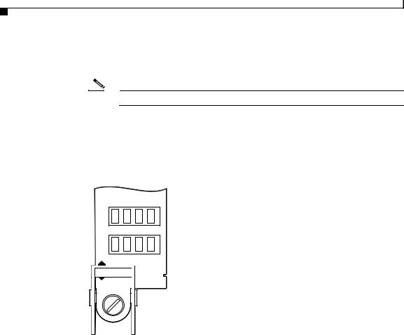
Step 6 During the line card boot process, observe the alphanumeric LED displays on each line card (Figure 4-4).
Note The line card boot process occurs immediately after the RP boot process.
The system attempts to boot identical line cards in parallel. Further, the system boots line cards as soon as they are powered on and become available. Each line card displays a sequence similar to those shown in Table 4-2.
Figure 4-4 Line Card Alphanumeric LED Displays—Partial View Shown
 Upper alphanumeric
LED display (four digits)
 Lower alphanumeric
LED display (four digits)
H11344 |
Table 4-2 Line Card Alphanumeric LED Display Sequence Examples
LED Display1 |
|
Meaning |
Source |
|||
MROM |
|
The MBus microcode begins to execute; nnnn is the microcode |
MBus |
|||
nnnn |
|
version number. For example, microcode Version 1.17 appears as |
controller |
|||
|
|
|
|
01172. |
|
|
LMEM |
|
Low memory on the line card is being tested. |
Line card |
|||
TEST |
|
|
ROM monitor |
|||
|
|
|
|
|||
MEM |
|
The size of main memory on the line card is being discovered. |
Line card |
|||
INIT |
|
|
ROM monitor |
|||
|
|
|
|
|
|
|
|
|
|
Cisco 12010, Cisco 12410, and Cisco 12810 Router Installation and Configuration Guide |
|
|
|
|
|
|
|
|
||
4-8 |
|
|
|
|
OL-11496-01 |
|
|
|
|
|
|
||

Chapter 4 System Startup and Basic System Configuration
Powering On the Router and Observing the Boot Process
Table 4-2 Line Card Alphanumeric LED Display Sequence Examples (continued)
LED Display1 |
Meaning |
Source |
ROMI |
The ROM image is being loaded into line card memory. |
RP Cisco IOS |
GET |
|
software |
|
|
|
FABL |
The line card is waiting for the fabric downloader to load.3 |
RP Cisco IOS |
WAIT |
|
software |
|
|
|
FABL |
The fabric downloader is being loaded into line card memory. |
RP Cisco IOS |
DNLD |
|
software |
|
|
|
FABL |
The fabric downloader is being launched. |
RP Cisco IOS |
STRT |
|
software |
|
|
|
FABL |
The fabric downloader is launched and running. |
RP Cisco IOS |
RUN |
|
software |
|
|
|
IOS |
Cisco IOS software is being downloaded into line card memory. |
RP Cisco IOS |
DNLD |
|
software |
|
|
|
IOS |
Cisco IOS software is being launched. |
RP Cisco IOS |
STRT |
|
software |
|
|
|
IOS |
Cisco IOS software is running. |
RP Cisco IOS |
UP |
|
software |
|
|
|
IOS |
The line card is enabled and ready for use. |
RP Cisco IOS |
RUN |
|
software |
|
|
|
1.Some LED sequences may occur too quickly to view. Sequence are shown in this tabular form as a baseline to represent line card functionality at startup.
2.The version of MBus microcode running on your system might be different.
3.The fabric downloader loads the Cisco IOS software image onto the line card.
|
|
Cisco 12010, Cisco 12410, and Cisco 12810 Router Installation and Configuration Guide |
|
|
|
|
|
||
|
OL-11496-01 |
|
|
4-9 |
|
|
|

Chapter 4 System Startup and Basic System Configuration
Powering On the Router and Observing the Boot Process
Step 7 The router automatically boots using the default image (if a flash memory card containing a valid Cisco IOS software image is inserted in slot 0 and the software configuration register is set to 0x0102).
As the router boots the Cisco IOS software image, a system banner similar to the following appears:
Cisco Internetwork Operating System Software
IOS (tm) GS Software (GSR-P-M), Experimental Version 12.0(20010120:204554) [gha]
Copyright (c) 1986-2001 by cisco Systems, Inc. Compiled Sat 20-Jan-01 18:34 by ghall
Note The system banner depends on the image version of the Cisco IOS software that the system is running. Your system banner might be different than the examples throughout this chapter.
•If the ROM monitor prompt (rommon>) displays, the router did not find a valid system image or the boot sequence was interrupted, and the system entered read-only memory (ROM) monitor mode.
In this case, you must boot a Cisco IOS software image manually by issuing the boot command.
–For information on locating a valid Cisco IOS software image, refer to the “Locating a Valid Cisco IOS Software Image” section on page 4-12.
–For information on using one of the various forms of the boot command, refer to the “Booting from the Cisco IOS Software Image” section on page 4-12.
•After manually booting the router, continue to Step 8.
Step 8 When you start an unconfigured system for the first time, the system automatically starts the system configuration dialog. The interactive script prompts you through the steps to create a router configuration file defining basic system operation parameters.
--- System Configuration Dialog ---
Continue with configuration dialog? [yes/no]:
The router uses the system configuration file to activate network connections to the RP so the router can be administered from a remote location, or to activate the line card network interfaces. After the initial configuration, the RP and line cards can communicate with external networks.
|
Cisco 12010, Cisco 12410, and Cisco 12810 Router Installation and Configuration Guide |
4-10 |
OL-11496-01 |
Chapter 4 System Startup and Basic System Configuration
Manually Booting the System
You do not need to configure the network interfaces immediately, but you cannot connect to a network until you configure the interfaces for operation in your network environment. For configuration information, see the “Configuring the Router” section on page 4-14.
Note The interface-specific LEDs on the line cards may not power on until you configure the line card interfaces. To verify correct operation of each line card interface, complete the first-time setup procedure and configuration, then check the status of the interfaces against the descriptions in the documentation for each line card.
If the system does not complete each of the preceding steps, go to the “Troubleshooting the Installation” chapter for troubleshooting recommendations and procedures.
Manually Booting the System
If your router does not find a valid system image, or if you interrupt the boot sequence, the system enters ROM monitor mode and displays the ROM monitor prompt (rommon>). From ROM monitor mode, you have access to commands which locate and boot a valid system image.
|
|
Cisco 12010, Cisco 12410, and Cisco 12810 Router Installation and Configuration Guide |
|
|
|
|
|
||
|
OL-11496-01 |
|
|
4-11 |
|
|
|

Chapter 4 System Startup and Basic System Configuration
Manually Booting the System
Locating a Valid Cisco IOS Software Image
Use the following procedure to locate a Cisco IOS software image to manually boot the router from the ROM monitor prompt (rommon>).
Step 1 Enter the ROM monitor mode dir bootflash command to examine the contents of the onboard flash memory in NVRAM on the RP.
rommon |
1> dir bootflash: |
|
|
File size |
Checksum |
File name |
|
3277967 bytes (0x32048f) |
0x6b331e30 |
gsr-p-mz.120-7.4.5 |
|
rommon |
2> |
|
|
•If the memory contains the desired Cisco IOS boot image, proceed to the “Booting from the Cisco IOS Software Image” section on page 4-12.
•If the onboard flash memory does not contain the desired Cisco IOS boot image, proceed to the next step.
Step 2 Enter the dir slotn: command, where n represents either slot 0 (0) or slot 1(1) to find a valid image by examining the contents of the flash memory card.
The following example shows the contents of the flash memory card in slot 0:
rommon |
2> dir slot0: |
|
|
File size |
Checksum |
File name |
|
3277967 bytes (0x32048f) |
0x6b331e30 |
gsr-p-mz.120-7.4.5 |
|
rommon |
3> |
|
|
After you locate a valid boot image, proceed to the “Booting from the Cisco IOS Software Image” section on page 4-12.
Booting from the Cisco IOS Software Image
To boot an image manually, issue the appropriate ROM monitor mode boot command after locating a valid Cisco IOS software image. Boot the image using one of the boot commands shown in Table 4-3.
|
Cisco 12010, Cisco 12410, and Cisco 12810 Router Installation and Configuration Guide |
4-12 |
OL-11496-01 |

Chapter 4 System Startup and Basic System Configuration
Manually Booting the System
Caution Use the boot flash command with care. Make sure that the flash memory card inserted in slot 0 contains a valid Cisco IOS software image; otherwise, you could instruct the system to boot an invalid image from the flash memory card. Before entering a boot command, always enter the dir slotn: command to examine the contents of a flash memory card.
Table 4-3 Boot Commands
Command |
Purpose |
|
|
boot |
(No argument.) Boots the default image in |
|
NVRAM. This image is loaded into memory |
|
at the factory. |
|
|
boot bootflash: filename |
Boots the router using the specified file in |
|
NVRAM. |
|
|
boot disk0: filename |
Boots the file filename from the flash disk in |
|
slot 0. |
|
|
boot disk1: filename |
Boots the file filename from the flash disk in |
|
slot 1. |
|
|
boot flash |
(Does not specify a particular PCMCIA slot.) |
|
Attempts to boot the router using the first file |
|
from the flash memory card in slot 0. |
|
|
boot slot0: filename |
Boots the specified file from the linear flash |
|
memory card in slot 0. |
|
|
boot slot1: filename |
Boots the specified file from the linear flash |
|
memory card in slot 1. |
|
|
boot tftp: filename [host] |
Boots the router using the specified file and |
or |
host name from a TFTP server in the network. |
|
|
boot [host] filename |
|
|
|
|
|
Cisco 12010, Cisco 12410, and Cisco 12810 Router Installation and Configuration Guide |
|
|
|
|
|
||
|
OL-11496-01 |
|
|
4-13 |
|
|
|

Chapter 4 System Startup and Basic System Configuration
Configuring the Router
Note If you did not change the configuration register setting, the next reload will revert to the default configuration register setting (0x0102). This setting causes the system to boot Cisco IOS software from a flash memory card inserted in slot 0 the next time you boot the router. See the “Configuring the Software Configuration Register” section on page 4-31 for additional information.
Configuring the Router
You can perform a basic configuration for your router by using one of the following methods:
•Method 1—Using the setup facility or the setup command.
During the initial startup of an unconfigured router, the system automatically runs the setup facility, which enables you to begin configuring your router manually. The setup facility presents a structured, interactive script that guides you through the process.
You can also invoke the setup facility at any time to alter previously entered configuration information by issuing the setup command at the privileged EXEC mode prompt (Milo#).
This method is described in the “Using Setup for Configuration Changes” section on page 4-18.
•Method 2—Using global configuration mode through the Cisco IOS command line user interface.
If you prefer not to use the interactive script of the setup facility to configure the router, you can configure it manually in global configuration mode. This method requires you to enter configuration commands on a line-by-line basis at the console without being prompted by a configuration script. This method is described in the “Using Global Configuration Mode” section on page 4-27.
|
Cisco 12010, Cisco 12410, and Cisco 12810 Router Installation and Configuration Guide |
4-14 |
OL-11496-01 |

Chapter 4 System Startup and Basic System Configuration
Cisco IOS User Interface
You can use the method that suits your operating style and your knowledge of network configuration requirements.
Whether you use the setup command facility or global configuration mode to configure the router to operate in your networking environment, be sure you know the:
•Interfaces the router has.
•Protocols the router is routing.
•Network addresses for the protocols being configured.
•Password scheme for your environment.
Cisco IOS User Interface
Cisco IOS software provides a command line interface that allows you to configure and manage your router. If you are not familiar with the Cisco IOS command line interface, you should read the “Using the Command Line Interface” chapter in the Configuration Fundamentals Configuration Guide. This section discusses the different command modes, context-sensitive help, and editing features of the interface.
Cisco IOS User Interface Command Modes
The Cisco IOS user interface is organized into several different modes. The available commands depend on which mode you are currently in. Entering a question mark (?) at the system prompt displays a list of commands available for the current command mode.
When you start a session on the router, you begin in user EXEC mode. Only a limited subset of the commands are available in EXEC mode. In order to have access to all of the commands, you must enter privileged EXEC mode which normally requires a password. From privileged EXEC mode, you can enter any EXEC command or enter global configuration mode. Most of the EXEC commands are 1-time commands, such as show commands, that show the current configuration status, and clear commands, that clear counters or interfaces. The EXEC commands are not saved across reboots of the router.
|
|
Cisco 12010, Cisco 12410, and Cisco 12810 Router Installation and Configuration Guide |
|
|
|
|
|
||
|
OL-11496-01 |
|
|
4-15 |
|
|
|

Chapter 4 System Startup and Basic System Configuration
Cisco IOS User Interface
The configuration modes allow you to make changes to the running configuration file. If you save the configuration, the commands are stored and persist across router reboots. In order to access the various configuration modes, you must start from global configuration mode. From global configuration mode, you can enter interface configuration mode, subinterface configuration mode, and a variety of protocol-specific modes.
ROM monitor mode, described earlier in this chapter, is a separate mode used when the router cannot boot properly. If your router does not find a valid system image when it is booting, or if its configuration file is corrupted at startup, the system typically enters ROM monitor mode.
User EXEC Mode
After the system boots successfully and loads the Cisco IOS software, the user EXEC mode prompt appears on the system console. The user EXEC mode prompt consists of the router host name followed by the right angle bracket (>). The following example shows the user EXEC mode prompt for a router with the factory default name Router.
Router>
Note The default host name is Router unless it was changed during initial configuration using the setup command facility.
Privileged EXEC Mode
To enter privileged EXEC mode, enter the enable command at the user EXEC mode prompt. If the enable secret password is set and saved in memory, the system prompts you to enter the enable secret password. The password does not appear on the window and is case sensitive. When the system accepts the password, the prompt changes to the privileged EXEC mode prompt, which consists of the router host name followed by the pound sign (#).
Note Because many of the privileged commands set operating parameters, privileged access should be password-protected to prevent unauthorized use.
|
Cisco 12010, Cisco 12410, and Cisco 12810 Router Installation and Configuration Guide |
4-16 |
OL-11496-01 |

Chapter 4 System Startup and Basic System Configuration
Cisco IOS User Interface
The following example shows the change from user EXEC mode to privileged EXEC mode.
Router> enable password: <password>
Router#
For information about using passwords, see the “Configuring Passwords” section on page 4-23.
Global Configuration Mode
Global configuration commands:
•Apply to features that affect the system as a whole, rather than just one protocol or interface.
•Use the configure terminal command to enter global configuration mode. From global configuration mode, you can access a number of other command modes.
•Enable particular routing or bridging functions.
For information on protocol-specific global configuration commands, refer to the appropriate configuration guide in the Cisco IOS software documentation.
Interface Configuration Mode
Use interface configuration commands to modify the operation of an interface such as Ethernet, FDDI, or a serial port. Interface configuration commands always follow an interface global configuration command, which defines the interface type.
For details on interface configuration commands that affect general interface parameters such as bandwidth and clock rate, refer to the “Interface Commands” chapter in the Configuration Fundamentals Command Reference. For protocol-specific commands, refer to the appropriate Cisco IOS software command reference guide.
|
|
Cisco 12010, Cisco 12410, and Cisco 12810 Router Installation and Configuration Guide |
|
|
|
|
|
||
|
OL-11496-01 |
|
|
4-17 |
|
|
|

Chapter 4 System Startup and Basic System Configuration
Cisco IOS User Interface
Subinterface Configuration Mode
Use subinterface configuration mode to configure multiple virtual interfaces (called subinterfaces) on a single physical interface. Subinterfaces appear to be distinct physical interfaces to the various protocols. For detailed information on how to configure subinterfaces, refer to the appropriate module for a specific protocol in the Cisco IOS software documentation.
ROM Monitor Mode
If the router cannot locate a valid system image, or if the boot sequence is interrupted, the system may enter ROM monitor mode. You can then boot the system manually or perform diagnostic tests.
You can also enter ROM monitor mode by entering the reload command from the privileged EXEC mode prompt and then pressing the Break key during the first 60 seconds of startup.
Using Setup for Configuration Changes
Use the setup command facility to perform first-time configuration and other basic configuration procedures on your router. This facility is based on a script that prompts you to enter basic configuration information to start a router quickly and uneventfully.
During the first-time startup of an unconfigured router, the system automatically starts the setup command facility and displays an interactive dialog called the system configuration dialog. The system configuration dialog guides you through the configuration process by prompting you for global (system-wide) parameters and interface (line card) parameters.
|
Cisco 12010, Cisco 12410, and Cisco 12810 Router Installation and Configuration Guide |
4-18 |
OL-11496-01 |

Chapter 4 System Startup and Basic System Configuration
Cisco IOS User Interface
To use the setup command to change a configuration:
1.You must toggle through each system configuration dialog prompt until you come to the item that you intend to change.
–To accept default settings for items that you do not want to change, press the Return key.
–To return to the privileged EXEC prompt without making changes and toggling through each system configuration dialog prompt, press Ctrl-C.
The setup command facility also provides help text for any prompt. To access help text, press the question mark (?) at a prompt.
2.When you complete your changes, the setup command facility displays the configuration command script that was created as a result of the changes you entered during the setup session. It also prompts you to use this configuration. There is no default for this prompt; you must answer either Yes or No.
•If you answer Yes, the configuration is saved to NVRAM.
•If you answer No, the configuration is not saved and the process begins again.
The following example shows typical output of a setup session automatically invoked during the initial startup of the router. The system banner appears, and then the system configuration dialog begins.
Note The output shown in this section are examples.Your configuration dialog might be different depending on which image of the Cisco IOS software you are using and how your router is equipped.
Cisco Internetwork Operating System Software
.
.
.
--- System Configuration Dialog ---
Continue with configuration dialog? [yes/no]: Yes
|
At any point you |
may enter a question mark '?' for help. |
||
|
Use ctrl-c to abort configuration dialog at any prompt. |
|||
|
Default settings |
are in square brackets '[]'. |
||
|
Basic setup only |
configures enough connectivity |
||
|
for management of the system, extended setup will ask you |
|||
|
Cisco 12010, Cisco 12410, and Cisco 12810 Router Installation and Configuration Guide |
|
|
|
|
||||
|
OL-11496-01 |
|
|
4-19 |
|
|
|
||

Chapter 4 System Startup and Basic System Configuration
Cisco IOS User Interface
to configure each interface of the system.
Would you like to enter basic management setup? [yes/no]: Yes Configuring global parameters:
Enter host name [Router]: Milo
The enable secret is a password used to protect access to privileged EXEC and configuration modes. This password, after entered, becomes encrypted in the configuration.
Enter enable secret [<Use current secret>]: barney
The enable password is used when you do not specify an
enable secret password, with some older software versions, and some boot images.
Enter enable password: wilma
The virtual terminal password is used to protect access to the router over a network interface. Enter virtual terminal password: bambam Configure SNMP Network Management? [no]:
Current interface summary |
|
|
|
|
Interface |
IP-Address |
OK? Method |
Status |
Protocol |
Ethernet0 |
unassigned |
YES unset |
administratively down down |
|
POS1/0 |
unassigned |
YES unset |
administratively down down |
|
SDCC1/0 |
unassigned |
YES unset |
administratively down down |
|
POS2/0 |
unassigned |
YES unset |
administratively down down |
|
SDCC1/0 |
unassigned |
YES unset |
administratively down down |
|
. |
|
|
|
|
. |
|
|
|
|
. |
|
|
|
|
POS15/0 |
unassigned |
YES unset |
administratively down down |
|
SDCC15/0 |
unassigned |
YES unset |
administratively down down |
|
Enter interface name used to connect to the
management network from the above interface summary: Ethernet0
Configuring interface Ethernet0:
Configure IP on this interface? Yes
IP address for this interface: 172.16.72.2
Subnet mask for this interface: 255.0.0.0
Class B network is 172.16.0.0, 8 subnet bits; mask is /24
The following configuration command script was created:
hostname Milo
enable secret 5 $1$krIg$emfYm/1OwHVspDuS8Gy0K1 enable password wilma
|
Cisco 12010, Cisco 12410, and Cisco 12810 Router Installation and Configuration Guide |
4-20 |
OL-11496-01 |
Loading...