


1040
Table of contents
 Loading...
Quick Start
Quick Start Guide for Cisco 1040 Sensor
1 Overview
2 Preparing to Connect Your Cisco 1040
3 Connecting Your Cisco 1040
4 Using Your Cisco 1040
5 Where to Go Next
6 Related Documentation
7 Technical Specifications
8 Regulatory Compliance and Safety Information for Your Cisco 1040
9 Obtaining Documentation
10 Documentation Feedback
11 Cisco Product Security Overview
12 Product Alerts and Field Notices
13 Obtaining Technical Assistance
14 Obtaining Additional Publications and Information

2
1 Overview
This guide is designed to help you quickly set up and use your Cisco 1040 Sensor (Cisco 1040). A
Cisco 1040 is a shelf-top unit that connects to the network and obtains Power over Ethernet (PoE)
through a Cisco Catalyst switch. It is easy to connect your Cisco 1040. These sections explain what a
Cisco 1040 does and how it fits in with products in the Cisco Unified Communications Management
Suite:
• Cisco 1040s and Cisco Unified Service Monitor, page 2
• Cisco 1040s and Cisco Unified Operations Manager, page 2
Cisco 1040s and Cisco Unified Service Monitor
Cisco 1040s listen to Real-Time Transport Protocol (RTP) voice traffic on a Switch Port Analyzer
(SPAN) port that you must configure to mirror voice traffic on phone ports or voice VLANs.
Cisco 1040 calculates Mean Opinion Scores (MOS) and sends data at 60-second intervals to Cisco
Unified Service Monitor (Service Monitor), a product from the Cisco Unified Communications
Management Suite.
Service Monitor examines the MOS value and compares it against a user-specified threshold value for
the codec in use on the call. When MOS drops below the threshold, Service Monitor generates SNMP
traps and sends them to up to four recipients. A single Service Monitor can receive and analyze MOS
data from multiple Cisco 1040s. If you have more than one Service Monitor, you can configure
Cisco 1040s to fail over to a secondary service monitor. For more information, see User Guide for
Cisco Unified Service Monitor.
Cisco 1040s and Cisco Unified Operations Manager
You can use Cisco Unified Operations Manager (Operations Manager) to further analyze, display, and
act on the traps that Cisco 1040 generates. When configured as a trap recipient from Service Monitor,
Operations Manager generates service quality events, displays and tracks these events on a real-time
dashboard, and displays and stores event history. You can configure additional event settings on
Operations Manager that alert you to low MOS and to the occurrence of many service quality events
during a period of time. In addition, you can configure Operations Manager to send notifications by
e-mail, SNMP trap, and syslog message.

3
2 Preparing to Connect Your Cisco 1040
This section describes tasks that you must perform the first time you set up your network to support
Cisco 1040 operations. If you have not already completed the following tasks, it is advisable to
complete them so that your Cisco 1040 becomes fully operational minutes after you connect it.
Install and Configure Cisco Unified Service Monitor
Instructions for completing these tasks are available in User Guide for Cisco Unified Service Monitor
and in Service Monitor online help. Using Service Monitor, perform the following tasks:
• Set up Service Monitor. Among other parameters, you will specify a TFTP server.
• Edit configuration files for Cisco 1040s.
Configure DHCP Server Option 150
Configure your DHCP server so that option 150 returns the IP address for the TFTP server and
provides an IP address, subnet mask, default gateway, and, optionally, a DNS server for a Cisco 1040.
If you would like to configure a Cisco router as a DHCP server, see the following URL.
http://www.cisco.com/en/US/tech/tk648/tk361/technologies_tech_note09186a0080114aee.shtml
(Optional) Configure DNS
If you are using DNS in your network, configure DNS entries for Cisco 1040s.
3 Connecting Your Cisco 1040
Note Be sure to read the “Regulatory Compliance and Safety Information for Your Cisco 1040”
section on page 13 before connecting your Cisco 1040.
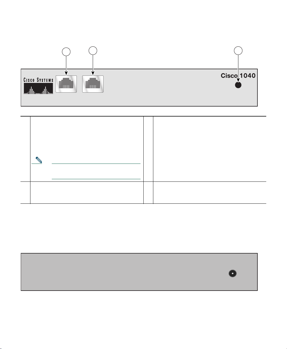
Figure 1 shows the connections and indicators on the front panel of your Cisco 1040.
4
Figure 1 Cisco 1040 Cable Connections—Front Panel
Figure 2 shows the connection on the rear panel of your Cisco 1040 for an external, separately
certified AC/DC power supply, for use if IEEE 802.3af-compliant PoE is not available. See Cable
Specifications, page 12.
Figure 2 Cisco 1040 Cable Connections—Rear Panel
1
10/100-1—Fast Ethernet port, standard RJ45
for connecting to the network and obtaining
inline power.
This port supports IEEE 802.3af standard
PoE.
Note This port does not support Cisco
prestandard PoE.
3
Status indicator light—See Understanding the
Status Indicator Light, page 7.
2
10/100-2—Fast Ethernet port, standard RJ45
for connecting to a SPAN or Remote SPAN
(RSPAN) destination port.
—
—
10/100-1 10/100-2
POWER
141283
1
2 3
POWER
DC 5V 2.5A
141284

5
Cisco 1040 Port Usage
This section provides a list of ports used by the Cisco 1040, for your reference.
Selecting and Configuring a Cisco Catalyst Switch
To connect the Cisco 1040, you need a Cisco Catalyst switch with the following:
• A port that supports IEEE 802.3af standard Power over Ethernet (PoE).
• A port that is configured as a SPAN or RSPAN destination port for:
–
Ports to which phones are connected
–
VLANs
For information about configuring SPAN and RSPAN on Cisco Catalyst switches and modules,
see the following URL.
http://www.cisco.com/en/US/products/hw/switches/ps708/products_tech_note09186a008015c612.
shtml
Connecting the Cisco 1040 to the Cisco Catalyst Switch
Before you begin this procedure, see the regulatory compliance and safety information Statement
1001—Work During Lightning Activity, page 23.
Table 1 Cisco 1040 Port Usage
Protocol Port Number Service Name
UDP 53 DNS
UDP 67 and 68 DHCP
UDP 69 TFTP—Cisco 1040 uses TFTP to get a configuration file and
binary image file.
UDP 5666 Syslog—Cisco 1040 sends syslog messages to Service Monitor.
TCP 2000 SCCP—Cisco 1040 uses SCCP to communicate with Service
Monitor.
TCP 80 http—Cisco 1040 has a web-based user interface to view its
configuration

6
Step 1 Place the Cisco 1040 on top of the appropriate Cisco Catalyst switch.
Note The minimum height necessary to install the Cisco 1040 is 5.08 cm (2 in.). The
installation of the unit should not restrict the airflow around the device. When
operating the unit, ensure that no objects are placed on top of the unit.
Step 2 Connect a Category 5 straight-through cable from 10/100-1 (Fast Ethernet port 1) on the
Cisco 1040 to a port that supports IEEE 802.3af standard PoE on the Cisco Catalyst switch.
Step 3 Connect a Category 5 straight-through cable from 10/100-2 (Fast Ethernet port 2) on the
Cisco 1040 to a port that you have configured as a SPAN (or RSPAN) destination port on the
Cisco Catalyst switch.
Note Verify that this port on the switch is set up to mirror a VLAN or switch ports to which
phones are connected.
A startup process begins on the Cisco 1040. The status indicator on the front of the Cisco 1040
should flash amber, turn yellow, and then turn green. For more information, see Understanding
the Status Indicator Light, page 7.
4 Using Your Cisco 1040
After you have successfully connected your Cisco 1040, use Service Monitor to manage and configure
it. For example, you will use Service Monitor to specify the TFTP server to use, update configuration
files, set the time, and reset Cisco 1040s.
This section describes information that you can obtain directly from a Cisco 1040:
• Understanding the Status Indicator Light, page 7
• Using the Cisco 1040 Web Interface, page 8
Note Information obtained directly from a Cisco 1040 is also available in another form from
Service Monitor. Service Monitor displays the status of Cisco 1040s.

7
Understanding the Status Indicator Light
The status indicator light on the front panel of a Cisco 1040 indicates what the Cisco 1040 is currently
doing. The following table lists the conditions that the status indicator light can be in and places the
conditions in startup sequence order.
Startup
Sequence
Number Status Indicator Light Cisco 1040 Condition
1 Orange solid Initial state
2 Yellow and flashing Obtained power from the switch and is doing one of the
following:
1. Obtaining an IP address using DHCP.
2. Accessing the TFTP server.
3. Requesting the configuration file and the binary
image file.
3 Yellow solid Registering to a service monitor.
Note If unable to register, the Cisco 1040 returns to
startup sequence number 2.
4 Green solid or green and
flashing
Registered to a service monitor:
• Green solid—Registered to the primary service
monitor.
• Green and flashing—Registered to a secondary
service monitor. When the primary service monitor
is available again, Cisco 1040 registers with it again
and the status indicator light turns green solid.

8
Using the Cisco 1040 Web Interface
You can open a web interface to view information stored on a Cisco 1040 as follows.
Step 1 In your browser, enter http://<IP address or DNS name> where IP address is the address of
your Cisco 1040 and DNS name is the DNS name for the Cisco 1040. For example:
http://Cisco-1040-sj
The Device Information window displays the following information:
• ID—Cisco 1040 ID.
• MAC Address—Cisco 1040 MAC address.
• Time stamp—Current time on the Cisco 1040.
• Status—Status of the Cisco 1040; one of the following:
–
operational—Cisco 1040 is receiving RTP streams, analyzing the data, and sending
syslog messages when required.
–
not communicating with receiver—The Service Monitor is unreachable.
• Current Service Monitor—IP address or DNS name of the service monitor to which the
Cisco 1040 is registered; this could be the primary or secondary service monitor.
• TFTP IP Address—IP address of the TFTP server from which the Cisco 1040 obtains a
configuration file and binary image file.
• Switch IP Address—Switch that this Cisco 1040 is connected to.
• Switch Port—Switch port that this Cisco 1040 is connected to.
• Software Version—Name of the binary image file installed on the Cisco 1040.
• Last Updated—The last time that the configuration for the Cisco 1040 was updated.
Step 2 To view the contents of the configuration file on the TFTP server for this Cisco 1040, enter
http://<IP address or DNS name>/Communication where IP address is the address of your
Cisco 1040 and DNS name is the DNS name for the Cisco 1040. For example:
http://Cisco-1040-sj/Communication
The Communication Log File window displays the following information, which is stored in
the configuration file on the TFTP server:
• Receiver—IP address or DNS name of each Service Monitor defined in the configuration
file—primary or secondary—separated by semicolons.
• ID—ID of the Cisco 1040 that uses this configuration file.
• Image—Name of the binary image file that the Cisco 1040 should download and run
from the TFTP server.

9
• Last Updated—The last time that this configuration file was updated on the Service
Monitor system.
• CDPGlobalRunState—States whether CDP is enabled (true) or disabled (false).
• SyslogPort—States the port protocol (UDP) and port number used for sending syslogs to
Service Monitor.
• SkinnyPort—States the port protocol (TCP) and port number used to communicate with
Service Monitor.
5 Where to Go Next
After you have performed first time installation tasks and connected a Cisco 1040, Cisco 1040 starts
listening to RTP traffic and sending MOS data to Service Monitor. For more information, see the
following User Guides for Cisco Unified Communications Management Suite applications:
• User Guide for Cisco Unified Service Monitor
• User Guide for Cisco Unified Operations Manager
You can access these documents:
• In PDF in the Documentation directory on the respective product CD-ROM.
• In HTML and PDF on Cisco.com.
From Cisco.com:
a. Enter the URL,
http://www.cisco.com/univercd/cc/td/doc/product/rtrmgmt/cw2000/index.htm
b. Select the appropriate application.
c. Select appropriate application version.
d. Select User Guide.
• From the CiscoWorks Online help:
a. From the CiscoWorks Homepage, click Help.
b. Select the appropriate Cisco Unified Communications Management Suite application.

10
6 Related Documentation
Note Although every effort has been made to validate the accuracy of the information in the printed
and electronic documentation, updates are sometimes necessary. Any changes to the original
publications are reflected on Cisco.com, where you will find the most up-to-date
documentation.
For information about configuring SPAN and RSPAN ports on Cisco Catalyst switches, see the
software configuration guide for the appropriate switch model and Cisco IOS version. Use this
procedure to locate software configuration guides for Cisco Catalyst switches.
Step 1 Log into Cisco.com at http://www.cisco.com.
Step 2 Select Technical Support & Documentation > Documentation.
Step 3 Select Switches.
Step 4 Select the appropriate model Cisco Catalyst switch.
Step 5 Select Configuration Guides.
Step 6 Select the software configuration guide for the Cisco Catalyst switch model and Cisco IOS
version that is running on the switch.
For information about installing, troubleshooting, and using the applications related to Cisco 1040
see Table 2.
Note To view documents in Adobe Portable Document Format (PDF), Adobe Acrobat 4.0 or later
is required. To view documents on Cisco.com, log on to your Cisco.com home page, then enter
the URL, http://www.cisco.com/univercd/cc/td/doc/product/rtrmgmt/cw2000/index.htm.

11
7 Technical Specifications
These sections describe the technical specifications for Cisco 1040:
• Physical and Operating Environment Specifications, page 12
• Cable Specifications, page 12
• Network Port Pinouts, page 12
Table 2 Related Documentation
To learn
more about... See this document
In the
product
package?
On the
product
CD?
On
Cisco.com?
On the
Cisco
Doc.
DVD?
In the
online
help?
The known
product bugs
(DDTS)
Release Notes for Cisco
Unified Service Monitor
No Yes Yes Yes No
Release Notes for Cisco
Unified Operations
Manager
No No
Performing a
typical or custom
installation
Quick Start Guide for
Cisco Unified Service
Monitor
No Yes Yes Yes No
Installation Guide for
Cisco Unified Operations
Manager (Includes Service
Monitor)
No No Yes Yes No
Features, tasks,
and
troubleshooting
User Guide for Cisco
Unified Service Monitor
No Yes Yes Ye s Yes
1
1. From the Service Monitor Homepage, click Help.
User Guide for Cisco
Unified Operations
Manager
No No Yes Yes No

12
Physical and Operating Environment Specifications
Cable Specifications
• RJ-45 jack for the LAN 10/100BaseT connection (10/100-1)
• RJ-45 jack for the second LAN 10/100BaseT compliant connection (10/100-2)
Caution External AC/DC Power Supply Specification: You must use a separately certified
AC-to-DC Power Supply. This Power Supply must be rated: 5vDC 2.5A certified and
marked: Limited Power Source (or L.P.S.).
Network Port Pinouts
Specification Value or Range
Operating temperature 0° to 40°C (32° to 104°F)
Operating relative humidity 10% to 90% (non-condensing)
Height 3.8 cm (1.5 in.)
Width 24.1 cm (9.5 in.)
Depth 20.3 cm (8 in.)
Weight .5kg (1.0 lb.)
Power 2.5A, 5vDC
Cables Two (2) Category 5 cables
Pin Number Function
1 DSR/RI—Data set ready/ring indicator
2 DCD—Data carrier detect
3 DTR—Data terminal ready
4 SGND—Signal Ground
5 RD—Receive Data
6 TD—Transmit Data

13
8 Regulatory Compliance and Safety Information for Your
Cisco 1040
Caution If the Cisco 1040 is used in a manner not specified by Cisco, the protection provided in
the equipment might be impaired.
Caution Inline power circuits provide current through the communication cable. Use the
Cisco-provided cable or a minimum 24 AWG communication cable (for example, CAT 5,
24 AWG).
Caution The Cisco 1040 has no operator-serviceable parts inside.
Regulatory compliance and safety information for Cisco 1040 includes the following sections:
• Warning Definition—Statement 1071, page 14
• Translated Warnings, page 21
• European Directives, page 40
• Regulatory Standards Compliance, page 42
• EMC Environmental Conditions for Products Installed in the European Union, page 43
• EMC Class B Notices and Warnings, page 43
7 CTS—Clear to send
8 RTS—Request to send
Pin Number Function

14
Warning Definition—Statement 1071
Warning
IMPORTANT SAFETY INSTRUCTIONS
This warning symbol means danger. You are in a situation that could cause
bodily injury. Before you work on any equipment, be aware of the hazards
involved with electrical circuitry and be familiar with standard practices for
preventing accidents. Use the statement number provided at the end of each
warning to locate its translation in the translated safety warnings that
accompanied this device.
Statement 1071
SAVE THESE INSTRUCTIONS
Waarschuwing
BELANGRIJKE VEILIGHEIDSINSTRUCTIES
Dit waarschuwingssymbool betekent gevaar. U verkeert in een situatie die
lichamelijk letsel kan veroorzaken. Voordat u aan enige apparatuur gaat
werken, dient u zich bewust te zijn van de bij elektrische schakelingen
betrokken risico's en dient u op de hoogte te zijn van de standaard praktijken
om ongelukken te voorkomen. Gebruik het nummer van de verklaring
onderaan de waarschuwing als u een vertaling van de waarschuwing die bij
het apparaat wordt geleverd, wilt raadplegen.
BEWAAR DEZE INSTRUCTIES
Varoitus
TÄRKEITÄ TURVALLISUUSOHJEITA
Tämä varoitusmerkki merkitsee vaaraa. Tilanne voi aiheuttaa ruumiillisia
vammoja. Ennen kuin käsittelet laitteistoa, huomioi sähköpiirien
käsittelemiseen liittyvät riskit ja tutustu onnettomuuksien yleisiin
ehkäisytapoihin. Turvallisuusvaroitusten käännökset löytyvät laitteen
mukana toimitettujen käännettyjen turvallisuusvaroitusten joukosta
varoitusten lopussa näkyvien lausuntonumeroiden avulla.
SÄILYTÄ NÄMÄ OHJEET

15
Attention
IMPORTANTES INFORMATIONS DE SÉCURITÉ
Ce symbole d'avertissement indique un danger. Vous vous trouvez dans une
situation pouvant entraîner des blessures ou des dommages corporels. Avant
de travailler sur un équipement, soyez conscient des dangers liés aux circuits
électriques et familiarisez-vous avec les procédures couramment utilisées
pour éviter les accidents. Pour prendre connaissance des traductions des
avertissements figurant dans les consignes de sécurité traduites qui
accompagnent cet appareil, référez-vous au numéro de l'instruction situé à la
fin de chaque avertissement.
CONSERVEZ CES INFORMATIONS
Warnung
WICHTIGE SICHERHEITSHINWEISE
Dieses Warnsymbol bedeutet Gefahr. Sie befinden sich in einer Situation, die
zu Verletzungen führen kann. Machen Sie sich vor der Arbeit mit Geräten mit
den Gefahren elektrischer Schaltungen und den üblichen Verfahren zur
Vorbeugung vor Unfällen vertraut. Suchen Sie mit der am Ende jeder Warnung
angegebenen Anweisungsnummer nach der jeweiligen Übersetzung in den
übersetzten Sicherheitshinweisen, die zusammen mit diesem Gerät
ausgeliefert wurden.
BEWAHREN SIE DIESE HINWEISE GUT AUF.
Avvertenza
IMPORTANTI ISTRUZIONI SULLA SICUREZZA
Questo simbolo di avvertenza indica un pericolo. La situazione potrebbe
causare infortuni alle persone. Prima di intervenire su qualsiasi
apparecchiatura, occorre essere al corrente dei pericoli relativi ai circuiti
elettrici e conoscere le procedure standard per la prevenzione di incidenti.
Utilizzare il numero di istruzione presente alla fine di ciascuna avvertenza per
individuare le traduzioni delle avvertenze riportate in questo documento.
CONSERVARE QUESTE ISTRUZIONI

16
Advarsel
VIKTIGE SIKKERHETSINSTRUKSJONER
Dette advarselssymbolet betyr fare. Du er i en situasjon som kan føre til skade
på person. Før du begynner å arbeide med noe av utstyret, må du være
oppmerksom på farene forbundet med elektriske kretser, og kjenne til
standardprosedyrer for å forhindre ulykker. Bruk nummeret i slutten av hver
advarsel for å finne oversettelsen i de oversatte sikkerhetsadvarslene som
fulgte med denne enheten.
TA VARE PÅ DISSE INSTRUKSJONENE
Aviso
INSTRUÇÕES IMPORTANTES DE SEGURANÇA
Este símbolo de aviso significa perigo. Você está em uma situação que poderá
ser causadora de lesões corporais. Antes de iniciar a utilização de qualquer
equipamento, tenha conhecimento dos perigos envolvidos no manuseio de
circuitos elétricos e familiarize-se com as práticas habituais de prevenção de
acidentes. Utilize o número da instrução fornecido ao final de cada aviso para
localizar sua tradução nos avisos de segurança traduzidos que acompanham
este dispositivo.
GUARDE ESTAS INSTRUÇÕES
¡Advertencia!
INSTRUCCIONES IMPORTANTES DE SEGURIDAD
Este símbolo de aviso indica peligro. Existe riesgo para su integridad física.
Antes de manipular cualquier equipo, considere los riesgos de la corriente
eléctrica y familiarícese con los procedimientos estándar de prevención de
accidentes. Al final de cada advertencia encontrará el número que le ayudará
a encontrar el texto traducido en el apartado de traducciones que acompaña
a este dispositivo.
GUARDE ESTAS INSTRUCCIONES
Loading...