


Owner’s Manual & Safety Instructions
Save This Manual Keep this manual for the safety warnings and precautions, assembly, operating, inspection, maintenance and cleaning procedures. Write the product’s serial number in the back of the manual near the assembly diagram (or month and year of purchase if product has no number). Keep this manual and the receipt in a safe and dry place for future reference.
Visit our website at: http://www.harborfreight.com
Email our technical support at: tech@harborfreight.com
When unpacking, make sure that the product is intact and undamaged. If any parts are missing or broken, please call 1-800-444-3353 as soon as possible.
Copyright© 2011 by Harbor Freight Tools®. All rights reserved. No portion of this manual or any artwork contained herein may be reproduced in any shape or form without the express written consent of Harbor Freight Tools. Diagrams within this manual may not be drawn proportionally. Due to continuing improvements, actual product may differ slightly from the product described herein. Tools required for assembly and service may not be included.
Read this material before using this product. Failure to do so can result in serious injury. SAVE THIS MANUAL.
SAFETY
SETUP
WELDING BASIC
TIPS WELDING
MAINTENANCE
Table of Contents
Safety.......................................................... |
2 |
Welding Tips............................................... |
23 |
Setup........................................................... |
7 |
Maintenance............................................... |
27 |
Specifications.............................................. |
7 |
Parts List and Diagrams............................. |
30 |
Basic Welding............................................ |
15 |
Warranty..................................................... |
32 |
WARNING SYMBOLS AND DEFINITIONS
This is the safety alert symbol. It is used to alert you to potential personal injury hazards. Obey all safety messages that follow this symbol to avoid possible injury or death.
Indicates a hazardous situation which, if not avoided, will result in death or serious injury.
Indicates a hazardous situation which, if not avoided, could result in death or serious injury.
Indicates a hazardous situation which, if not avoided, could result in minor or moderate injury.
Addresses practices not related to personal injury.
IMPORTANT SAFETY INFORMATION
Read all safety warnings and instructions.
Failure to follow the warnings and instructions may result in electric shock, fire and/or serious injury.
Save all warnings and instructions for future reference.
General Safety
PROTECT yourself and others. Read and understand this information.
1.Before use, read and understand manufacturer′s instructions, Material Safety Data Sheets (MSDS′s),
employer′s safety practices, and ANSI Z49.1.
2.Keep out of reach of children.
Keep children and bystanders away while operating.
3.Place the welder on a stable location before use.
If it falls while plugged in, severe injury, electric shock, or fire may result.
4.Do not overreach.
Keep proper footing and balance at all times.
5.Stay alert, watch what you are doing and use common sense when operating a welder.
Do not use a welder while you are tired or under the influence of drugs, alcohol or medication.
A moment of inattention while operating welders may result in serious personal injury.
6.Avoid unintentional starting. Make sure you are prepared to begin work before turning on the Welder.
7.Never leave the Welder unattended while energized. Turn power off if you have to leave.
8.The warnings, precautions, and instructions discussed in this instruction manual cannot cover all possible conditions and situations that may occur. It must be understood by the operator that common sense and caution are factors which cannot be built into this product, but must be supplied by the operator.
9.This product, when used for welding and similar applications, contains or produces a chemical known to the State of California to cause cancer and birth defects (or other reproductive harm).
(California Health & Safety Code § 25249.5, et seq.)
10.Handling the cord on this product will expose you to lead, a chemical known to the State of California to cause cancer, and birth defects or other reproductive harm.
Wash hands after handling.
(California Health & Safety Code § 25249.5, et seq.)
Page 2 |
For technical questions, please call 1-800-444-3353. |
SKU 68886 |

Fume and Gas Safety
FUMES AND GASES can be hazardous to your health.
1.Exposure to welding or cutting exhaust fumes can increase the risk of developing certain cancers, such as cancer of the larynx and lung cancer.
Also, some diseases that may be linked to exposure to welding or cutting exhaust fumes are:
• Early onset of Parkinson’s Disease
• Heart disease |
• Ulcers |
4.Use enough ventilation, exhaust at arc, or both, to keep fumes and gases from breathing zone and general area. If engineering controls are not feasible, use an approved respirator.
5.Work in a confined area only if it is well-ventilated, or while wearing an air-supplied respirator.
•Damage to the reproductive organs
•Inflammation of the small intestine or
stomach |
• Kidney damage |
• Respiratory diseases such as emphysema, bronchitis, or pneumonia
2.Do not use near degreasing or painting operations.
3.Keep head out of fumes.
Do not breathe exhaust fumes.
6.Have a recognized specialist in
Industrial Hygiene or Environmental Services check the operation and air quality
and make recommendations
for the specific welding situation.
Follow OSHA guidelines for
Permissible Exposure Limits (PEL’s) and the American Conference of Governmental Industrial Hygienists recommendations for
Threshold Limit Values (TLV’s) for fumes and gases.
Arc Ray Safety
ARC RAYS can injure eyes and burn skin.
1.Wear ANSI-approved welding eye protection featuring at least a number 10 shade lens rating.
2.Wear leather leggings, fire resistant shoes or boots during use. Do not wear pants with cuffs, shirts with open pockets, or any clothing that can catch and hold molten metal or sparks.
3.Keep clothing free of grease, oil, solvents, or any flammable substances.
Wear dry, insulating gloves and protective clothing.
4.Wear an approved head covering to protect the head and neck. Use aprons, cape, sleeves, shoulder covers, and bibs designed and approved for welding and cutting procedures.
5.When welding/cutting overhead or in confined spaces, wear flame resistant ear plugs or
ear muffs to keep sparks out of ears.
SAFETY
SETUP
BASIC WELDING
WELDING TIPS
MAINTENANCE
SKU 68886 |
For technical questions, please call 1-800-444-3353. |
Page 3 |

SAFETY
SETUP
Electrical Safety
ELECTRIC SHOCK can KILL.
1.Turn off, disconnect power, and
discharge electrode to ground before setting down torch/electrode holder and before service.
2.Do not touch energized electrical parts.
Wear dry, insulating gloves. Do not touch electrode holder, electrode, welding torch, or welding wire with bare hand. Do not wear wet or damaged gloves.
3.Connect to grounded, GFCI protected power supply only.
4.Do not use near water or damp objects.
5.People with pacemakers should consult their physician(s) before use. Electromagnetic fields in close proximity to heart pacemaker could cause pacemaker interference or pacemaker failure.
6.Do not expose welders to rain or wet conditions.
Water entering a welder will increase the risk of electric shock.
7.Do not abuse the cord. Never use the cord for carrying, pulling or unplugging the welder. Keep cord away from heat, oil, sharp edges or moving parts. Damaged or entangled
cords increase the risk of electric shock.
8.Do not use outdoors.
9.Insulate yourself from the workpiece and ground.
Use nonflammable, dry insulating material if possible, or use dry rubber mats, dry wood or plywood, or other dry insulating material large enough to cover your full area of contact with the work or ground.
WELDING BASIC
TIPS WELDING
MAINTENANCE
Fire Safety
ARC AND HOT SLAG can cause fire.
1.Clear away or protect flammable objects.
Remove or make safe all combustible materials for a radius of 35 feet (10 meters) around the work area. Use a fire resistant material to cover or block all open doorways, windows, cracks, and other openings.
2.Keep ABC-type fire extinguisher near work area and know how to use it.
3.Maintain a safe working environment.
Keep the work area well lit.
Make sure there is adequate surrounding workspace. Keep the work area free of obstructions,
grease, oil, trash, and other debris.
4.Do not operate welders in atmospheres containing dangerously reactive or flammable liquids, gases, vapors, or dust.
Provide adequate ventilation in work areas to prevent accumulation of such substances.
Welders create sparks which may ignite flammable substances or make reactive fumes toxic.
5.If working on a metal wall, ceiling, etc., prevent ignition of combustibles on the other side by moving the combustibles to a safe location. If relocation of combustibles is not possible, designate someone to serve as a fire watch, equipped with a fire extinguisher, during the cutting process and for at least one half hour after the cutting is completed.
6.Do not weld or cut on materials having a combustible coating or combustible
internal structure, as in walls or ceilings, without an approved method for eliminating the hazard.
7.Do not dispose of hot slag in containers holding combustible materials.
8.After welding, make a thorough examination for evidence of fire. Be aware that easily visible smoke or flame may not be present
for some time after the fire has started.
9.Do not apply heat to a container that has held an unknown substance or a combustible material whose contents, when heated,
can produce flammable or explosive vapors.
Clean and purge containers before applying heat. Vent closed containers, including castings, before preheating, welding, or cutting.
Page 4 |
For technical questions, please call 1-800-444-3353. |
SKU 68886 |

Welder use and care
1.Do not use the welder if the switch does not turn it on and off. Any welder that cannot be controlled with the switch is dangerous and must be repaired.
2.Disconnect the plug from the power source before making any adjustments, changing accessories, or storing welders.
Such preventive safety measures reduce the risk of starting the welder accidentally.
3.Prevent unintentional starting.
Ensure the switch is in the off-position before connecting to power source or moving the welder.
Carrying or energizing welders that have the switch on invites accidents.
4.Store idle welders out of the reach of children and do not allow persons unfamiliar with the welder or these instructions to operate the welder. Welders are dangerous in the hands of untrained users.
5.Use the welder and accessories in accordance with these instructions, taking into account the working conditions and the work to be performed.
Use of the welder for operations different from those intended could result in a hazardous situation.
Maintenance
1.Maintain welders. Check for misalignment or binding of moving parts, breakage of parts and any other condition that may affect the welder’s operation. If damaged, have the welder repaired before use. Many accidents are caused by poorly maintained welders.
2.Have your welder serviced by a qualified repair person using only identical replacement parts. This will ensure that the safety of the welder is maintained.
3.Maintain labels and nameplates on the Welder.
These carry important information. If unreadable or missing, contact
Harbor Freight Tools for a replacement.
4.Unplug before maintenance. Unplug the Welder from its electrical outlet before any inspection, maintenance, or cleaning procedures.
Gas Shielded Welding - Cylinder safety
Cylinders can explode when damaged.
1.Never weld on a pressurized or a closed cylinder.
2.Never allow an electrode holder, electrode, welding torch, or welding wire to touch the cylinder.
3.Keep cylinders away from any electrical circuits, including welding circuits.
4.Keep protective cap in place over the valve except when the cylinder is in use.
5.Use only correct gas shielding equipment designed specifically for the type of welding you will do. Maintain this equipment properly.
6.Protect gas cylinders from heat, being struck, physical damage, slag, flames, sparks, and arcs.
7.Always use proper procedures to move cylinders.
 SAVE THESE INSTRUCTIONS.
SKU 68886 |
For technical questions, please call 1-800-444-3353. |
Page 5 |
SAFETY
SETUP
BASIC WELDING
WELDING TIPS
MAINTENANCE
SAFETY
SETUP
WELDING BASIC
TIPS WELDING
MAINTENANCE
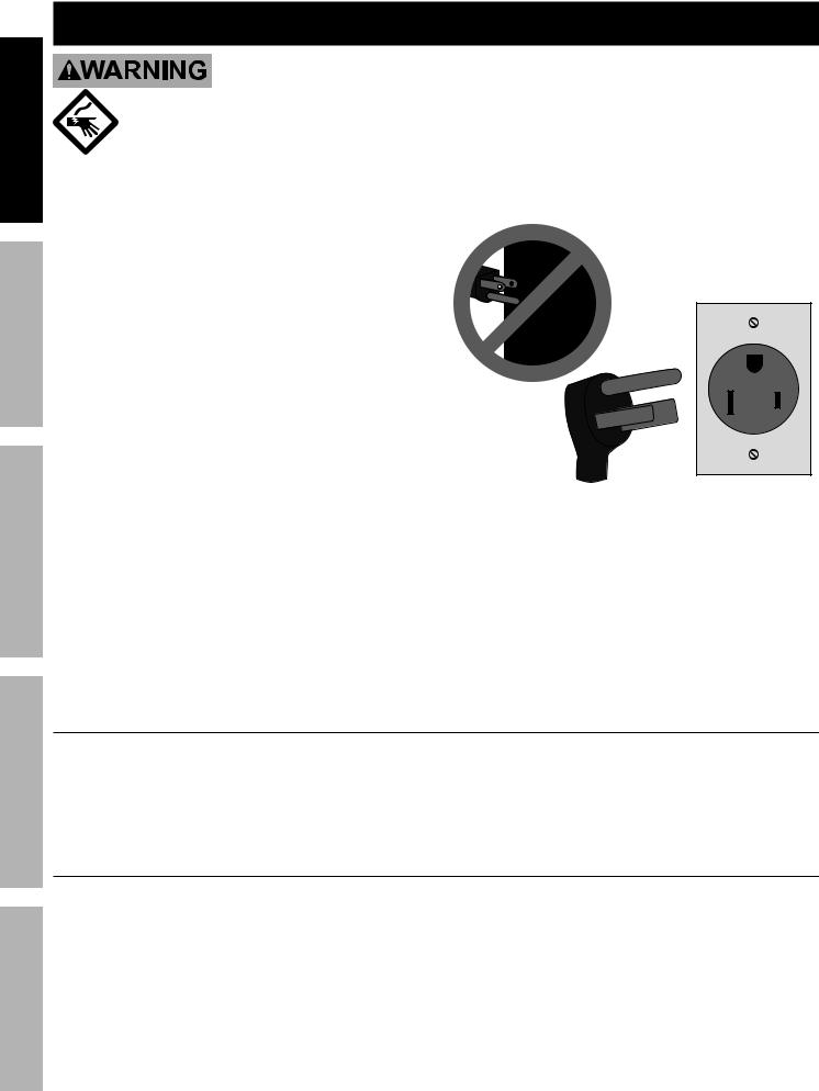
Grounding
TO PREVENT ELECTRIC SHOCK AND DEATH
FROM INCORRECT GROUNDING WIRE CONNECTION:
Check with a qualified electrician if you are in doubt as to whether the outlet is properly grounded. Have a plug installed by a certified electrician.
Do not use the welder if the power cord or plug is damaged. If damaged, have it repaired by a service facility before use. If the plug will not fit the outlet, have a proper outlet installed by a qualified electrician,
do not use adapter plugs.
1.The green wire inside the cord is connected to the grounding system in the welder. The green wire in the cord must be the only wire connected to the welder’s grounding system and must never be attached to an electrically “live” terminal. Never leave the grounding wire disconnected
or modify the Power Cord Plug in any way.
2.Make sure the tool is connected to an outlet having the same configuration as the plug. If the tool must be reconnected for use on a different type of electric circuit, the reconnection should be made by qualified service personnel; and after reconnection, the tool should comply with all local codes and ordinances.
3.A 250 V~ plug will need to be installed by a certified electrician before use.
4.The plug shown (NEMA 6-50p) is for use on a
50 A circuit. A different 250 V~ plug and outlet combination may be used, provided it is rated to handle the electrical requirements of the tool and is installed by a certified electrician.
DO NOT USE 125 V~ PLUG.
NOTE SIZE
DIFFERENCE.
250 V~ 3-Prong Plug (6-50p) and Outlet (6-50r) (for up to 250 V~ and up to 50 A)
Extension Cords
Do not use an extension cord on this welder.
Replacement Cords
1. A qualified electrician can install either of the |
2. |
Do not install a thinner or longer |
|
following UL-listed, 3 wire cords as a replacement |
|
cord on this welder. |
|
cord for this welder: |
3. |
Do not patch cords of any length together for this |
|
12 AWG up to |
6 feet long, |
||
10 AWG up to |
75 feet long, or |
|
item, patches may allow moisture to penetrate |
6 AWG up to 175 feet long. |
|
the insulation, resulting in electric shock. |
|
Page 6 |
For technical questions, please call 1-800-444-3353. |
SKU 68886 |
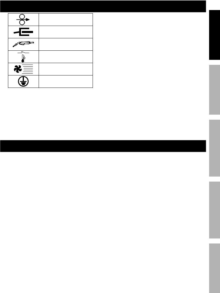
Symbology
Wire Feed (Speed)
Workpiece Ground Cable
Torch Cable
Overheat Shutdown Indicator
Cooling Fan
Housing Ground Point
V~ |
Volts Alternating Current |
A |
Amperes |
|
|
|
|
OCV |
Open Circuit Voltage |
KVA |
Kilovolt Amperes |
(Volts / 1000 * Amperes) |
|
IPM |
Inches Per Minute |
AWG |
American Wire Gauge |
SAFETY
SETUP
Specifications
Power Input |
240 V~, 24 A |
|
Welding Output |
DCEN/DCEP |
|
30-180 A |
||
|
||
Capacity |
18 gauge (0.048″) to 1/4″ (0.25″) mild or stainless steel |
|
Not for welding aluminum |
||
|
||
Rated Duty Cycle |
20% at 140A |
|
(See explanation on page 16) |
||
|
||
Open Circuit Voltage |
34 |
|
KVA |
5.75 |
|
Wire Speed |
30 – 700 IPM |
|
|
Ground: 6′, 7 AWG |
|
Cable Sizes |
Torch: 6′, 7 AWG |
|
Power: 3-wire, 6′ 5″, 12 AWG |
||
|
||
|
6-50P NEMA plug type |
|
Wire Spool Capacity |
up to 10 lb. spool |
|
(one 1 lb. spool of flux core wire included) |
||
|
||
|
Spare Welder Tips (one each for .023″ and .030″– .035″ wire) |
|
Accessories |
Welding Face Shield |
|
|
Combination Wire Brush / Chipping Hammer |
BASIC WELDING
WELDING TIPS
MAINTENANCE
SKU 68886 |
For technical questions, please call 1-800-444-3353. |
Page 7 |
SAFETY
Setup
Read the ENTIRE IMPORTANT SAFETY INFORMATION section at the beginning of this manual including all text under subheadings therein before set up or use of this product.
TO PREVENT SERIOUS INJURY FROM ACCIDENTAL OPERATION:
Turn the Power Switch off and unplug the welder before assembly.
Note: Remove the protective foam and cardboard from the welder before setup.
Face Shield Assembly
SETUP
WELDING BASIC
TIPS WELDING
MAINTENANCE
1.Attach the handle to the Face Shield by lining up the two rectangular tabs on the handle with the corresponding holes in the face shield and
A.press the tabs through the holes and then
B.slide the tabs forward from the back, locking the round tab in place.
B |
B |
Round |
Tab |
A |
A |
Handle
Face Shield
(viewed from front)
2.Wear heavy-duty work gloves, the edges of the filter lens may be sharp. Remove any protective film from both sides of the filter lens. Slide the filter lens into the helmet behind the holding tabs. Make sure that the filter lens fits securely and that light cannot leak around its edges.
Filter Lens
Face Shield
(viewed from back)
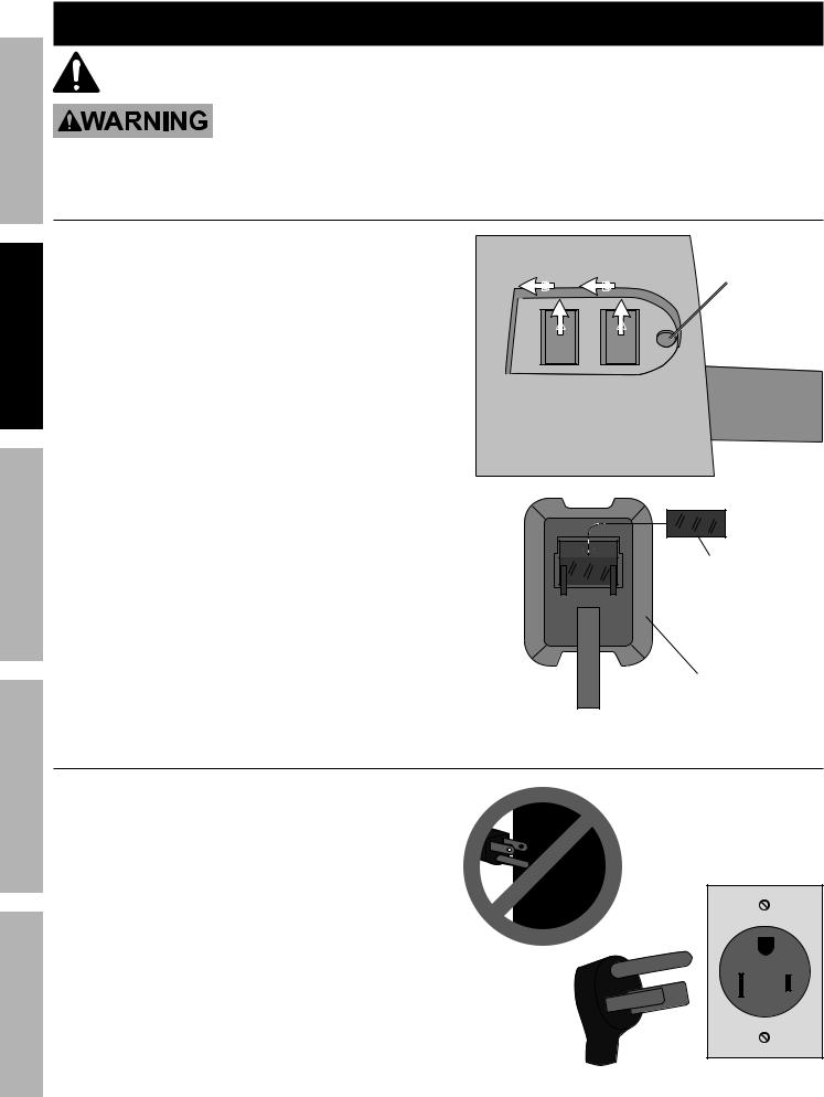
Plug Attachment
1.A 250 V~ plug will need to be installed by a certified electrician before use.
2.The plug shown is for use on a 50 A circuit. A different 250 V~ plug and outlet combination may be used, provided it is rated to handle the electrical requirements of the tool and
is installed by a certified electrician.
Note: Although 125 V~ plugs may look similar, the required plug is much larger, see illustration.
DO NOT USE 125 V~ PLUG.
NOTE SIZE
DIFFERENCE.
250 V~ 3-Prong Plug (6-50p) and Outlet (6-50r) (for up to 250 V~ and up to 50 A)
Page 8 |
For technical questions, please call 1-800-444-3353. |
SKU 68886 |
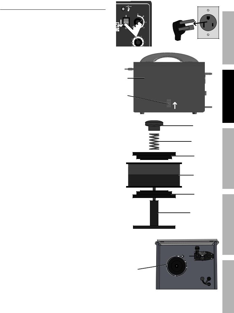
Wire Spool Installation
1.Turn the welder OFF and unplug it before proceeding.
2.Pull up on the door latch, then open the Door.
3.Remove the Spool Knob, Spool Spring, and upper
Spool Plate. If replacing a Spool, remove the old Spool and all remaining wire from the liners.
4.Place the new Wire Spool over the Spool Spindle and on top of the lower Spool Plate as illustrated.
To prevent wire feed problems, set the Spool so that it will unwind clockwise.
5.Secure Spool in place with the upper Spool Plate (narrower end against the Spool),
then the Spool Spring and Spool Knob.
I
ELDER |
SAFETY |
|
Door
door |
SETUP |
|
|
latch |
|
Spool Knob
|
Spool Spring |
WELDING |
|
|
|
|
Upper |
|
|
Spool Plate |
BASIC |
|
Wire Spool |
|
|
|
|
|
Lower |
|
|
Spool Plate |
TIPSWELDING |
|
Spool Spindle |
|
|
|
|
wire must |
|
MAINTENANCE |
unwind this |
|
|
|
|
|
direction |
|
|
SKU 68886 |
For technical questions, please call 1-800-444-3353. |
Page 9 |
SAFETY
6a. Flux Core (Gas-less) Wire Setup:
Remove the two Knobs securing the cables.
Connect the Black Ground Cable to the rear, red, positive Terminal using the Knob.
Connect the Red Torch Cable to the front, black, negative Terminal using the other Knob.
This is the initial setup, called
Direct Current Electrode Negative (DCEN).
6b. Solid Core (Gas Shielded) Wire Setup:
Flux Core (Gas-less) Polarity Setup
|
|
DCEN |
|
Knobs |
|
||
+ |
– |
Torch Polarity: – |
|
Torch |
|||
|
|
||
|
|
(Red) |
|
Ground |
Ground Polarity: + |
||
(Black) |
|
|
|
SETUP
WELDING BASIC
TIPS WELDING
MAINTENANCE
a.Remove the two Knobs securing the cables.
Connect the Black Ground Cable to the front, black, negative Terminal using the Knob.
Connect the Red Torch Cable to the rear, red, positive Terminal using the other Knob.
This is called Direct Current Electrode Positive (DCEP).
b.Determine which type of shielding gas would be appropriate for the welding you will do - see chart on welder.
Solid Core (Gas Shielded) Polarity Setup
|
|
DCEP |
|
Knobs |
|
||
+ |
– |
Torch Polarity: + |
|
Ground |
|||
|
|
||
|
|
(Black) |
|
Torch |
|
Ground Polarity: – |
|
(Red) |
|
|
|
c
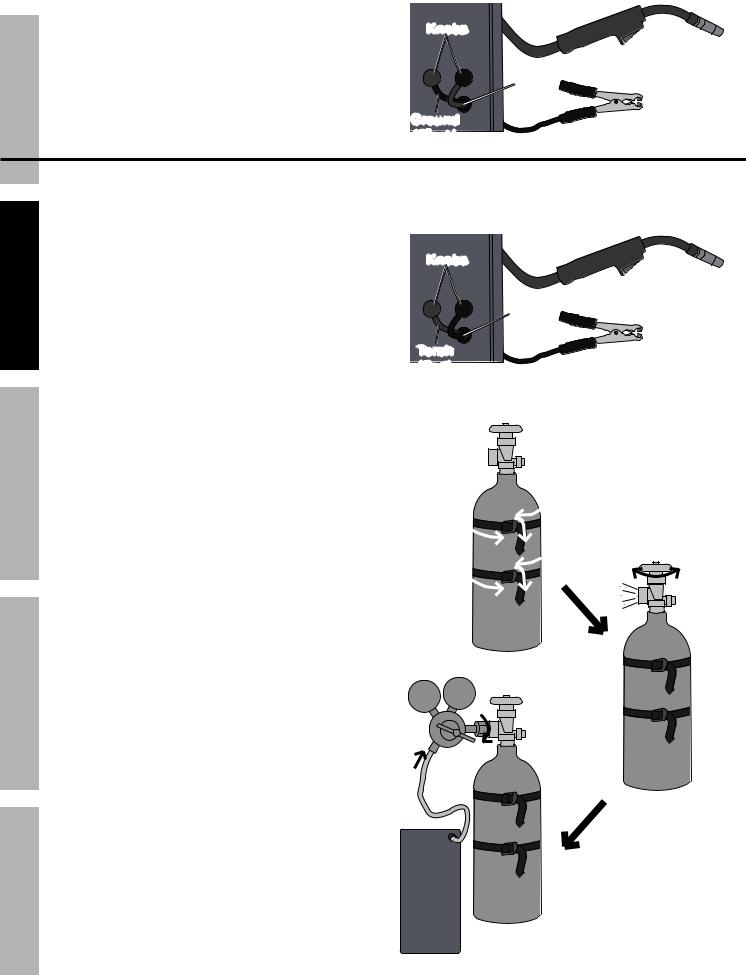
c. With assistance, set the cylinder
(not included) onto a shelf or cart near the welder and secure the cylinder in place with two straps (not included).
d.Remove the protective cap from the cylinder (if present). Stand to the side of the valve opening, and open the valve briefly to blow dust and dirt from the valve opening. Close the cylinder valve.
e. Obtain an appropriate Regulator/Flowmeter |
f |
e |
(not included) and close its valve completely. |
|
|
Thread its inlet connector onto the |
|
|
cylinder and wrench tighten. |
|
|
Note: If the threads do not match, then the Regulator/
Flowmeter is likely for a different type of cylinder/gas.
f.Attach the Gas Hose securely to the outlet of the Regulator/Flowmeter using a hose clamp (sold separately).
Page 10 |
For technical questions, please call 1-800-444-3353. |
Briefly open valve d to clean, then close valve.
SKU 68886
 Loading...