


 Loading...
The Chamberlain Group, Inc.
845 Larch Avenue
Elmhurst, Illinois 60126-1196
www.liftmaster.com
®
GARAGE DOOR OPENER
Models |
3130M 1/3 HP |
3240M 1/2 HP |
For Residential Use Only
Owner’s Manual
■Please read this manual and the enclosed safety materials carefully!
■Fasten the manual near the garage door after installation.
■The door WILL NOT CLOSE unless the Protector System® is connected and properly aligned.
■Periodic checks of the opener are required to ensure safe operation.
■The model number label is located on the front panel of your opener.

TABLE OF CONTENTS
Introduction |
2-5 |
Safety symbol and signal word review . . . . . . . . . . . . . . . 2 Preparing your garage door . . . . . . . . . . . . . . . . . . . . . . . 3 Tools needed. . . . . . . . . . . . . . . . . . . . . . . . . . . . . . . . . . . 3 Planning . . . . . . . . . . . . . . . . . . . . . . . . . . . . . . . . . . . . . . 4 Carton inventory . . . . . . . . . . . . . . . . . . . . . . . . . . . . . . . . 5 Hardware inventory. . . . . . . . . . . . . . . . . . . . . . . . . . . . . . 5
Assembly |
6 |
Fasten rail to the motor unit . . . . . . . . . . . . . . . . . . . |
. . . . 6 |
Installation |
7-22 |
Installation safety instructions . . . . . . . . . . . . . . . . . . . . . 7 Determine the header bracket location . . . . . . . . . . . . . . . 8 Install the header bracket . . . . . . . . . . . . . . . . . . . . . . . . . 9 Attach the rail to the header bracket . . . . . . . . . . . . . . . . 10 Install the Protector System® . . . . . . . . . . . . . . . . . . 11-13 Position the opener. . . . . . . . . . . . . . . . . . . . . . . . . . . . . 14 Hang the opener . . . . . . . . . . . . . . . . . . . . . . . . . . . . . . . 15 Install the door control . . . . . . . . . . . . . . . . . . . . . . . . . . 16 Install the lights . . . . . . . . . . . . . . . . . . . . . . . . . . . . . . . 17 Attach the emergency release rope and handle . . . . . . . . 17 Electrical requirements . . . . . . . . . . . . . . . . . . . . . . . . . . 18 Complete safety reversing sensor installation . . . . . . . . . 18 Fasten the door bracket. . . . . . . . . . . . . . . . . . . . . . . 19-20 Connect the door arm to the trolley . . . . . . . . . . . . . 21-22
Adjustment |
23-25 |
Adjust the UP and DOWN travel limits . . . . . . . . . . . . . . 23 Adjust the force. . . . . . . . . . . . . . . . . . . . . . . . . . . . . . . . 24 Test the safety reversal system . . . . . . . . . . . . . . . . . . . . 25 Test the Protector System®. . . . . . . . . . . . . . . . . . . . . . . 25
Operation |
26-30 |
Operation safety instructions . . . . . . . . . . . . . . . . . . . . . 26 Using your garage door opener . . . . . . . . . . . . . . . . . . . 26 Using the wall-mounted door control . . . . . . . . . . . . . . . 27 To open the door manually . . . . . . . . . . . . . . . . . . . . . . . 27 Care of your garage door opener . . . . . . . . . . . . . . . . . . 28 Having a problem? . . . . . . . . . . . . . . . . . . . . . . . . . . . . . 29 Diagnostic chart . . . . . . . . . . . . . . . . . . . . . . . . . . . . . . . 30
Programming |
31-32 |
To add or reprogram a hand-held remote control . . . . . . 31 To erase all codes . . . . . . . . . . . . . . . . . . . . . . . . . . . . . . 31 3-Button remotes . . . . . . . . . . . . . . . . . . . . . . . . . . . . . . 31 To add, reprogram or change a Keyless Entry PIN . . . . . 32
Repair Parts |
33-34 |
Rail assembly parts. . . . . . . . . . . . . . . . . . . . . . . . . . . . . 33 Installation parts . . . . . . . . . . . . . . . . . . . . . . . . . . . . . . . 33 Motor unit assembly parts . . . . . . . . . . . . . . . . . . . . . . . 34
Accessories |
35 |
Repair Parts and Service |
Back page |
Warranty |
Back page |
INTRODUCTION
Safety Symbol and Signal Word Review
This garage door opener has been designed and tested to offer safe service provided it is installed, operated, maintained and tested in strict accordance with the instructions and warnings contained in this manual.
Mechanical
When you see these Safety Symbols and Signal Words on the following pages, they will alert you to the possibility of serious injury or death if you do not comply with the warnings that accompany them. The hazard may come from something mechanical or from electric shock. Read the warnings carefully.
Electrical
When you see this Signal Word on the following pages, it will alert you to the possibility of damage to your garage door and/or the garage door opener if you do not comply with the cautionary statements that accompany it. Read them carefully.
2
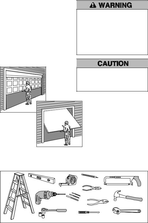
Preparing your garage door
Before you begin:
•Disable locks.
•Remove any ropes connected to garage door.
•Complete the following test to make sure your garage door is balanced and is not sticking or binding:
1.Lift the door about halfway as shown. Release the door. If balanced, it should stay in place, supported entirely by its springs.
2.Raise and lower the door to see if there is any binding or sticking.
If your door binds, sticks, or is out of balance, call a trained door systems technician.
To prevent possible SERIOUS INJURY or DEATH:
•ALWAYS call a trained door systems technician if garage door binds, sticks, or is out of balance. An unbalanced garage door may NOT reverse when required.
•NEVER try to loosen, move or adjust garage door, door springs, cables, pulleys, brackets or their hardware, ALL of which are under EXTREME tension.
•Disable ALL locks and remove ALL ropes connected to garage door BEFORE installing and operating garage door opener to avoid entanglement.
To prevent damage to garage door and opener:
•ALWAYS disable locks BEFORE installing and operating the opener.
•ONLY operate garage door opener at 120V, 60 Hz to avoid malfunction and damage.
Sectional Door
One-Piece Door
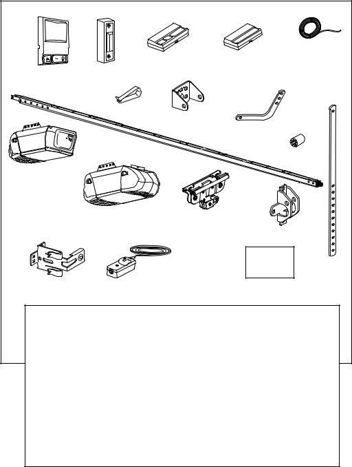
Tools needed
During assembly, installation and adjustment of the opener, instructions will call for hand tools as illustrated below.
Carpenter’s |
|
|
|
Pencil |
|
|
1 2 |
|
|
|
|
Level (optional) |
|
|
|
||
Tape Measure |
|
|
Hack Saw |
||
|
|
|
|
||
|
|
|
|
|
|
|
|
|
|
Wire Cutters |
|
|
Drill |
3/16", 5/16" |
|
|
Claw Hammer |
|
|
and 5/32" Drill Bits |
Pliers |
|
|
Stepladder |
1/2", 3/8" Sockets |
Screwdriver |
Adjustable End Wrench |
||
and Wrench |
|
||||
|
|
|
|
||
|
|
3 |
|
|
|

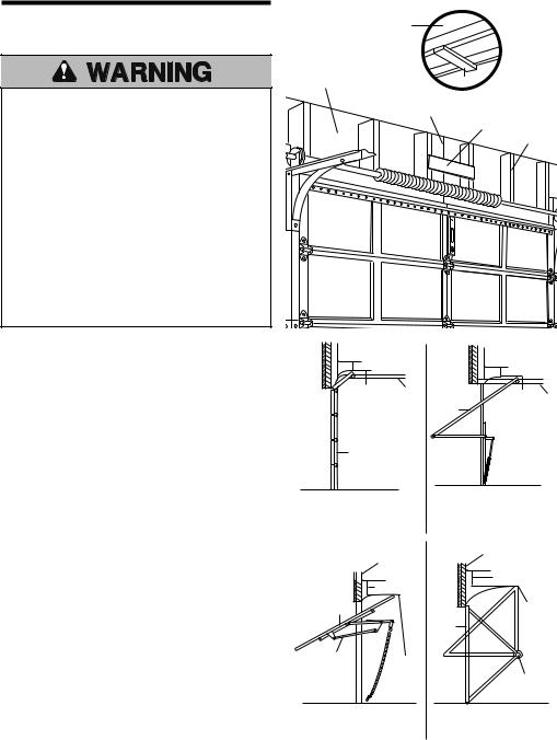
Planning
Identify the type and height of your garage door. Survey your garage area to see if any of the conditions below apply to your installation. Additional materials may be required. You may find it helpful to refer back to this page and the accompanying illustrations as you proceed with the installation of your opener.
SECTIONAL DOOR INSTALLATION
Horizontal and vertical reinforcement is needed for lightweight garage doors (fiberglass, steel, aluminum, door with glass panels, etc.). See page 19 for details.
Header Wall
Vertical |
— |
Centerline |
— — |
of Garage |
|
Door |
|
|
— — — |
|
— — |
FINISHED CEILING
Support bracket & fastening hardware is required.
See page 15.
Rail
 Motor unit
Extension Torsion OR Spring Spring
Wallmounted Door
Control 
 Access Door
|
Safety Reversing Sensor |
|
|
Gap between floor and bottom of |
|
Safety Reversing Sensor |
door must not exceed 1/4" (6 mm). |
|
|
|
|
ONE-PIECE DOOR WITHOUT TRACK |
FINISHED CEILING |
|
Support bracket & fastening hardware is required.
See page 16.
Rail |
Motor unit |
Header Wall
ONE-PIECE DOOR WITH TRACK
Wall-mounted |
Wall-mounted |
|
Door Control |
||
Door Control |
||
|
Access
Door
Access
Door
Safety Reversing Sensor |
|
Safety Reversing Sensor |
Gap between floor and bottom of |
|
|
Safety Reversing Sensor door must not exceed 1/4" (6 mm). |
Safety Reversing |
Gap between floor and bottom of |
|
door must not exceed 1/4" (6 mm). |
|
|
Sensor |
|
|
|
4
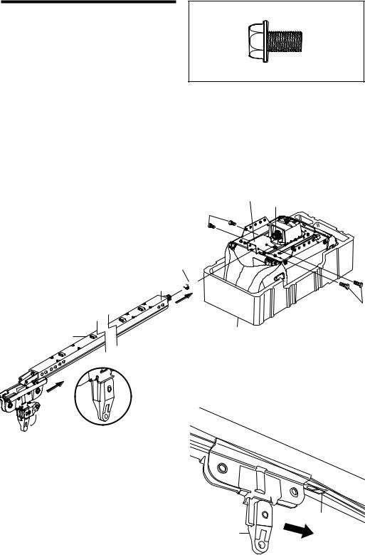
Carton Inventory
Your garage door opener is packaged in two cartons which contain the motor unit and all parts illustrated below. Accessories will depend on the model purchased.
If anything is missing, carefully check the packing material. Parts may be stuck in the foam. Hardware for installation is also listed below.
Model 3240M |
Model 3130M |
Model 3240M (1) |
Model 3130M (1) |
|
|
|
|
||
|
|
|
|
2 Conductor Bell Wire |
|
|
SECURITY ® |
SECURITY ® |
White & White/Red |
|
Lighted Door |
3-Button Remote Control |
1-Button Remote Control |
|
Multi-Function Door |
|
|
||
|
|
|
||
Control Button |
|
|
|
|
Control Panel |
|
|
|
|
|
|
|
|
|
|
|
ONLY |
|
|
|
|
MOUNT |
|
|
|
|
CEILING |
|
|
|
|
UP |
|
|
|
Remote Control |
|
|
|
|
Visor Clip |
Header Bracket |
|
|
|
|
|
|
|
|
|
|
Curved Door |
|
|
|
|
Arm Section |
|
|
|
Rail |
|
Sprocket Coupling |
|
|
|
|
|
Motor Unit with Light Lens |
|
|
|
|
Model 3130M |
|
|
|
|
Motor Unit with 2 Light Lenses |
Trolley |
|
Model 3240M |
||
|
|
The Protector System® |
|
|
(2) Safety Reversing Sensors |
|
Safety Reversing |
(1 Sending Eye and 1 Receiving |
|
Eye) with 2-Conductor White & |
||
Sensor Brackets (2) |
||
White/Black Bell Wire attached |
||
|
Door Bracket
Safety Labels
and Literature Straight Door
Arm Section
RAIL ASSEMBLY
Coupling Sleeve (1)
Hex Bolt 1/4"-20 x 5/8" (4)
Nut 1/4" - 20 (4)
INSTALLATION HARDWARE
Hex Bolt 5/16"-18x7/8" (4)
Lag Screw 5/16"-9x1-5/8" (2)
Lag Screw 5/16"-18x1-7/8" (2) Clevis Pin 5/16"x2-3/4" (1) Clevis Pin 5/16"x1-1/4" (1) Clevis Pin 5/16"x1" (1)
Nut 5/16"-18 (4)
Lock Washer 5/16" (4)
Screw 6ABx1-1/4" (2)
Screw 6-32x1" (2)
Self-Threading Screw 1/4"-14x5/8" (2)
Insulated Staples (30)
Ring Fastener (3)
Drywall Anchors (2)
Carriage Bolt 1/4"-20x1/2" (2)
Wing Nut 1/4"-20 (2)
Rope
Handle
5
ASSEMBLY STEP 1
Fasten the Rail to the Motor Unit
To avoid installation difficulties, do not run the garage door opener until instructed to do so.
To aid in assembly and installation, replace the foam packing around the motor unit. Remove it after Installation Step 4.
•Working on a level surface, align the rail assembly with the motor unit, as shown.
•Slip the coupling over the rail sprocket.
•Slide the rail through the motor unit bracket until the coupling fits securely over the motor unit sprocket.
•Align the two bolt holes in the rail with those in the motor unit bracket. Insert two 1/4"-20x7/16" hex bolts and lock nuts. Tighten securely with a 3/8" socket wrench.
•Turn release arm down to disengage trolley.
•Slide the trolley onto and along the bottom of the rail. Align trolley with rack and turn release arm up to re-engage trolley. Be certain to install it facing correctly: the trolley release arm must be horizontal (lock position).
HARDWARE SHOWN ACTUAL SIZE
Hex Bolt 1/4"-20x7/16"
Motor Unit Motor Unit Bracket
Hex Bolts Sprocket 1/4"-20x7/16"
Coupling
Rail Sprocket 
Hex Bolts 1/4"-20x7/16"
Foam Packaging
Rail Assembly

 Release Arm
Rack
Trolley
To motor unit
6

INSTALLATION
IMPORTANT INSTALLATION INSTRUCTIONS

 WARNING
To reduce the risk of SEVERE INJURY or DEATH:
1.READ AND FOLLOW ALL INSTALLATION WARNINGS AND INSTRUCTIONS.
2.Install garage door opener ONLY on properly balanced and lubricated garage door. An improperly balanced door may NOT reverse when required and could result in SEVERE INJURY or DEATH.
3.ALL repairs to cables, spring assemblies and other hardware MUST be made by a trained door systems technician BEFORE installing opener.
4.Disable ALL locks and remove ALL ropes connected to garage door BEFORE installing opener to avoid entanglement.
5.Install garage door opener 7 feet (2.1 m) or more above floor.
6.Mount emergency release handle 6 feet (1.8 m) above floor.
7.NEVER connect garage door opener to power source until instructed to do so.
8.NEVER wear watches, rings or loose clothing while installing or servicing opener. They could be caught in garage door or opener mechanisms.
9.Install wall-mounted garage door control:
•within sight of the garage door.
•out of reach of children at minimum height of 5 feet (1.5 m).
•away from ALL moving parts of the door.
10.Place entrapment warning label on wall next to garage door control.
11.Place manual release/safety reverse test label in plain view on inside of garage door.
12.Upon completion of installation, test safety reversal system. Door MUST reverse on contact with a 1-1/2" (3.8 cm) high object (or a 2x4 laid flat) on the floor.
7
INSTALLATION STEP 1
Determine the Header Bracket Location
To prevent possible SERIOUS INJURY or DEATH:
•Header bracket MUST be RIGIDLY fastened to structural support on header wall or ceiling, otherwise garage door might NOT reverse when required. DO NOT install header bracket over drywall.
•Concrete anchors MUST be used if mounting header bracket or 2x4 into masonry.
•NEVER try to loosen, move or adjust garage door, springs, cables, pulleys, brackets, or their hardware, ALL of which are under EXTREME tension.
•ALWAYS call a trained door systems technician if garage door binds, sticks, or is out of balance. An unbalanced garage door might NOT reverse when required.
Installation procedures vary according to garage door types. Follow the instructions which apply to your door.
1.Close the door and mark the inside vertical centerline of the garage door.
2.Extend the line onto the header wall above the door.
You can fasten the header bracket within 4 feet (1.22 m) of the left or right of the door center only if a torsion spring or center bearing plate is in the way; or you can attach it to the ceiling (see page 9) when clearance is minimal. (It may be mounted on the
wall upside down if necessary, to gain approximately 1/2" (1 cm).
If you need to install the header bracket on a 2x4 (on wall or ceiling), use lag screws (not provided) to securely fasten the 2x4 to structural supports as shown here and on page 9.
3.Open your door to the highest point of travel as shown. Draw an intersecting horizontal line on the header wall above the high point:
•3" (7.5 cm) above the high point for sectional door and one-piece door with track.
•8" (20 cm) above the high point for one-piece door without track.
This height will provide travel clearance for the top edge of the door.
NOTE: If the total number of inches exceeds the height available in your garage, use the maximum height possible, or refer to page 9 for ceiling installation.
Unfinished Ceiling |
|
OPTIONAL |
|
|
CEILING |
||
|
|
|
|
|
|
|
MOUNT |
|
|
|
FOR |
|
|
|
HEADER |
Header Wall |
2x4 |
|
BRACKET |
|
Vertical Centerline |
|
|
|
of Garage Door |
2x4 |
|
|
|
Structural |
|
|
|
|
|
|
|
|
Supports |
Level 
 (optional)
Header Wall |
|
|
Header Wall |
3" (7.5 cm) |
|
||
|
3" (7.5 cm) |
||
|
|
|
|
Highest |
Track |
|
Highest Track |
Point of |
|
||
|
Door |
||
Travel |
|
Point of |
|
|
|
|
Travel |
Door |
|
|
|
One-piece door with Sectional door with horizontal track curved track
|
Header Wall |
|
Header Wall |
|
|
|
|
|
8" (20 cm) |
|
8" (20 cm) |
|
|
|
|
Door |
|
|
Highest |
|
|
Door |
Point |
|
|
of Travel |
|
|
|
|
|
Jamb |
Highest |
|
|
Hardware |
|
|
|
Point |
|
|
|
|
|
Pivot |
|
|
of Travel |
|
|
One-piece door without track: One-piece door without track: |
|||
jamb hardware |
|
pivot hardware |
|
8
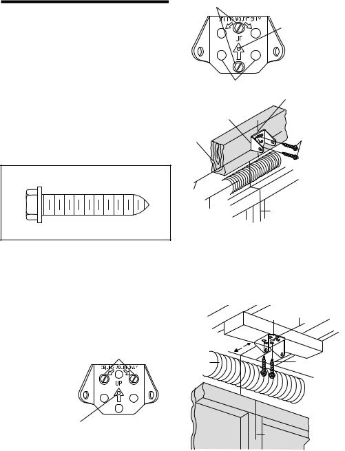
Wall Mounting Holes
INSTALLATION STEP 2
Install the Header Bracket
You can attach the header bracket either to the wall above the garage door, or to the ceiling. Follow the instructions which will work best for your particular requirements. Do not install the header bracket over drywall. If installing into masonry, use concrete anchors (not provided).
WALL HEADER BRACKET INSTALLATION
•Center the bracket on the vertical centerline with the bottom edge of the bracket on the horizontal line as shown (with the arrow pointing toward the ceiling).
•Mark the vertical set of bracket holes (do not use the holes designated for ceiling mount). Drill 3/16" pilot holes and fasten the bracket securely to a structural support with the hardware provided.
Optional Wall
Mounting Holes
Header
- Header Wall - Bracket
2x4 Structural Support
HARDWARE SHOWN ACTUAL SIZE |
|
|
Horizontal |
|
Line |
|
Highest Point |
Lag Screw |
of Garage |
5/16"-9x1-5/8" |
Door Travel |
The nail hole is for positioning only. You must use lag screws to mount the header bracket.
Vertical Centerline
of Garage Door
Lag Screws 5/16"-9x1-5/8"
 Door Spring
- Garage Door -
Vertical Centerline
of Garage Door
CEILING HEADER BRACKET INSTALLATION
•Extend the vertical centerline onto the ceiling as shown.
•Center the bracket on the vertical mark, no more than 6" (15 cm) from the wall. Make sure the arrow is pointing toward the wall. The bracket can be mounted flush against the ceiling when clearance is minimal.
•Mark the side holes. Drill 3/16" pilot holes and fasten bracket securely to a structural support with the hardware provided.
Ceiling Mounting Holes
The nail hole is for positioning only. You must use lag screws to mount the header bracket.
|
- Finished Ceiling - |
|
|
Header |
Vertical Centerline |
|
Bracket |
of Garage Door |
6" (15 cm) |
|
|
Maximum |
|
|
Door |
|
Lag Screws |
Spring |
|
|
|
5/16"-9x1-5/8" |
|
|
|
|
|
|
Header Wall |
Garage Door |
Vertical |
|
|
|
|
|
Centerline |
|
|
of Garage |
|
|
Door |
|
9
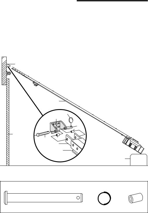
INSTALLATION STEP 3
Attach the Rail to the Header Bracket
• Position the opener on the garage floor below the header bracket. Use packing material as a protective base. NOTE: If the door spring is in the way you’ll need help. Have someone hold the opener securely on a temporary support to allow the rail to clear the spring.
• Position the rail bracket against the header bracket.
• Align the bracket holes and join with a clevis pin as shown.
• Insert a ring fastener to secure.
 Header Wall
Header Bracket

 Rail Bracket
Rail
Ring Fastener
Header Bracket
Spacer
Garage Door
Clevis Pin |
Spacer |
|
|
5/16"x2-3/4" Rail |
|
|
Bracket |
|
Rail |
Opener Carton or
Temporary Support
HARDWARE SHOWN ACTUAL SIZE
Clevis Pin |
Ring Fastener |
Spacer |
|
5/16"x2-3/4" |
|||
|
|
10
INSTALLATION STEP 4
Install The Protector System ®
The safety reversing sensor must be connected and aligned correctly before the garage door opener will move in the down direction.
IMPORTANT INFORMATION ABOUT
THE SAFETY REVERSING SENSOR
When properly connected and aligned, the sensor will detect an obstacle in the path of its electronic beam. The sending eye (with an amber indicator light) transmits an invisible light beam to the receiving eye (with a green indicator light). If an obstruction breaks the light beam while the door is closing, the door will stop and reverse to full open position, and the opener lights will flash
10 times.
The units must be installed inside the garage so that the sending and receiving eyes face each other across the door, no more than 6" (15 cm) above the floor. Either can be installed on the left or right of the door as long as the sun never shines directly into the receiving eye lens.
The mounting brackets are designed to clip onto the track of sectional garage doors without additional hardware.
Be sure power is NOT connected to the garage door opener BEFORE installing the safety reversing sensor.
To prevent SERIOUS INJURY or DEATH from a closing garage door:
•Correctly connect and align the safety reversing sensor. This required safety device MUST NOT be disabled.
•Install the safety reversing sensor so beam is NO HIGHER than 6" (15 cm) above garage floor.
If it is necessary to mount the units on the wall, the brackets must be securely fastened to a solid surface such as the wall framing. Extension brackets (see accessories) are available if needed. If installing in masonry construction, add a piece of wood at each location to avoid drilling extra holes in masonry if repositioning is necessary.
The invisible light beam path must be unobstructed. No part of the garage door (or door tracks, springs, hinges, rollers or other hardware) may interrupt the beam while the door is closing.
|
|
|
|
|
|
|
|
|
|
|
|
|
|
|
|
|
|
|
|
|
|
|
|
|
|
|
|
|
|
|
|
|
|
|
|
|
|
|
|
|
|
|
|
|
|
|
|
|
|
|
|
|
|
|
|
|
|
|
|
|
|
|
|
|
|
|
|
|
|
|
|
|
|
|
|
|
|
|
|
|
|
|
|
|
|
|
|
|
|
|
|
|
|
|
|
|
|
|
|
|
|
|
|
|
|
|
|
|
|
|
|
|
|
|
|
|
|
|
|
|
|
|
|
|
|
|
|
|
|
|
|
|
|
|
|
|
|
|
|
|
|
|
|
|
|
|
|
|
|
|
|
|
|
|
|
|
|
|
|
|
|
|
|
|
|
|
|
|
|
|
|
|
|
|
|
|
|
|
|
|
|
|
|
|
|
|
|
|
|
|
|
|
|
|
|
|
|
|
|
|
|
|
|
|
|
|
|
|
|
|
|
|
|
|
|
|
|
|
|
|
|
|
|
|
|
|
|
|
|
|
|
|
|
|
|
|
|
|
|
|
|
|
|
|
|
|
|
|
|
|
|
|
|
|
|
|
|
|
|
|
|
|
|
|
|
|
|
|
|
|
|
|
|
|
|
|
|
|
|
|
|
|
|
|
|
|
|
|
|
|
|
|
|
|
|
|
|
|
|
|
|
|
|
|
|
|
|
|
|
|
|
|
|
|
|
|
|
|
|
|
|
|
|
|
|
|
|
|
|
|
|
|
|
|
|
|
|
|
|
|
|
|
|
|
|
|
|
|
|
|
|
|
|
|
|
|
|
|
|
|
|
|
|
|
|
|
|
|
|
|
|
|
|
|
|
|
|
|
|
|
|
|
|
|
|
|
|
|
|
|
|
|
|
|
|
|
|
|
|
|
|
|
|
|
|
|
|
|
|
|
|
|
|
|
|
|
|
|
|
|
|
|
|
|
|
|
|
|
|
|
|
|
|
|
|
|
|
|
|
|
|
|
|
|
|
|
|
|
|
|
|
|
|
|
|
|
|
|
|
|
|
|
|
|
|
|
|
|
|
|
|
|
|
|
|
|
|
|
|
|
|
|
|
|
|
|
|
|
|
|
|
|
|
|
|
|
|
|
|
|
|
|
|
|
|
|
|
|
|
|
|
|
|
|
|
|
|
|
|
|
|
|
|
|
|
|
|
|
|
|
|
|
|
|
|
|
|
|
|
|
|
|
|
|
|
|
|
|
|
|
|
|
|
|
|
|
|
|
|
|
|
|
|
|
|
|
|
|
|
|
|
|
|
|
|
|
|
|
|
|
|
|
|
|
|
|
|
|
|
|
|
|
|
|
|
|
|
|
|
|
|
|
|
|
|
|
|
|
|
|
|
|
|
|
|
|
|
|
|
|
|
|
|
|
|
|
|
|
|
|
|
|
|
|
|
|
|
|
|
|
|
|
|
|
|
|
|
|
|
|
|
|
|
|
|
|
|
|
|
|
|
|
|
|
|
|
|
|
|
|
|
|
|
|
|
|
|
|
|
|
|
|
|
|
|
|
|
|
|
|
|
|
|
|
|
|
|
|
|
|
|
|
|
|
|
|
|
|
|
|
|
|
|
|
|
|
|
|
|
|
|
|
|
|
|
|
|
|
|
|
|
|
|
|
Safety Reversing Sensor |
Invisible Light Beam |
|
|
|
|
|
|
|
|
|
|
|
|
|
|
|
|
Safety Reversing Sensor |
||||||||||||||||||||||||||||||
6" (15 cm) max. |
Protection Area |
|
|
|
|
|
|
|
|
|
|
|
|
|
|
|
|
6" (15 cm) max. |
||||||||||||||||||||||||||||||
above floor |
|
|
|
|
|
|
|
|
|
|
|
|
|
|
|
|
|
|
|
|
|
|
|
|
|
|
|
|
|
|
|
above floor |
||||||||||||||||
Facing the door from inside the garage
11
Loading...