


 Loading...
 ANACOM, INC.
AnaSat® SSPA Series
Operating Manual
Ku-Band
SEKu-Band
EC-Band
SEC-Band

You have just received an AnaSat® SSPA (Solid-State Power Amplifier), a cost-effective product with no compromise on quality and reliability. This product should provide tireless performance in any reasonable operating environment. Note that this product is transmit only, and does not include a Block Down-Converter, which will have to be obtained separately.
We, at ANACOM, have taken great care to provide a convenient, easy-to-use product in a single package. Should a situation arise beyond the operator’s control, just give us a telephone call. Many situations can be diagnosed and solved by ANACOM’s trained customer-service personnel over the phone.
If you have any questions, require technical assistance or training please call ANACOM directly at (408) 748-7800 or FAX to us at (408) 748-7801. You can also send e-mail to techsupport@anacominc.com and one of our engineers will contact you.
ANACOM, INC.
3000 Tasman Drive
Santa Clara, CA 95054
Tel: (408) 748-7800
Fax: (408) 748-7801
©2006 AnaCom, Inc. All rights reserved. The information furnished by AnaCom, Incorporated, in this publication is believed to be accurate and reliable. However, no responsibility is assumed by AnaCom for its use, nor any infringements of patents or other rights of third parties resulting from its use. No license is granted by implication or otherwise under any patent or patent right of AnaCom, Inc. AnaCom reserves the right to change circuitry and specifications at any time without prior notice.
The following terms are trademarks of their respective holders: AnaSat, AnaCom, Inc.
Polyswitch Teflon Duroid INTELSAT
ANACOM AnaSat® SSPA

3000 Tasman Drive, Santa Clara, CA 95054
Tel: (408) 748 7800 Fax: (408) 748 7801
3133501
Operating Manual
for the
AnaSat®-Series SSPA
Table of Contents |
|
Table of Contents................................................................................................................. |
3 |
Introduction.......................................................................................................................... |
6 |
Typical Operating Parameters – AnaSat SSPAs...................................................................... |
7 |
Installation............................................................................................................................ |
8 |
Unpacking................................................................................................................................ |
8 |
Tools and Test Equipment..................................................................................... |
8 |
Safety Precautions.................................................................................................................... |
8 |
General.................................................................................................................. |
8 |
Power Supply......................................................................................................... |
8 |
Transmitter............................................................................................................. |
8 |
Power Amplifier...................................................................................................... |
9 |
Site Considerations .................................................................................................................. |
9 |
Antenna ................................................................................................................. |
9 |
Power Requirements ............................................................................................. |
9 |
SSPA Mounting Considerations ............................................................................................ |
10 |
SSPA Mounting ..................................................................................................................... |
10 |
Grounding............................................................................................................ |
10 |
Cable and Waveguide Connections ................................................................................... |
14 |
Cabling Requirements ......................................................................................... |
14 |
AC Power............................................................................................................. |
14 |
Transmitter Feed ................................................................................................. |
15 |
Driver Feed.......................................................................................................... |
15 |
Final Check.......................................................................................................... |
16 |
Water Resistance Wrap....................................................................................... |
16 |
Operation............................................................................................................................ |
17 |
Frequency Programming ..................................................................................... |
17 |
Antenna Adjustment ............................................................................................ |
17 |
Transmit Power Adjustment................................................................................. |
17 |
ANACOM AnaSat® SSPA

|
3133501 |
Maintenance ....................................................................................................................... |
18 |
Fan Replacement.................................................................................................................... |
18 |
Alarm Relay Closure.......................................................................................................... |
19 |
Monitored Values................................................................................................. |
19 |
Data Terminal Connection................................................................................................. |
19 |
Terminal Display .................................................................................................. |
19 |
RS232 Serial Port Weather-tight Connector...................................................................... |
20 |
RS485/RS232 Selection ...................................................................................... |
21 |
Emissions and Immunity Regulation Conformance .......................................................... |
22 |
Standards Met: .................................................................................................... |
22 |
LIMITED WARRANTY ................................................................................................... |
23 |
ANACOM AnaSat® SSPA |
4 |
3133501
AnaAat® SSPA Quick Start Guide
1.Mount the SSPA on the antenna.
2.Connect the cables for RF input, and RF output (waveguide).
3.If needed, connect the M&C or PA MONITOR to the driver or Protection Switch.
4.Connect AC power, nominal 120 or 240 VAC.
There are no settings that need adjustment.
The SSPA is factory set for a gain equal to the P1dB value.
For monitoring the performance of the SSPA, there are two methods
1.Connect a computer to the RS232 port using the cable provided, and the Supervisor software. Now you can see a status of the SSPA digital and analog monitored points. The gain is fixed and cannot be changed. You can MUTE the SSPA with the command TX OFF/ON.
2.Connect a cable (user provided) to the PA MONITOR connector. This will provide:
A.Pin 1 is used to MUTE the SSPA by grounding this pin.
B.Pin 2 is used to show a summary fault in the SSPA (0 volts). 5 volts is normal.
C.Pin 3 is used to show an analog voltage that changes as output power changes.
D.Pin 4 is used to show the SSPA internal temperature in analog form.
E.Pin 5 is not used.
F.Pin 6 is ground.
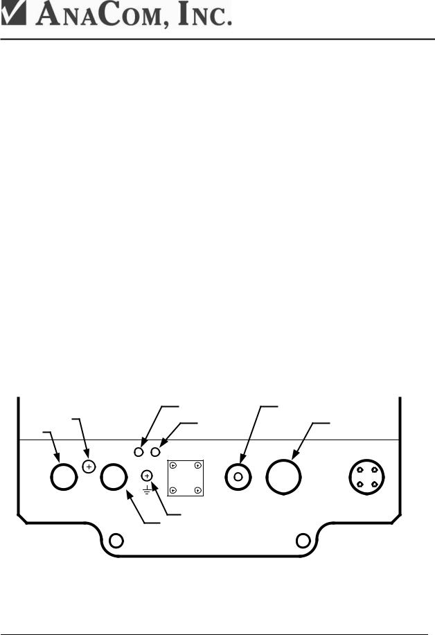
Drawing of required cable connections
Monitor |
DO NOT OPEN |
"Alarm" RED LED |
RF INPUT |
|
||
Pressure Test port |
|
Serial ports & Alarm Relay |
||||
analog |
"OK" Green LED |
|||||
|
|
|||||
points |
|
|
|
|
|
|
|
|
ALARM |
POWER |
|
|
|
|
6 |
6 |
|
18 |
|
|
|
PIN |
PIN |
|
PIN |
|
|
PA MONITOR |
RS232 |
TXIN |
M & C |
100~250VAC |
||
|
|
|
Ground Lug |
|
|
|
|
|
|
Serial Port |
|
|
|
ANACOM AnaSat® SSPA |
5 |
3133501
Introduction
The AnaSat® VSAT series of SSPAs are designed for continuous outdoor duty in all types of environments. Ideally suited for SCPC, MCPC, DAMA, and VoIP applications. Designed to interface with a 0 dBm driver, the AnaSat® VSAT SSPA may be used in a wide variety of communication networks.
The C-band members of the AnaSat® SSPA family transmit in the 6 GHz frequency range. The Ku-band members of the SSPA® SSPA family transmit in the 14 GHz frequency.
The AnaSat® VSAT SSPAs incorporate a solid-state power amplifier, M&C function, and a universal power supply, all in a small, highly integrated outdoor package. The only cabling required to the indoor plant are the RF and AC power cables.
The Power Amplifier (PA) uses Internally-Matched Field-Effect Transistors (IMFET) to achieve highly linear power and gain with minimal intermodulation distortion (IMD) products.
AnaSat® SSPAs use a wide input voltage (100 to 240VAC, 47 to 63Hz) switching power supply to develop the +13V used as the internal power source for the Power amplifier. An internal circuit senses the input voltage range being used and automatically switches to the appropriate mode. The AC input is connected via a 4-pin circular connector.
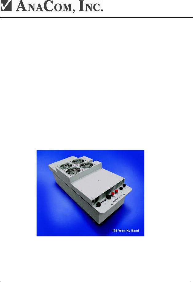
Shown in Figure 1 below is a 125W Ku-Band AnaSat® SSPA.
Figure 1 - 125 Watt Ku-Band SSPA
ANACOM AnaSat® SSPA |
6 |

3133501
Typical Operating Parameters – AnaSat SSPAs
EC/SEC-Band |
|
|
|
|
Ku/SEKu-Band |
|
|
|
||
1 dB Compression Point |
10W: 40 dBm |
40 dB |
TX Gain |
|
|
1 dB Compression Point |
8W: 39 dBm |
39 dB |
TX Gain |
|
|
20W: 43 dBm |
43 dB |
|
|
|
|
16W: 42 dBm |
42 dB |
|
|
|
30W: 44.8 dBm |
44.8 dB |
|
|
20W: 43 dBm |
43 dB |
||||
|
40W: 46 dBm |
46 dB |
|
|
23W: 43.6 dBm |
43.6 dB |
||||
|
50W: 47 dBm |
47 dB |
|
|
25W: 44 dBm |
44 dB |
||||
|
60W: 47.8 dBm |
47.8 dB |
|
|
40W: 46 dBm |
46 dB |
||||
|
70W: 48.5 dBm |
48.5 dB |
|
|
50W: 47 dBm |
47 dB |
||||
|
80W: 49 dBm |
49 dB |
|
|
60W: 49 dBm |
49 dB |
||||
|
100W: 50 dBm |
50 dB |
|
|
80W: 49.75 dBm |
49.75 dB |
||||
|
125W: 51 dBm |
51 dB |
|
|
100W: 50 dBm |
50 dB |
||||
|
150W: 51.8 dBm |
51.8 dB |
|
|
125W: 51 dBm |
51 dB |
||||
|
180W: 52.6 dBm |
52.6 dB |
|
|
|
|
|
|
||
|
200W: 53 dBm |
53 dB |
|
|
|
|
|
|
||
|
|
|
|
TX Level Flatness |
6dBp-p max / 500 MHz |
|
|
||
|
|
|
|
|
|
|
|
|
|
|
|
|
|
TX Input |
N-Type Connector |
|
|
|
|
|
|
|
|
TX Input RF Impedance |
50 Ω (75 Ω is optional) |
|
|
||
|
|
|
|
|
|
|
|
|
|
|
|
|
|
TX Input Level |
0 dBm |
|
|
|
|
Transmit RF |
|
EC - 5.850 to 6.425 GHz |
|
Transmit RF |
|
Ku - 14.0 to 14.5 GHz |
|||
|
|
SEC - 5.850 to 6.650 GHz |
|
|
|
SEKu – 13.75 to 14.5 GHz |
|||
CPR-137 Flange (Threaded & Grooved): 30W, 50W and higher |
|
WR-75 Flange (Threaded & Grooved) all power levels |
|||||||
N-Type Connector: |
|
10W, 20W, 40W |
|
|
|
|
|
||
|
|
|
|
Spurious |
-50 dBc max, + - 500 Hz: - 45 dBc |
|
|||
|
|
|
|
|
|
|
|||
|
|
|
|
Alarm Relays |
FORM C for Summary Alarm; Isolated |
|
|||
|
|
|
|
Temperature Range |
-40C to +50C operational |
|
|
||
|
|
|
|
|
|
-40C to +75C storage |
|
|
|
|
|
|
|
Altitude |
10,000 feet (3,048 meters) max |
|
|
||
|
|
|
|
Rain |
20 inches per hour |
|
|
|
|
|
|
|
|
Wind |
150 miles per hour |
|
|
|
|
|
|
|
|
Vibration |
1.0 g random operational, |
|
|
||
|
|
|
|
|
|
2.5 g random survival |
|
|
|
|
|
|
|
Shock |
10 g operational, 40 g survival |
|
|
||
|
|
|
|
Power |
100 to 250 VAC; 47 to 63 Hz |
|
|
||
Typical Power Consumption / Weight |
|
|
Typical Power Consumption / Weight |
|
|||||
10W: |
125VA / 32 lb. (15kg) |
70W: |
570VA / 57 lb. (27kg) |
|
8W: 160VA / 28 lb. (13kg) |
40W: 770VA / 67 lb. (31kg) |
|||
20W: |
230VA / 39 lb. (18kg) |
80W: |
570VA/ 60 lb. (28kg) |
|
16W: 270VA / 37 lb. (17kg) |
50W: 800VA / 67 lb. (31kg) |
|||
30W: |
280VA / 57 lb. (26kg) |
100W: 760VA / 75 lb. (34kg) |
|
20W: 290VA / 40 lb. (18kg) |
60W: 850VA / 67 lb. (31kg) |
||||
40W: |
390VA / 45 lb. (21kg) |
125W: 1070VA / 100 lb. (46kg) |
|
23W: 300VA / 40 lb. (18kg) |
80W: 1430VA / 125 lb. (57kg) |
||||
50W: |
390VA / 57 lb. (26kg) |
150W: 1070VA / 100 lb. (46kg) |
|
25W: 300VA / 40 lb. (18kg)) |
100W: 1600VA / 125 lb. (57kg) |
||||
60W: |
400VA / 57 lb. (26kg |
180W: 1400VA / 134 lb. (61kg) |
|
|
|
125W: 1640VA / 125 lb. (57kg) |
|||
|
|
|
200W: 1400VA / 134 lb. (61kg) |
|
|
|
|
|
|
SSPA Size |
|
|
|
|
SSPA Size |
|
|
|
|
10W |
|
21.6" x 9" x 11.6" |
(549 x 229 x 295 mm) |
|
|
|
|
|
|
20W |
|
21.6” x 9” x 13.5” |
(549 x 229 x 343 mm) |
|
8W |
21.6" x 9" x 11.6" |
(549 x 229 x 295 mm) |
||
40W |
|
21.6" x 9" x 14" |
(549 x 229 x 356 mm) |
|
16W, 20W, 23W, 25W |
21.6” x 9” x 13” |
(549 x 229 x 330 mm) |
||
30, 50, 60, 70W |
21.6" x 9" x 15" |
(549 x 229 x 381 mm) |
|
40W, 50W, 60W |
21.6" x 13" x 13.6" (549 x 330 x 353 mm) |
||||
80W |
|
21.6" x 9" x 16" |
(549 x 229 x 407 mm) |
|
80W, 100W, 125W |
38” x 13” x 12.5” |
(965 x 330 x 318 mm) |
||
100W |
|
21.6" x 13" x 14" |
(549 x 330 x 356 mm) |
|
|
|
|
|
|
125,150,180,200W |
38" x 13" x 12.5" |
(965 x 330 x 381 mm) |
|
|
|
|
|
||
ANACOM AnaSat® SSPA |
7 |
Loading...