


T R-410A
40RU
Packaged Air-Handling Units
60 Hz
®
with Puron
(R-410A) Refrigerant
Sizes 25, 28, 30
Installation, Start-Up and
Service Instructions
TABLE OF CONTENTS
SAFETY CONSIDERATIONS . . . . . . . . . . . . . . . . . . . . . . . 1
PRE-INST ALLA TION . . . . . . . . . . . . . . . . . . . . . . . . . . . . . . 2
Moving and Storage. . . . . . . . . . . . . . . . . . . . . . . . . . . . . 2
Rigging. . . . . . . . . . . . . . . . . . . . . . . . . . . . . . . . . . . . . . . . 2
INSTALLATION . . . . . . . . . . . . . . . . . . . . . . . . . . . . . . . . 2–20
General. . . . . . . . . . . . . . . . . . . . . . . . . . . . . . . . . . . . . . . . 2
Uncrating. . . . . . . . . . . . . . . . . . . . . . . . . . . . . . . . . . . . . . 2
Accessories . . . . . . . . . . . . . . . . . . . . . . . . . . . . . . . . . . . . 2
Unit Positioning . . . . . . . . . . . . . . . . . . . . . . . . . . . . . . . . 9
Unit Isolation. . . . . . . . . . . . . . . . . . . . . . . . . . . . . . . . . . 11
Refrigerant and Chilled Water Piping Access . . . . . . 11
Refrigerant Piping . . . . . . . . . . . . . . . . . . . . . . . . . . . . . 11
Chilled Water Piping . . . . . . . . . . . . . . . . . . . . . . . . . . . 15
Condensate Drain . . . . . . . . . . . . . . . . . . . . . . . . . . . . . . 16
Fan Motors and Drives . . . . . . . . . . . . . . . . . . . . . . . . . 16
Power Supply and Wiring . . . . . . . . . . . . . . . . . . . . . . . 17
Connecting Ductwork . . . . . . . . . . . . . . . . . . . . . . . . . . 20
Return-Air Filters . . . . . . . . . . . . . . . . . . . . . . . . . . . . . . 20
START-UP. . . . . . . . . . . . . . . . . . . . . . . . . . . . . . . . . . . . . . . . 21
SERVICE. . . . . . . . . . . . . . . . . . . . . . . . . . . . . . . . . . . . . . 21–34
Panels . . . . . . . . . . . . . . . . . . . . . . . . . . . . . . . . . . . . . . . . 21
Fan Motor Lubrication. . . . . . . . . . . . . . . . . . . . . . . . . . 21
Fan Shaft Bearings . . . . . . . . . . . . . . . . . . . . . . . . . . . . . 21
Centering Fan Wheel . . . . . . . . . . . . . . . . . . . . . . . . . . . 22
Fan Shaft Position Adjustment. . . . . . . . . . . . . . . . . . . 22
Individual Fan Wheel Adjustment . . . . . . . . . . . . . . . . 22
Fan Belts . . . . . . . . . . . . . . . . . . . . . . . . . . . . . . . . . . . . . 22
Fan Rotation . . . . . . . . . . . . . . . . . . . . . . . . . . . . . . . . . . 22
Fan Pulley Alignment . . . . . . . . . . . . . . . . . . . . . . . . . . 23
Pulley and Drive Adjustment . . . . . . . . . . . . . . . . . . . . 23
Condensate Drains . . . . . . . . . . . . . . . . . . . . . . . . . . . . . 23
Return-Air Filters . . . . . . . . . . . . . . . . . . . . . . . . . . . . . . 23
Chilled Water Coil Freeze Protection . . . . . . . . . . . . 23
Coil Removal . . . . . . . . . . . . . . . . . . . . . . . . . . . . . . . . . 23
Cleaning Cooling Coil. . . . . . . . . . . . . . . . . . . . . . . . . . 23
Cleaning Insulation . . . . . . . . . . . . . . . . . . . . . . . . . . . . 23
Replacing Filters. . . . . . . . . . . . . . . . . . . . . . . . . . . . . . . 24
START-UP CHECKLIST . . . . . . . . . . . . . . . . . . . CL-1, CL-2
SAFETY CONSIDERATIONS
Improper installation, adjustment, alteration, service,
maintenance, or use can cause explosion, fire, electrical shock
or other conditions which may cause personal injury or
property damage. Consult a qualified installer, service agency,
or your distributor or branch for information or assistance. The
qualified installer or agency must use factory-authorized kits or
accessories when modifying this product. Refer to the
individual instructions package
Follow all safety codes. Wear safety glasses and work gloves.
Use quenching cloths for brazing operations and have a fire
extinguisher available. Read these instructions thoroughly and
follow all warnings or cautions attached to the unit. Consult
local building codes and appropriate national electrical codes
(in USA, ANSI/NFPA70, National Electrical Code (NEC); in
Canada, CSA C22.1) for special requirements.
It is important to recognize safety information. This is the
safety-alert symbol . When you see this symbol on the unit
and in instructions or manuals, be alert to the potential for
personal injury.
Understand the signal words DANGER, WARNING,
CAUTION, and NOTE. These words are used with the
safety-alert symbol. DANGER identifies the most serious
hazards which will result in severe personal injury or death.
WARNING signifies hazards which could result in personal
injury or death. CAUTION is used to identify unsafe practices,
which may result in minor personal injury or product and
property damage. NOTE is used to highlight suggestions
which will result in enhanced installation, reliability, or
operation.
ELECTRICAL SHOCK HAZARD
LEGEND
TXV — Thermostatic Expansion Valve
Failure to follow this warning could cause personal injury
or death.
Before performing service or maintenance operations on
unit, always turn off main power switch to unit and install
lockout tag. Unit may have more than one power switch.
UNIT OPERA TION AND SAFETY HAZARD
Failure to follow this warning could cause personal injury,
death and/or equipment damage.
Puron® (R-410A) refrigerant systems operate at higher
pressures than standard R-22 systems. Do not use R-22
service equipment or components on Puron refrigerant
equipment.
PERSONAL INJURY AND ENVIRONMENTAL
HAZARD
Failure to follow this warning could cause personal injury
or death.
Relieve pressure and recover all refrigerant before system
repair or final unit disposal.
Wear safety glasses and gloves when handling refrigerants.
Keep torches and other ignition sources away from
refrigerants and oils.
CUT HAZARD
Failure to follow this caution may result in personal injury.
Sheet metal parts may have sharp edges or burrs. Use care
and wear appropriate protective clothing, safety glasses and
gloves when handling parts and servicing 40RU units.
4. This installation must conform with local building codes
and with the NEC (National Electrical Code) or ANSI
(American National Standards Institute)/NFPA (National
Fire Protection Association) latest revision. Refer to
provincial and local plumbing or wastewater codes and
other applicable local codes.
Moving and Storage — To transfer unit from truck to
storage site, use a fork truck. Do not stack units more than
2 high during storage. If unit is to be stored for more than
2 weeks before installation, choose a level, dry storage site free
from vibration. Do not remove plastic wrap or skid from unit
until final installation.
Rigging — All 40RU Series units can be rigged by using
the shipping skid. Units are shipped fully assembled. Do not
remove shipping skids or protective covering until unit is ready
for final placement; damage to bottom panels can result. Use
slings and spreader bars as applicable to lift unit.
INSTALLATION
General — Allow 2
clearance and airflow. For units equipped with an economizer,
refer to the accessory installation instructions for additional
clearance requirements. Be sure floor, wall, or ceiling can
support unit weight (T ables 1A – 1D). See Fig. 2A and Fig. 2B
for dimensions.
Uncrating — Move unit as near as possible to final loca-
tion before removing shipping skid.
Remove metal banding, top skid, and plastic wrap. Examine
unit for shipping damage. If shipping damage is evident, file
claim with transportation agency. Remove base skid just prior
to actual installation.
Check nameplate information against available power supply
and model number description in Fig. 3.
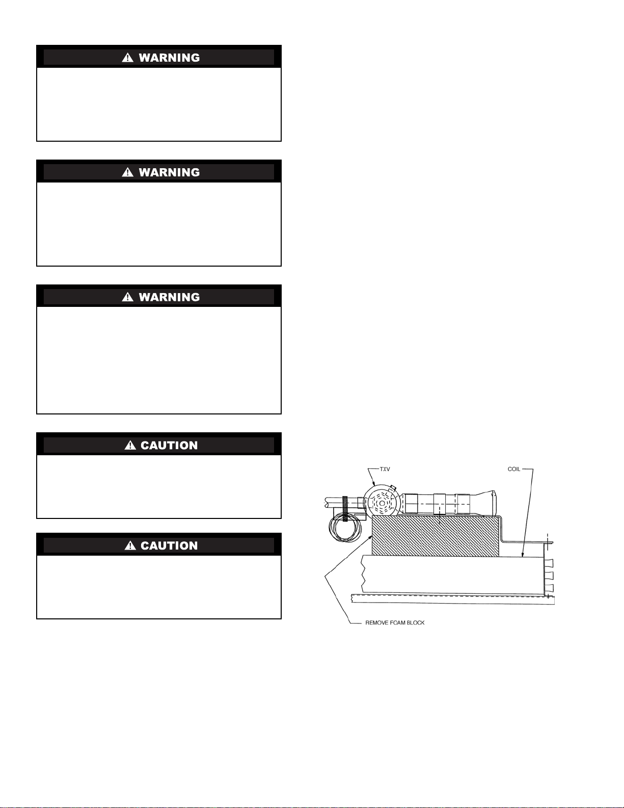
NOTE: Be sure to remove the styrofoam shipping pad from
the thermostatic expansion valve (TXV). Verify that it has
been removed. See Fig. 1.
1
/2 ft at front and side of unit for service
UNIT OPERA TION HAZARD
Failure to follow this caution could cause equipment
damage.
Ensure voltage listed on unit data plate agrees with
electrical supply provided for the unit.
PRE-INSTALLATION
1. The power supply (v, ph, and Hz) must correspond to that
specified on unit rating plate.
2. The electrical supply provided by the utility must be sufficient to handle load imposed by this unit.
3. Refer to Installation, General section (page 2) and
Fig. 2A and Fig. 2B for locations of electrical inlets, condensate drain, duct connections, and required clearances
before setting unit in place.
Fig. 1 — Foam Block Location
Accessories — Refer to instructions shipped with each
accessory for specific information.
2

LEGEND
TXV — Thermostatic Expansion Valve
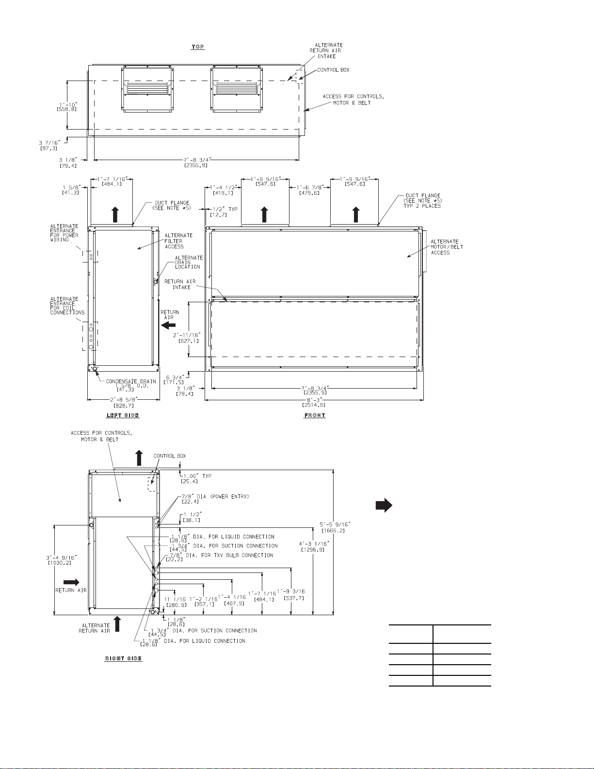
NOTES:
1. Dimensions in [ ] are in millimeters.
2. Direction of airflow.
3. Recommended clearance:
• Rear: 3 in. (76 mm)
• Front: 2 ft, 6 in. (762 mm)
• Right Side: 2 ft, 6 in. (762 mm)
• Left Side: 2 ft, 6 in. (762 mm)
• Local codes or jurisdiction may
prevail.
4. Liquid piping not supplied by Carrier.
5. Duct flange is factory-supplied and field-
installed.
UNIT
UNIT WEIGHT
lb (kg)
40RUA*25 730 (331)
40RUS*25 683 (310)
Fig. 2A — Dimensions – Size 25
3
UNIT
UNIT WEIGHT
lb (kg)
40RUA*28 1050 (477)
40RUA*30 1062 (482)
40RUS*28 1035 (469)
40RUS*30 1042 (473)
LEGEND
TXV — Thermostatic Expansion Valve
NOTES:
1. Dimensions in [ ] are in millimeters.
2. Direction of airflow.
3. Recommended clearance:
• Rear: 3 in. (76 mm)
• Front: 2 ft, 6 in. (762 mm)
• Right Side: 2 ft, 6 in. (762 mm)
• Left Side: 2 ft, 6 in. (762 mm)
• Local codes or jurisdiction may
prevail.
4. Liquid piping not supplied by Carrier.
5. Duct flange is factory-supplied and field-
installed.
6. 40RUS may require alternate or additional
field favricated poping access holes
Fig. 2B — Dimensions – Sizes 28 and 30
4
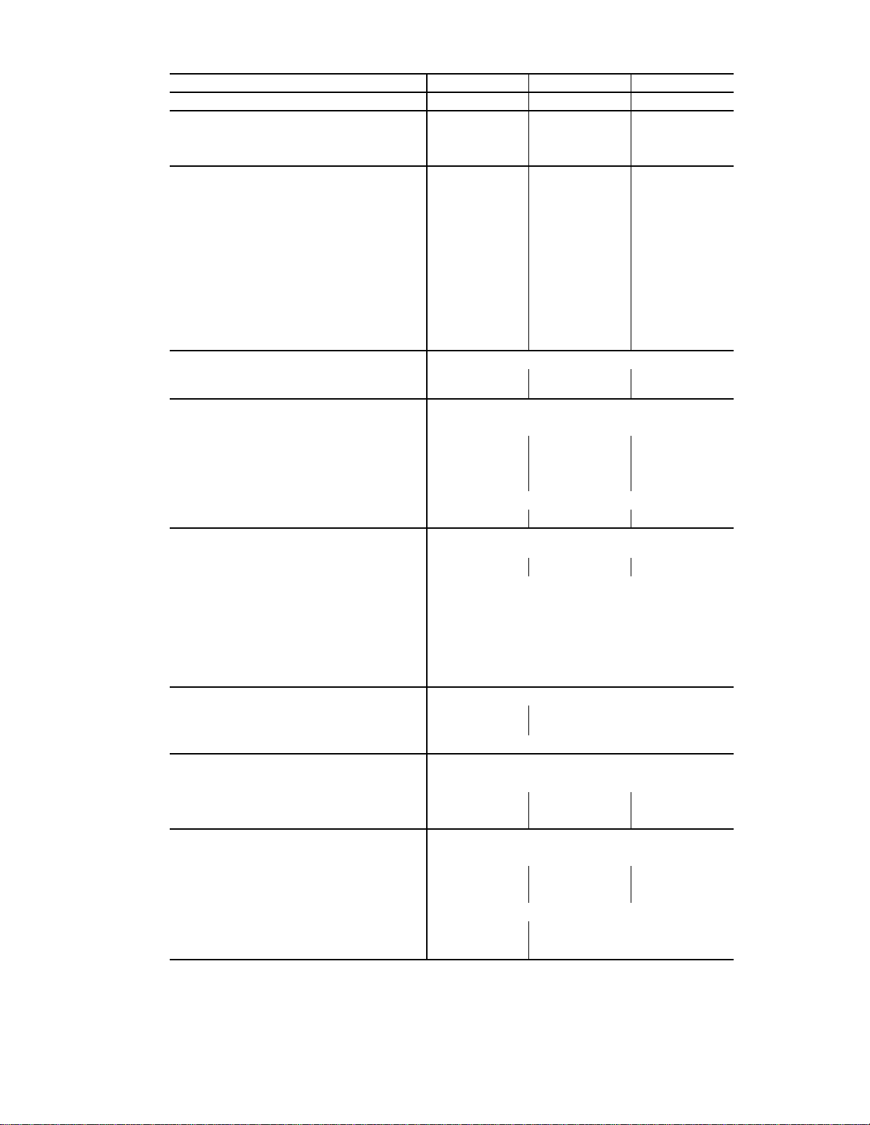
Table 1A — 40RUA Physical Data, English — Cooling Units
UNIT 40RUA* 25 28 30
NOMINAL CAPACITY (Tons) 20 25 30
OPERATING WEIGHT (lb)
Base Unit with TXV 730 1050 1062
Plenum 225 325 325
FANS
Qty...Diam. (in.) 2...15 2...18 2...18
Nominal Airflow (cfm) 8,000 10,000 12,000
Airflow Range (cfm) 6,000 – 10,000 7,500 – 12,500 9,000 – 15,000
Nominal Motor Hp (Standard Motor)
208/230-3-60 and 460-3-60 5.0 7.5 10.0
575-3-60 5.0 7.5 10.0
Motor Speed (rpm)
208/230-3-60 and 460-3-60 1745 1745 1745
575-3-60 1745 1755 1755
REFRIGERANT R-410A
Operating charge (lb)
(approx per circuit)
DIRECT-EXPANSION COIL Enhanced Copper Tubes, Aluminum Sine-Wave Fins
Max Working Pressure (psig) 450
Face Area (sq ft) 19.88 24.86 29.83
No. of Splits 222
No. of Circuits per Split 18 20 24
Split Type...Percentage Face...50/50
Fins/in. 17 15 15
PIPING CONNECTIONS,
Quantity...Size (in.)
DX Coil — Suction (ODF) 2...1
DX Coil — Liquid Refrigerant (ODF) 2...5/
Steam Coil, In (MPT) 1...21/
Steam Coil, Out (MPT) 1...1/
Hot Water Coil, In (MPT) 1...2
Hot Water Coil, Out (MPT) 1...2
Condensate (PVC) 1...1
FILTERS Throwaway — Factory Supplied
Quantity...Size (in.)
Access Location Either Side
STEAM COIL
‡
Max Working Pressure (psig at 260°F)
Total Face Area (sq ft) 13.33 15.0 15.0
Rows...Fins/in. 1...10 1...10 1...10
HOT WATER COIL
Max Working Pressure (psig) 150
Total Face Area (sq ft) 13.33 15.0 15.0
Rows...Fins/in. 2...8.5 2...12.5 2...12.5
Water Volume
(gal)
3
) 1.85 1.90
(ft
LEGEND
DX — Direct Expansion
TXV — Thermostatic Expansion Valve
†
Units are shipped without refrigerant charge.
‡
Field installed accessory only.
†
‡
3.5 4.5 5.0
1
/
8
4...16 x 20 x 2
4...16 x 24 x 2
2...13/
8
8
2
2
1
/4 ODM/1 IDF
4...20 x 24 x 2
4...20 x 25 x 2
20
13.9
14.3
2...13/
8
5
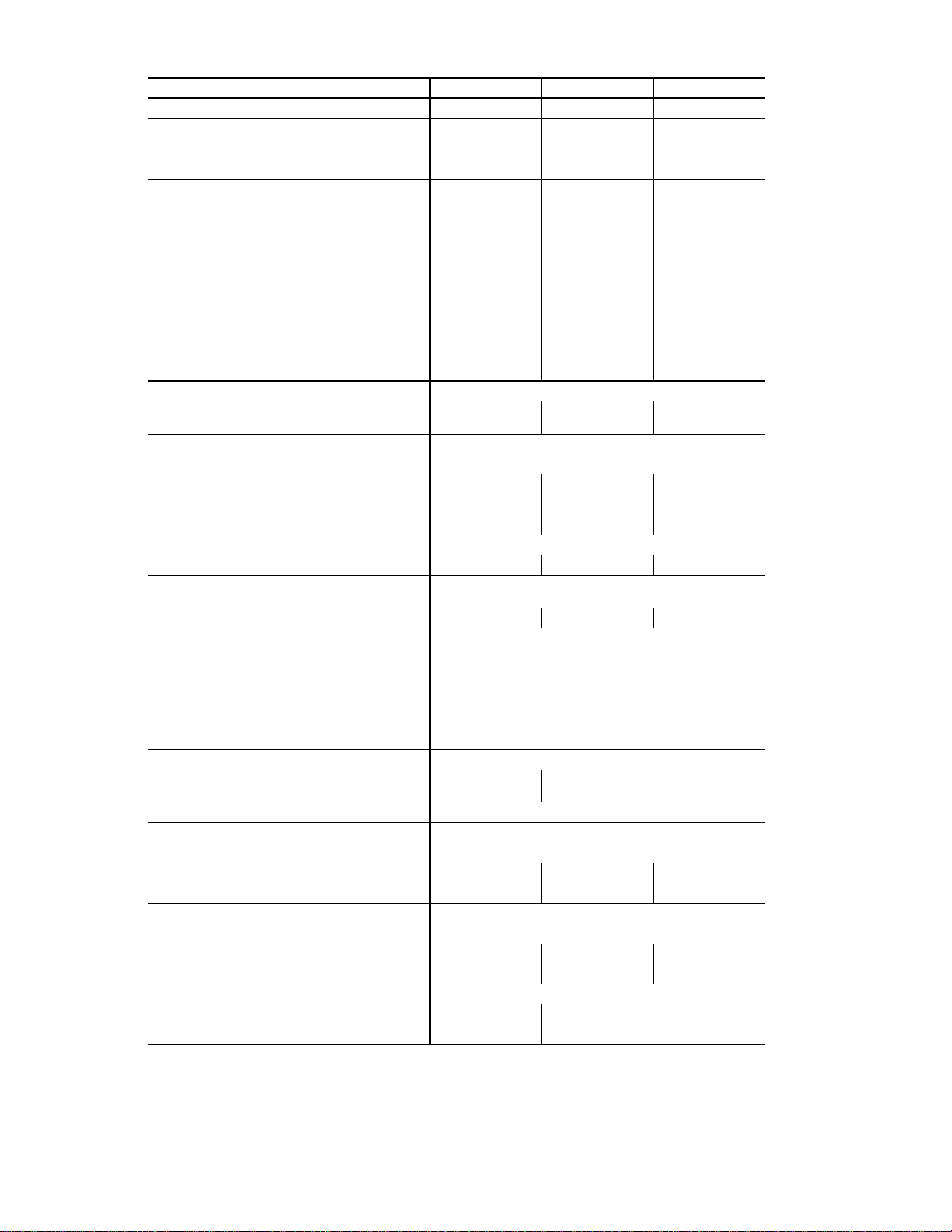
Table 1B — 40RUA Physical Data, SI — Cooling Units
UNIT 40RUA* 252830
NOMINAL CAPACITY (kW) 70 87 105
OPERATING WEIGHT (kg)
Base Unit with TXV 331 477 482
Plenum 102 148 148
FANS
Qty...Diam. (mm) 2...381 2...457 2...457
Nominal Airflow (L/s) 3775 4119 5663
Airflow Range (L/s) 2831 – 4719 3539 – 5899 4247 – 7079
Nominal Motor kW (Standard Motor)
208/230-3-60 and 460-3-60 3.73 5.60 7.46
575-3-60 3.73 5.60 7.46
Motor Speed (r/s)
208/230-3-60 and 460-3-60 29.1 29.1 29.1
575-3-60 29.1 29.3 29.3
REFRIGERANT R-410A
Operating charge (kg)
(approx per circuit)
DIRECT-EXPANSION COIL Enhanced Copper Tubes, Aluminum Sine-Wave Fins
Max Working Pressure (kPag) 3102
Face Area (sq m) 1.85 2.30 2.77
No. of Splits 222
No. of Circuits per Split 18 20 24
Split Type...Percentage Face...50/50
Fins/m 670 591 591
PIPING CONNECTIONS,
Quantity...Size (in.)
DX Coil — Suction (ODF) 2...1
DX Coil — Liquid Refrigerant (ODF) 2...5/
Steam Coil, In (MPT) 1...21/
Steam Coil, Out (MPT) 1...1/
Hot Water Coil, In (MPT) 1...2
Hot Water Coil, Out (MPT) 1...2
Condensate (PVC) 1...1
FILTERS Throwaway — Factory Supplied
Quantity...Size (mm.)
Access Location Either Side
STEAM COIL
‡
Max Working Pressure (kPag at 126°C) 138
Total Face Area (sq m) 1.24 1.39 1.39
Rows...Fins/m 1...394 1...394 1...394
HOT WATER COIL
Max Working Pressure (kPag) 1034
Total Face Area (sq m) 1.24 1.39 1.39
Rows...Fins/m 2...335 2...335 2...335
Water Volume
(L) 52.6 54.1
3
) 0.052 0.054
(m
LEGEND
DX — Direct Expansion
TXV — Thermostatic Expansion Valve
†
Units are shipped without refrigerant charge.
‡
Field installed accessory only.
†
‡
1.59 2.04 2.27
1
/
8
4...406 x 508 x 51
4...406 x 610 x 51
2...13/
8
8
2
2
1
/4 ODM/1 IDF
4...508 x 610 x 51
4...508 x 635 x 51
2...13/
8
6
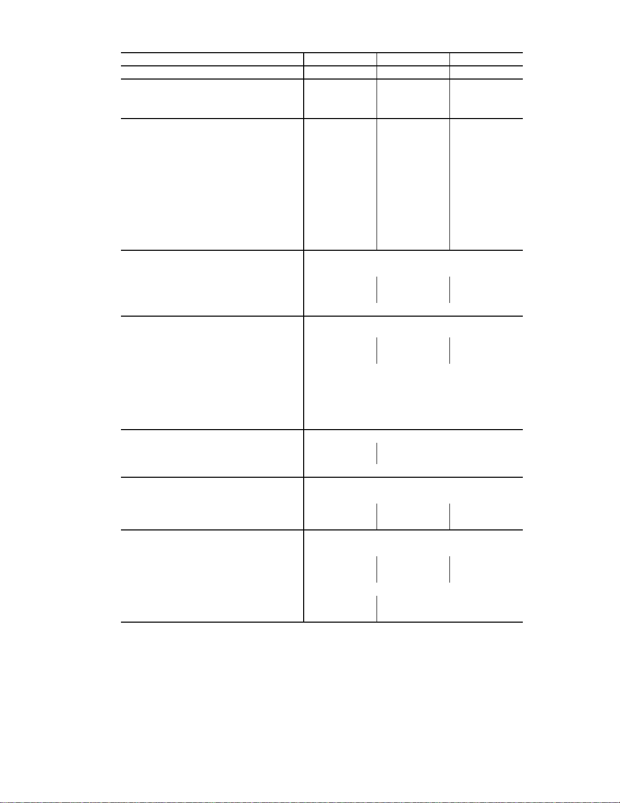
Table 1C — 40RUS Physical Data, English — Chilled Water Units
UNIT 40RUS* 252830
NOMINAL CAPACITY (Tons) 20 25 30
OPERATING WEIGHT (lb)
Base Unit 683 1035 1042
Plenum 225 325 325
FANS
Qty...Diam. (in.) 2...15 2...18 2...18
Nominal Airflow (cfm) 8,000 10,000 12,000
Airflow Range (cfm) 6,000 – 10,000 7,500 – 12,500 9,000 – 15,000
Nominal Motor Hp (Standard Motor)
208/230-3-60 and 460-3-60 5.0 7.5 10.0
575-3-60 5.0 7.5 10.0
Motor Speed (rpm)
208/230-3-60 and 460-3-60 1745 1745 1745
575-3-60 1745 1755 1755
CHILLED WATER COIL Enhanced Copper Tubes, Aluminum Sine-Wave Fins
Max Working Pressure (psig) 435
Face Area (sq ft) – Upper 11.0 12.4 15.5
Face Area (sq ft) – Lower 8.3 12.4 12.4
Rows...Fins/in. 3...15
PIPING CONNECTIONS,
Quantity...Size (in.)
3
Chilled Water — In 2...1
Chilled Water — Out 2...1
Steam Coil, In (MPT) 1...2
Steam Coil, Out (MPT) 1...11/
Hot Water Coil, In (MPT) 1...2
Hot Water Coil, Out (MPT) 1...2
Condensate (PVC) 1...1
FILTERS Throwaway — Factory Supplied
Quantity...Size (in.)
Access Location Either Side
STEAM COIL
‡
Max Working Pressure (psig at 260°F) 20
Total Face Area (sq ft) 13.33 15.0 15.0
Rows...Fins/in. 1...10 1...10 1...10
HOT WATER COIL
‡
Max Working Pressure (psig) 150
Total Face Area (sq ft) 13.33 15.0 15.0
Rows...Fins/in. 2...8.5 2...12.5 2...12.5
Water Volume
(gal) 13.9 14.3
3
) 1.1 1.90
(ft
LEGEND
‡
Field installed accessory only.
/8 ODM 2...21/8 ODM 2...21/8 ODM
3
/8 ODM 2...21/8 ODM 2...21/8 ODM
1
/
2
2
1
/4 ODM/1 IDF
4...16 x 20 x 2
4...16 x 24 x 2
4...20 x 24 x 2
4...20 x 25 x 2
7
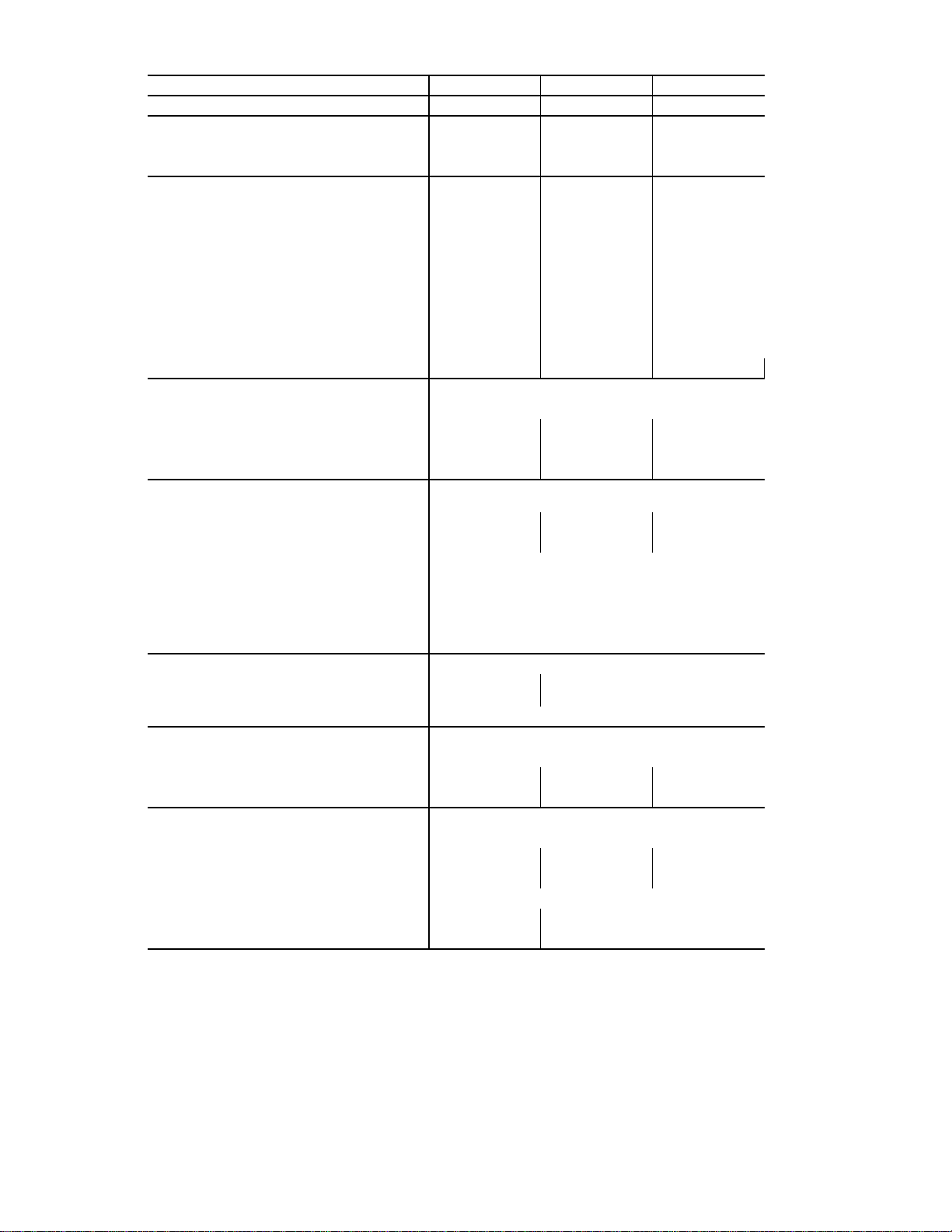
Table 1D — 40RUS Physical Data, SI — Chilled Water Units
UNIT 40RUS* 252830
NOMINAL CAPACITY (kW) 70 87 105
OPERATING WEIGHT (kg)
Base Unit 310 469 473
Plenum 102 148 148
FANS
Qty...Diam. (mm) 2...381 2...457 2...457
Nominal Airflow (L/s) 3775 4719 5663
Airflow Range (L/s) 2831 – 4719 3539 – 5899 4247 – 7079
Nominal Motor kW (Standard Motor)
208/230-3-60 and 460-3-60 3.73 5.60 7.46
575-3-60 3.73 5.60 7.46
Motor Speed (r/s)
208/230-3-60 and 460-3-60 29.1 29.1 29.1
575-3-60 29.1 29.3 29.3
CHILLED WATER COIL Enhanced Copper Tubes, Aluminum Sine-Wave Fins
Max Working Pressure (kPag) 2999
Face Area (sq m) – Upper 1.02 1.15 1.44
Face Area (sq m) – Lower 0.77 1.15 1.15
Rows...Fins/m 3...591 3...591 3...591
PIPING CONNECTIONS,
Quantity...Size (in.)
3
Chilled Water — In 2...1
Chilled Water — Out 2...1
Steam Coil, In (MPT) 1...2
Steam Coil, Out (MPT) 1...11/
Hot Water Coil, In (MPT) 1...2
Hot Water Coil, Out (MPT) 1...2
Condensate (PVC) 1...1
FILTERS Throwaway — Factory Supplied
Quantity...Size (mm.)
Access Location Either Side
STEAM COIL
‡
Max Working Pressure (kPag at 125°C) 138
Total Face Area (sq m) 1.24 1.39 1.39
Rows...Fins/m 1...394 1...394 1...394
HOT WATER COIL
‡
Max Working Pressure (kPag) 1034
Total Face Area (sq m) 1.24 1.39 1.39
Rows...Fins/m 2...335 2..493 2...493
Water Volume
(L) 52.6 54.1
3
) 0.052 0.054
(m
LEGEND
‡
Field installed accessory only.
/8 ODM 2...21/8 ODM 2...21/8 ODM
3
/8 ODM 2...21/8 ODM 2...21/8 ODM
1
/
2
2
1
/4 ODM/1 IDF
4...406 x 508 x 51
4...406 x 610 x 51
4...508 x 610 x 51
4...508 x 635 x 51
8
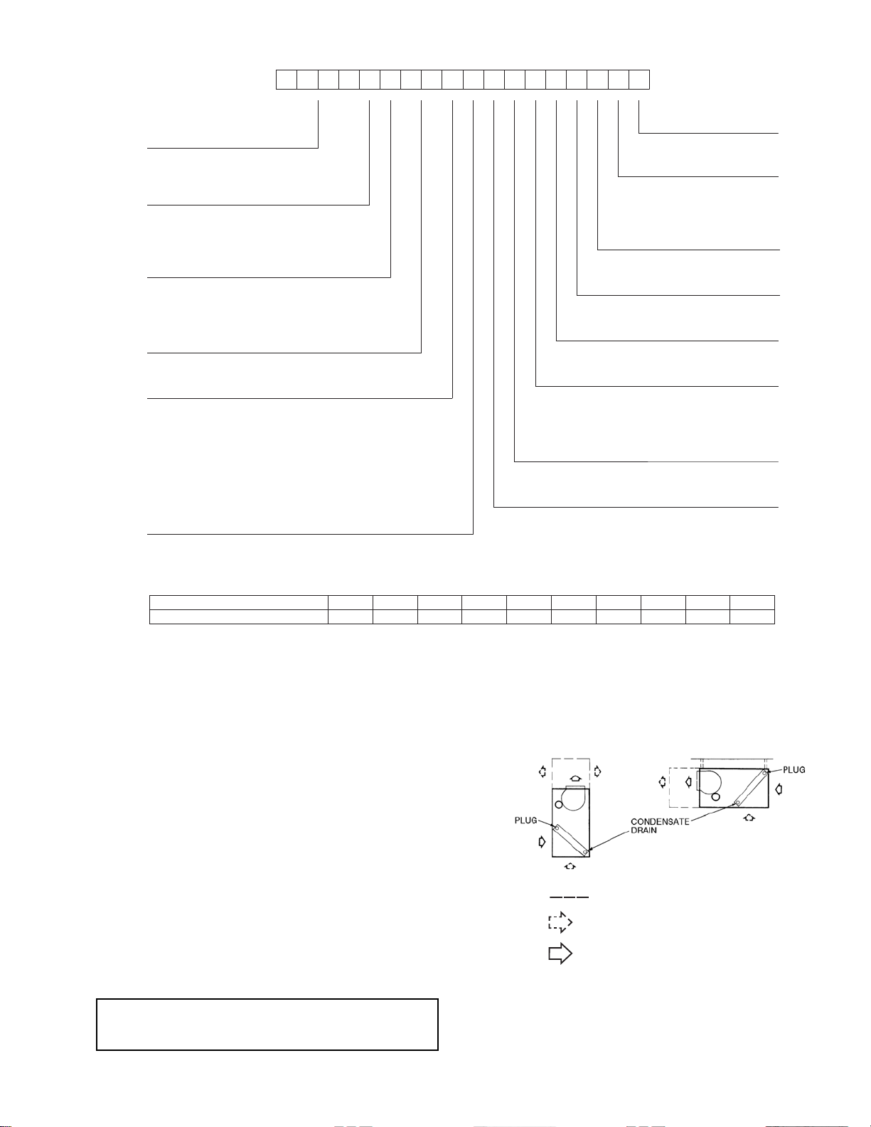
Fig. 3 — Model Number Nomenclature
1 2 3 4 5 6 7 8 9 10 11 12 13 14 15 16 17 18
4 0 R U A A 2 5 A 1 A 6 – 0 A 0 A 0
_____________ ____
Model Type Brand / Packaging
40RU = Carrier Fan Coil
Puronr R---410A Refrigerant
0=Standard
Typ e of C oil
Not Used
A=StandardDXCoil
A=PlaceHolder
S = Chilled Water Coil
Refrigerant Options
Service Options
C = Hot Water Coil
A=None
B = Steam Coil
0 = Non-Painted Cabinet
1=PaintedCabinet
Nominal Tonnage
25 = 20 Tons
28 = 25 Tons
Not Used
30 = 30 Tons
A=PlaceHolder
Not Used
0=PlaceHolder
Not Used
A=PlaceHolder
Design Rev
--- = Catalog Model Number
Indoor Fan Options
1 = Fan Drive and Motor - Low / Motor Efficiency - Standard
Voltage
2 = Fan Drive and Motor - Med / Motor Efficiency - Standard
1 = 575/3/60
3 = Fan Drive and Motor - High / Motor Efficiency - Standard
4 = Fan Drive and Motor - Low / Motor Efficiency - Premium
5 = Fan Drive and Motor - Med / Motor Efficiency - Premium
5 = 208/ 230/3/60
6 = 460/3/60
6 = Fan Drive and Motor - High / Motor Efficiency - Premium
Coil Options
A=Al/Cu
SETANGISEDNOITISOP
)radnelac lacsif( erutcafunam fo keeW1−2
)ASU ,saxeT ,PTE = G( noitacol gnirutcafunaM5
rebmun laitneuqeS6−10
12345678910
4808G12345
POSITION NUMBER
TYPICAL
Year of manufacture (”08” = 2008)3−4
LEGEND
Accessory Line
Alternate Air Intake and Discharge
Air Intake and Discharge
Note:
Maintain recommended clearances
per Figs. 2A–2B
Unit Positioning — The unit can be mounted on the
floor for vertical application with return air entering the face of
the unit and supply air discharging vertically through the top of
the unit. The unit can also be applied in a horizontal
arrangement with return air entering horizontally and the
supply air discharging horizontally. When applying the unit in
a horizontal arrangement, ensure the condensate drain pan is
located at the bottom center of the unit for adequate condensate
disposal. See Fig. 5 for condensate connections for each unit
position.
T ypical positioning and alternate return air locations are shown
in Fig. 5. Alternate return air locations can be used by moving
the unit panel from the alternate return air location to the
standard return air location. Refer to overhead suspension
accessory drawing (Fig. 6) for preferred suspension technique.
The unit needs support underneath to prevent sagging.
IMPORTANT: Do NOT attempt to install unit with return
air entering top panel of unit. Condensate will not drain
from unit.
Fig. 4 — Serial Number Nomenclature
9
Fig. 5 — Typical Unit Positioning
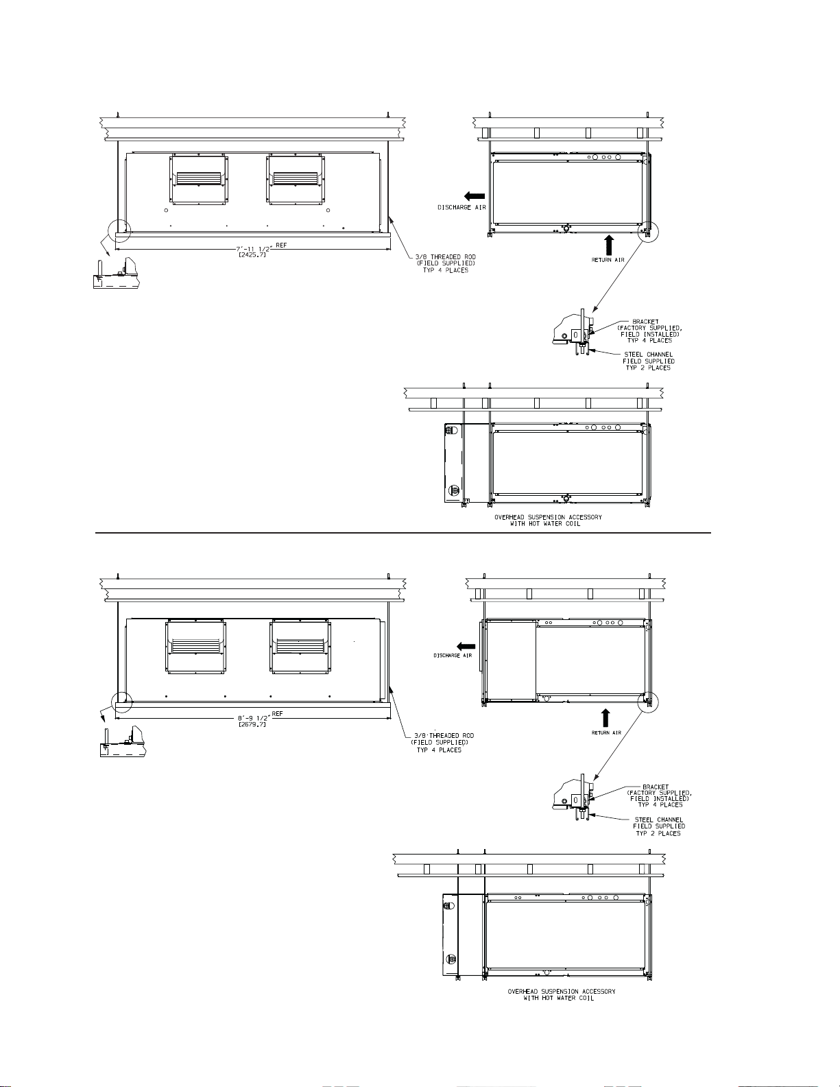
OVERHEAD SUSPENSION ACCESSORY
UNIT SIZE 25
UNIT SIZES 28, 30
NOTE: Dimensions in [ ] are millimeters
Fig. 6 — Preferred Suspension Technique
10
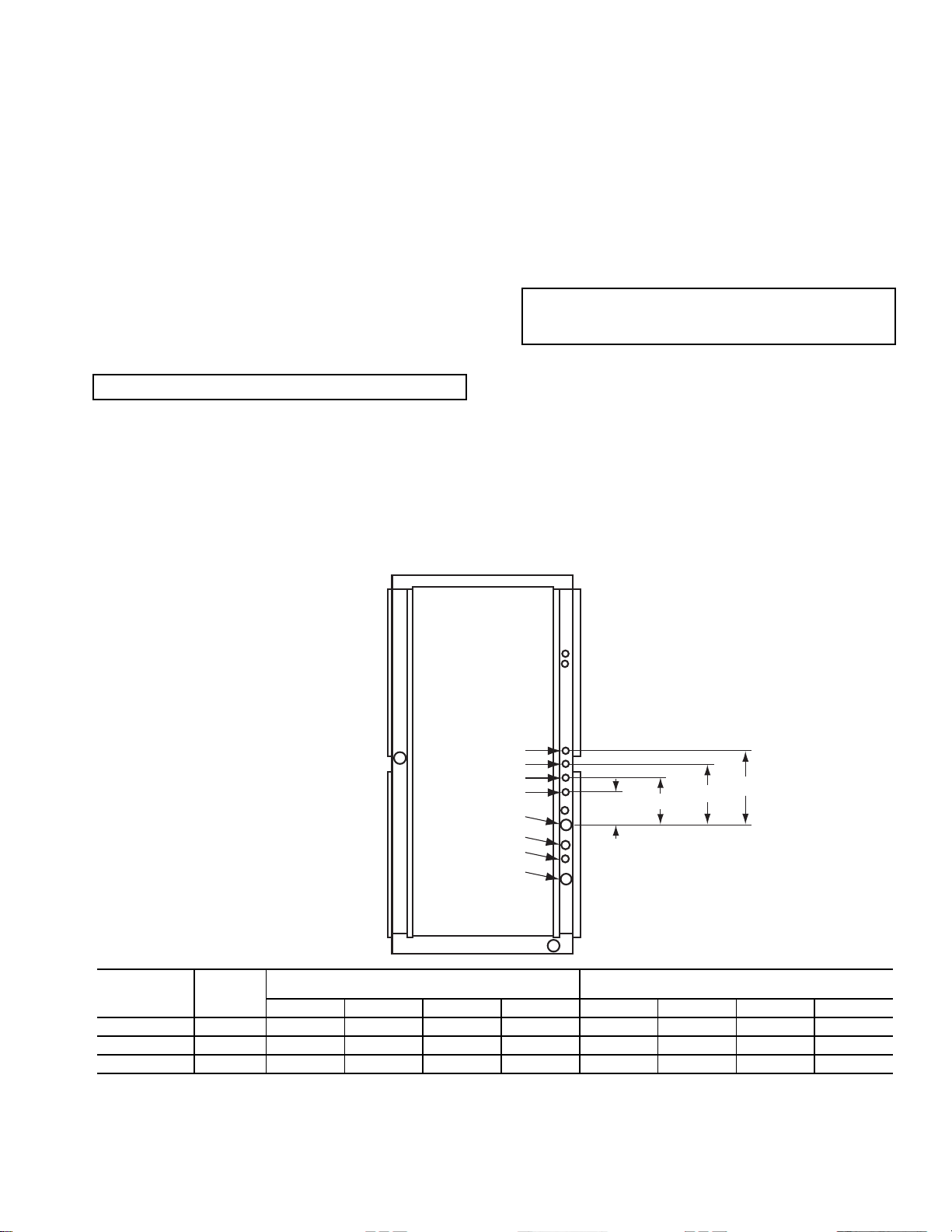
Unit Isolation — Where extremely quiet operation is
UNIT
USE HOLE
NUMBERS
FIELD-FABRICATED HOLE DIAMETERS
in. (mm)
FIELD-FABRICATED HOLE POSITION
DIMENSIONS, in. (mm)
No. 5No. 6No. 7No.8ABCD
40RUA*25, 28, 30 1, 2, 3, 4————————
40RUS*25 4, 5, 6, 7 1
3
/4 (44.5) 13/4 (44.5) 13/4 (44.5) — 3.0 (76.2) 6.0 (152.5) 10.5 (266.7)
40RUS*28, 30 5, 6, 7, 8 2
1
/2 (63.5) 21/2 (63.5) 21/2 (63.5) 21/2 (63.5) 6.0 (152.5) 9.625 244.5) 13.38 (339.9) 17.0 (431.8)
essential, install isolators between floor and base of unit, or
between ceiling and top section of unit.
Be sure that unit is level and adequately supported. Use
channels at front and sides of unit for reference points when
leveling.
Refrigerant and Chilled Water Piping
Access —
knockouts for refrigerant and chilled water piping. These
knockouts are located on both sides of the unit for installation
flexibility. The standard knockouts provide sufficient access to
the unit’s coils for all 40RUA*25, 28, and 30 units. RUS*25,
28, and 30 units require additional holes which must be fieldfabracated to accomodiate the piping. See Fig. 7 for the
positions and dimensions of the additional access holes
required for the RUS units. Recommended access hole use is
also listed for all units. Note that Fig. 7 shows the access holes
on the control-box side of the unit; this is the side of the unit
with the coil headers, so it is used most often for piping access.
IMPORTANT : Do not bury refrigerant piping underground.
The 40RU Series units come with standard
Refrigerant Piping — See Tables 1A–1D for refrigerant
pipe connection sizes. For ease in brazing, it is recommended
that all internal solder joints be made before unit is placed in
final position.
The 40RU direct-expansion units have internal
factory-installed thermostatic expansion valves (TXVs),
distributors, and nozzles for use with R-410A. See Table 2
for part numbers. Knockouts are provided in the unit corner
posts for 40RU refrigerant piping. See Fig. 7, which also
lists recommended knockouts and access holes to use for
each 40RU unit size. Recommended fittings are listed in
Table 3.
The sensor bulb capillary tubes must be routed from the TXVs
inside the unit through one of the piping access holes. Clamp
the TXV sensor bulb on a vertical portion of the suction line,
outside the unit. See Fig. 8.
NOTE: Be sure to remove the styrofoam shipping pad from
the TXV. Verify that it has been removed. See Fig. 1.
IMPORTANT: Never attach the sensor to the suction
manifold. Do NOT mount the sensor on a trapped portion
of the suction line.
The 40RU Series evaporator coils have a face-split design.
Ensure that lower circuit of coil is first on/last off when
connected to the condensing unit and/or system controls. See
Fig. 9.
External TXV equalizer connections are provided and
factory-brazed into the coil suction manifolds.
If suction line must be horizontal, clamp bulb to suction line at
least 45 degrees above bottom, at approximately the 4 o’clock
or 8 o’clock position. See Fig.10.
8
7
6
5
4
3
2
1
Fig. 7 — Refrigerant and Chilled Water Piping Access Holes
11
B
A
D
C
 Loading...