


PremierLink™
Retrofit Split System
Controller
Installation, Start-Up and
Configuration Instructions
Part Number 33CSPREMLK
CONTENTS
Page
SAFETY CONSIDERATIONS . . . . . . . . . . . . . . . . . . . . . . 1
GENERAL . . . . . . . . . . . . . . . . . . . . . . . . . . . . . . . . . . . . . . .1,2
INSTALLATION . . . . . . . . . . . . . . . . . . . . . . . . . . . . . . . . 2-26
Inspection. . . . . . . . . . . . . . . . . . . . . . . . . . . . . . . . . . . . . . . . 2
PremierLink Controller Hardware. . . . . . . . . . . . . . . . . 2
Field-Supplied Hardware . . . . . . . . . . . . . . . . . . . . . . . . . 2
•SPACE TEMPERATURE (SPT) SENSOR
•SUPPLY AIR TEMPERATURE (SAT) SENSOR
•INDOOR AIR QUALITY CO2 SENSOR
•OUTDOOR AIR QUALITY CO2 SENSOR
•OUTDOOR AIR TEMPERATURE SENSOR
•OUTDOOR AIR ENTHALPY SWITCH
•RETURN AIR ENTHALPY SENSOR
Mount PremierLink Control. . . . . . . . . . . . . . . . . . . . . . . 2
•LOCATION
•MOUNTING
PremierLink Controller Inputs and Outputs . . . . . . 3
Control Wiring. . . . . . . . . . . . . . . . . . . . . . . . . . . . . . . . . . . . 3
Install Sensors . . . . . . . . . . . . . . . . . . . . . . . . . . . . . . . . . . . 9
•SPACE TEMPERATURE (SPT) SENSOR INSTALLATION
•SUPPLY AIR TEMPERATURE (SAT) SENSOR INSTALLATION
•INDOOR AIR QUALITY CO2 SENSOR INSTALLATION
•OUTDOOR AIR QUALITY CO2 SENSOR INSTALLATION
•OUTDOOR AIR TEMPERATURE SENSOR
Connect to CCN Communication Bus . . . . . . . . . . . 18
• COMMUNICATIONS BUS WIRE SPECIFICATIONS
Enthalpy and Differential Enthalpy Control . . . . . . 18
•ENTHALPY SWITCH/RECEIVER
•OUTDOOR AND RETURN AIR ENTHALPY SENSOR
Economizer . . . . . . . . . . . . . . . . . . . . . . . . . . . . . . . . . . . . . 21
•Q769B
•Q769C
Economizer with Johnson 4 to 20 mA
Actuator . . . . . . . . . . . . . . . . . . . . . . . . . . . . . . . . . . . . . . 24
•DRIVE DIRECTION
•SWITCH SELECTION
•WIRING
START-UP . . . . . . . . . . . . . . . . . . . . . . . . . . . . . . . . . . . . 26-28
Perform System Check-Out . . . . . . . . . . . . . . . . . . . . . 26
Initial Operation and Test. . . . . . . . . . . . . . . . . . . . . . . . 26
Install Navigator™ Display Module . . . . . . . . . . . . . 26
Password Protection . . . . . . . . . . . . . . . . . . . . . . . . . . . . 28
Forcing Values and Configuring Items . . . . . . . . . . 28
Page
CONFIGURATION . . . . . . . . . . . . . . . . . . . . . . . . . . . . 28-42
Points Display Screen. . . . . . . . . . . . . . . . . . . . . . . . . . . 28
Thermostat Control Input Screen. . . . . . . . . . . . . . . . 30
Alarm Service Configuration Screen . . . . . . . . . . . . 30
Controller Identification Screen . . . . . . . . . . . . . . . . . 31
Holiday Configuration Screen . . . . . . . . . . . . . . . . . . . 31
Occupancy Configuration Screen . . . . . . . . . . . . . . . 32
Set Point Screen . . . . . . . . . . . . . . . . . . . . . . . . . . . . . . . . 32
Service Configuration Selection Screen. . . . . . . . . 33
PremierLink Configuration Screen . . . . . . . . . . . . . . 37
Occupancy Maintenance Screen . . . . . . . . . . . . . . . . 39
Maintenance Screen . . . . . . . . . . . . . . . . . . . . . . . . . . . . 40
SAFETY CONSIDERATIONS
SAFETY NOTE
Air-handling equipment will provide safe and reliable service when operated within design specifications. The equipment should be operated and serviced only by authorized personnel who have a thorough knowledge of system operation, safety devices and emergency procedures.
Good judgement should be used in applying any manufacturer’s instructions to avoid injury to personnel or damage to equipment and property.
Disconnect all power to the unit before performing maintenance or service. Unit may automatically start if power is not disconnected. Electrical shock and personal injury could result.
Damage to equipment may result. An individual fieldsupplied 24-vac power transformer is required for each PremierLink controller. The transformer must be less than 100 va to meet UL (Underwriters’ Laboratories) Class 2.
GENERAL
The PremierLink Controller is a field retrofit split system control compatible with the Carrier Comfort Network (CCN). This control is designed to allow users the access and ability to change factory-defined settings thus expanding the function of the standard unit control board. The complete PremierLink package (part number 33CSPREMLK) consists of a control circuit board with plastic cover and label, wire harnesses, spade connectors, wire nuts and 4 mounting screws.
Manufacturer reserves the right to discontinue, or change at any time, specifications or designs without notice and without incurring obligations.
Book |
1 |
4 |
PC 111 |
Catalog No. 533-80072 |
Printed in U.S.A. |
Form 38-54SI |
Pg 1 |
11-02 |
Replaces: 38-52SI |
Tab |
3a |
2a |
|
|
|
|
|
|
|
|
|
|
|
|
|
|
|
|
|
IMPORTANT: PremierLink™ part number 33CSPREMLK should only be used in applications where the integrity of the Underwriters Laboratories rating will be maintained.
Carrier’s diagnostic standard tier display tools such as Navigator or Scrolling Marquee can be used with the PremierLink controller. Access is available via an RJ-11 connection or a 3-wire connection to the communication bus. User interfaces available for use with the CCN system are PC’s equipped with Carrier user interface software such as Service Tool, ComfortVIEW™, or ComfortWORKS® software. When used as part of the CCN, other devices such as the CCN data transfer, Linkage Thermostat, or Comfort Controller can read data from or write data to the PremierLink retrofit controller.
INSTALLATION
Inspection — Inspect package contents for visual defects that may have occurred during shipping. If there is any damage, contact your local representative before proceeding.
PremierLink Controller Hardware — The PremierLink package consists of the following hardware:
•control module (with plastic cover and label)
•7 wire harnesses
•10 spade connectors
•wire nuts
•4 no. 6x1-in. self-drilling Phillips pan head mounting screws
Field-Supplied Hardware — PremierLink controller is configurable with the following field-supplied sensors:
•space temperature sensor (33ZCT55SPT, 33ZCT56SPT, or 33ZCT58SPT) in sensor mode or thermostat mode for economizer control
•supply air temperature sensor (33ZCSENSAT) required for all applications
•indoor air quality sensor (33ZCSENCO2, 33ZCT55CO2, 33ZCT56CO2) required only for demand control ventilation
•outdoor air quality sensor (33ZCTSENCO2) required only for demand control ventilation
•outdoor air temperature sensor (HH79NZ017)
•outdoor air enthalpy switch (33CSENTHSW)
•return air enthalpy sensor (33CSENTSEN)
For specific details about sensors, refer to the literature supplied with the sensor.
SPACE TEMPERATURE (SPT) SENSOR — A field-supplied Carrier space temperature sensor is required to maintain space temperature in sensor mode. There are three sensors available for this application:
•33ZCT55SPT, Space Temperature Sensor with Override Button
•33ZCT56SPT, Space Temperature Sensor with Override Button and Set Point Adjustment
•33ZCT58SPT, T58 Communicating Room Sensor with Override Button, Set Point Adjustment, and Manual Fan control
If controlling an economizer in the thermostat mode, a duct sensor must be mounted in the return air duct and wired to SPT input.
SUPPLY AIR TEMPERATURE (SAT) SENSOR — The PremierLink controller must be connected to a field-supplied supply air temperature (SAT) sensor (part number 33ZCSENSAT) to monitor the temperature of the air delivered.
The SAT consists of a thermistor encased within a stainless steel probe. The probe is 6 in. nominal length. The SAT sensor has 114 in. of unshielded, plenum-rated cable (2 conductors, 22 AWG [American Wire Gage]). The sensor range is –40 to 185 F with a nominal resistance of 10,000 ohms at 77 F. The sensor measures temperature with an accuracy of ±0.36 F.
Ideally, the SAT sensor should be located in the supply air duct downstream from unit heat source to control.
INDOOR AIR QUALITY CO2 SENSOR — An indoor air quality sensor is required for CO2 level monitoring. Three different CO2 sensors are available for this application:
•33ZCSENCO2 sensor is an indoor, wall-mounted sensor with an LED (light-emitting diode) display
•33ZCT55CO2 sensor is an indoor, wall-mounted sensor
without display. The CO2 sensor also includes a space temperature sensor with override button
•33ZCT56CO2 sensor is an indoor, wall-mounted sensor
without display. The CO2 sensor also includes a space temperature sensor with override button and temperature offset
OUTDOOR AIR QUALITY CO2 SENSOR — The outdoor air CO2 sensor (33ZCTSENCO2) is designed to monitor carbon dioxide (CO2) levels found in diesel exhaust and control ventilation systems. It comes with an outdoor enclosure. This sensor provides an outdoor baseline for differential DCV (Demand Control Ventilation) control.
OUTDOOR AIR TEMPERATURE SENSOR — The outdoor air temperature sensor (HH79NZ017) monitors the temperature outside of the outside air entering the equipment.
OUTDOOR AIR ENTHALPY SWITCH — The outdoor air enthalpy switch (33CSENTHSW) monitors outdoor air enthalpy and dry bulb temperature to determine when free cooling can be used.
RETURN AIR ENTHLAPY SENSOR — The return air enthalpy sensor (33CSENTSEN), when used in conjunction with the outdoor air enthalpy switch, compares the outdoor air and return air to determine when free cooling can be used.
Mount PremierLink Control
LOCATION — The PremierLink controller should be located inside one of the available service access panels of the indoor unit. Be sure the location selected prevents moisture and rain from coming into contact with the circuit board.
Select a location which will be safe from water damage and allow sufficient access for service and wiring. For service access, there should be at least 6 in. of clearance between the front of the PremierLink controller and adjacent surfaces. Be sure to leave 1/2-in. clearance in front of RJ-14 connector for attaching RJ-14 cable from CCN or Navigator™ display module. A field-supplied right angle 6-pin RJ-14 connector can be attached if necessary.
NOTE: If the PremierLink controller must be installed in a location where there is not easy access to CCN connectors, a remote connection kit (part number 33CSREMCCN) can be ordered.
MOUNTING — Refer to Mounting Sheet included with controller for additional detailed mounting instructions.
1.Ensure all power to unit is removed.
2.Locate a space in the unit control panel or a space inside the equipment that is free from dirt and dust.
3.Remove plastic cover by gently squeezing the middle of longer sides of the cover and pull away from the board. This will release the locking tabs inside.
4.Mount the PremierLink controller to the desired location by holding the controller firmly in place. Be sure all standoffs are in contact with mounting surface and board DOES NOT flex! Attach controller to unit using 4 screws provided ensuring a secure grip to unit surface. See Fig. 1.
5.Provide 24 v power to the circuit board from the unit transformer or an isolated power transformer. Use the appropriate conductors for voltage per base unit nameplate. See Fig. 2A-2I. Board will require 10 va at 24 vac.
6.Replace plastic cover to protect circuit board.
7.Restore power to unit.
2

*To restore factory default settings, the unit must be in the unpowered state. Move Switch 4 to Position 1 and then restore unit power.
Fig. 1 — PremierLink™ Control Module
PremierLink Controller Inputs and Outputs —
The PremierLink controller inputs and outputs are shown in Table 1.
Disconnect electrical power before wiring the PremierLink controller. Electrical shock, personal injury, or damage to the PremierLink controller can result.
Control Wiring — The PremierLink controller can be connected to either a Carrier-approved thermostat or CCN compatible temperature sensor.
1.Turn off power to the control box.
2.Strip the ends of the red, white, and black conductors of the communication bus cable.
NOTE: When connecting the communication bus cable, a color code system for the entire network is recommended to simplify installation and checkout. See Table 2 for the recommended color code.
3.Use 4-connector Molex with red, white and black wires to connect the communication wires. Verify the color codes in Table 2 to ensure the Red (+) wire connects to Terminal 1. Connect the White (ground) wire to Terminal 2. Connect the Black (–) wire to Terminal 3.
4.Secure all connections in Step 3 with wire nuts.
5.Insert the plug into the existing 4-pin mating connector on the base module in the main control box (Terminal J-2).
6.Restore power.
3
PremierLink Connections
|
|
|
|
PWR |
RED |
|
|
|
|
|
|
|
|
|
|
HS3/EXH/RVS |
ORN |
|
|
|
|
|
|
|
|
RED |
|
|
|
|
|
|
|
HS2 |
PNK |
DUALFORCUT |
TRANSFORMER EQUIPTMENT |
RELAYS |
|
|
|
|
|
|
|||
|
|
RED |
|
|
|
|
|
|
|
HS1 |
WHT |
|
|
|
|
|
|
|
|
|
|
CMP2 |
BLU |
|
|
|
|
|
|
|
|
RED |
|
CMP1 |
|
|
|
|
|
YEL |
|
CUTTO ISOLATE |
CONTROLLER POWER |
PWR |
|
|
|
J1 |
|
|
|||
|
|
RED |
|
|
|
|
|
|
J8 |
FAN |
GRN |
|
|
|
|
|
|
BRN
|
40RM Connections |
38AK, AKS, ARZ, ARS |
||
|
|
|
Terminal |
|
|
|
|
Board (TB) |
|
R |
|
|
|
|
Y1 |
40RM, 40RMQ, 40RMS |
|
||
Y2 |
|
HEAT ACCESSORY |
|
|
|
|
|
||
W1 |
|
W1 |
R |
|
|
|
|||
W2 |
|
W2 |
Y1 |
|
G |
WHT C1 IFC C2 |
C |
||
|
||||
C |
WHT |
|
Y2 |
|
X |
|
|
W1 |
|
|
CCR |
|
||
|
|
|
||
|
|
|
W2 |
|
|
|
LLSV |
G |
|
|
|
|
C |
|
|
|
|
X |
|
|
|
CCSV |
|
|
CCR
LEGEND
CCR — Capacity Control Relay (If Equipped)
CCSV — Capacity Control Valve, Indoor Coil (If Equipped)
IFC — Indoor-Fan Contactor
LLSV — Liquid Line Solenoid Valve
NOTE: Configure AC to “0”.
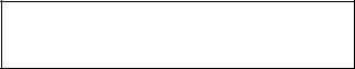
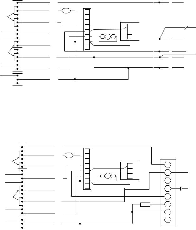
Fig. 2A — Typical PremierLink™ Control Wiring — 38AK,AKS,ARZ,ARS007-012 Units
PremierLink Connections
|
|
|
|
PWR |
RED |
|
|
|
|
|
|
|
|
|
|
HS3/EXH/RVS |
ORN |
|
|
|
|
|
|
|
|
RED |
|
|
|
|
|
|
|
HS2 |
PNK |
DUALFORCUT |
TRANSFORMER EQUIPTMENT |
RELAYS |
|
|
|
|
|
|
|||
|
|
RED |
|
|
|
|
|
|
|
HS1 |
WHT |
|
|
|
|
|
|
|
|
|
|
CMP2 |
BLU |
|
|
|
|
|
|
|
|
RED |
|
CMP1 |
|
|
|
|
|
YEL |
|
CUTTO ISOLATE |
CONTROLLER POWER |
PWR |
|
|
|
J1 |
|
|
|||
|
|
RED |
|
|
|
|
|
|
J8 |
FAN |
GRN |
|
|
|
|
|
|
BRN
|
40RM Connections |
|
38AKS |
|
|
|
Terminal |
|
|
|
Board (TB2) |
R |
|
|
|
Y1 |
40RM, 40RMQ, 40RMS |
|
|
Y2 |
HEAT ACCESSORY |
|
|
|
|
|
|
W1 |
|
W1 |
10 |
|
|
||
W2 |
|
W2 |
9 |
|
WHT C1 IFC C2 |
|
|
G |
C |
|
|
C |
WHT |
|
8 |
X |
|
|
|
|
CCR |
|
4 |
|
CR2 |
|
3 |
|
|
|
|
|
|
|
2 |
|
|
|
1 |
|
|
CCSV |
|
|
LEGEND |
|
CCR |
||
CCR |
— Capacity Control Relay (If Equipped) |
|
|
|
|
LLSV |
|
|
|
||
CCSV — Capacity Control Valve, Indoor Coil (If Equipped) |
|
|
|
|
|
|
CR2 |
||||
CR2 |
— Control Relay No. 2 (Liquid Line Solenoid Valve) |
|
|||
|
|
|
|
||
IFC |
— Indoor-Fan Contactor |
|
|
|
|
LLSV |
— Liquid Line Solenoid Valve |
|
|
|
|
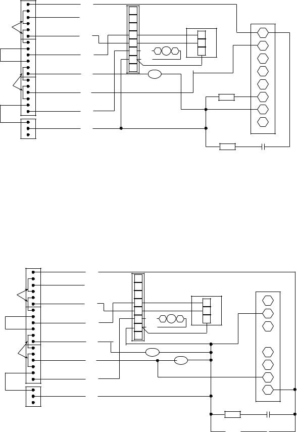
Fig. 2B — Typical PremierLink Control Wiring — 38AKS013-024 Units
4
|
|
PremierLink Connections |
|
|
40RM Connections |
||
|
|
|
PWR |
RED |
|
|
|
|
|
|
|
|
|
|
|
|
|
|
HS3/EXH/RVS |
|
R |
|
|
|
|
|
ORN |
Y1 |
|
|
|
|
|
|
|
40RM, 40RMQ, 40RMS |
|||
|
|
|
|
|
|||
|
|
RED |
|
|
Y2 |
|
HEAT ACCESSORY |
|
|
|
|
|
|
||
|
|
|
HS2 |
PNK |
W1 |
|
W1 |
DUALFORCUT |
TRANSFORMER EQUIPTMENT |
RELAYS |
|
|
|||
|
|
W2 |
|
W2 |
|||
|
|
RED |
|
|
|||
|
|
|
G |
WHT C1 IFC C2 |
C |
||
|
|
|
HS1 |
WHT |
|||
|
|
|
|
C |
WHT |
|
|
|
|
|
|
|
|
||
|
|
|
CMP2 |
|
X |
|
|
|
|
|
BLU |
|
CCR |
|
|
|
|
|
|
|
|
||
|
|
RED |
CMP1 |
|
|
|
|
|
|
|
YEL |
|
|
|
|
|
|
|
|
|
|
LLSV |
|
TOCUT ISOLATE |
CONTROLLER POWER |
PWR |
J1 |
|
|
|
|
|
|
RED |
|
|
|
|
|
|
|
|
FAN |
GRN |
|
|
|
|
|
|
J8 |
|
|
|
|
|
|
|
|
|
|
|
|
BRN
CCSV
LEGEND
CCR — Capacity Control Relay (If Equipped)
CCSV — Capacity Control Valve, Indoor Coil (If Equipped)
IFC — Indoor-Fan Contactor
LLSV — Liquid Line Solenoid Valve
NOTE: Configure AC to “0”.
Fig. 2C — Typical PremierLink™ Control Wiring — 38ARD012 Units
|
|
PremierLink Connections |
|
|
40RM Connections |
||
|
|
|
PWR |
RED |
|
|
|
|
|
|
|
|
|
|
|
|
|
|
HS3/EXH/RVS |
|
R |
|
|
|
|
|
ORN |
Y1 |
|
|
|
|
|
|
|
40RM, 40RMQ, 40RMS |
|||
|
|
|
|
|
|||
|
|
RED |
|
|
Y2 |
|
HEAT ACCESSORY |
|
|
|
|
|
|
||
|
|
|
HS2 |
PNK |
W1 |
|
W1 |
DUALFORCUT |
TRANSFORMER EQUIPTMENT |
RELAYS |
|
|
|||
|
|
W2 |
|
W2 |
|||
|
|
RED |
|
|
|||
|
|
|
G |
WHT C1 IFC C2 |
C |
||
|
|
|
HS1 |
WHT |
|||
|
|
|
|
C |
WHT |
|
|
|
|
|
|
|
|
||
|
|
|
CMP2 |
|
X |
|
|
|
|
|
BLU |
|
CCR |
|
|
|
|
|
|
|
|
||
|
|
RED |
CMP1 |
|
|
|
|
|
|
|
YEL |
|
|
|
|
CUTTO ISOLATE |
CONTROLLER POWER |
PWR |
|
|
|
|
|
J1 |
|
|
|
|
|||
|
|
RED |
|
|
|
|
|
|
|
|
FAN |
GRN |
|
|
|
|
|
|
J8 |
|
|
|
|
BRN
CCSV
LEGEND
CCR — Capacity Control Relay (If Equipped)
CCSV — Capacity Control Valve, Indoor Coil (If Equipped)
IFC — Indoor-Fan Contactor
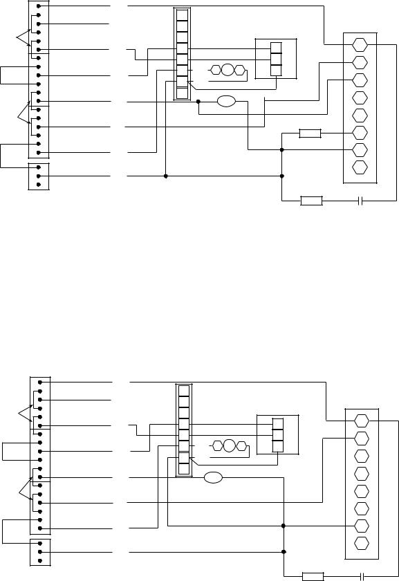
Fig. 2D — Typical PremierLink Control Wiring — 38AKS028-044 Units
38ARD Terminal Board (TB)
R
Y1
Y2
W1
W2
G
C
X
CCR
38AKS Terminal Board (TB3)
R
Y1
Y2
W1
W2
G
C
X
CCR
5
PremierLink Connections
|
|
|
|
PWR |
RED |
|
|
|
|
|
|
|
|
|
|
HS3/EXH/RVS |
ORN |
|
|
|
|
|
|
|
|
RED |
|
|
|
|
|
|
|
HS2 |
PNK |
DUALFORCUT |
TRANSFORMER EQUIPTMENT |
RELAYS |
|
|
|
|
|
|
|||
|
|
RED |
|
|
|
|
|
|
|
HS1 |
WHT |
|
|
|
|
|
|
|
|
|
|
CMP2 |
BLU |
|
|
|
|
|
|
|
|
RED |
|
CMP1 |
|
|
|
|
|
YEL |
|
CUTTO ISOLATE |
CONTROLLER POWER |
PWR |
|
|
|
J1 |
|
|
|||
|
|
RED |
|
|
|
|
|
|
J8 |
FAN |
GRN |
|
|
|
|
|
|
BRN
LEGEND
IFC — Indoor-Fan Contactor
|
40RM Connections |
38AH |
|
|
Terminal |
|
|
Board (TB2) |
R |
|
|
Y1 |
40RM, 40RMQ, 40RMS |
|
Y2 |
HEAT ACCESSORY |
|
|
|
|
W1 |
|
W1 |
W2 |
|
W2 |
G |
WHT C1 IFC C2 |
C |
C |
WHT |
5 |
X |
|
|
|
|
4 |
|
|
3 |
|
|
2 |
|
|
1 |
Fig. 2E — Typical PremierLink™ Control Wiring — 38AH024-034 Units
PremierLink Connections |
38AH Connections |
CUT FOR DUAL
ISOLATE
CUT TO
CR IFC IFR LLS TB
|
|
|
|
TB3 |
|
|
|
|
|
|
|
|
TB4 |
|
|
|
|
|
|
|
|
|
|
|
1 |
|
2 |
3 |
4 |
5 |
6 |
7 |
8 |
1 |
2 |
3 |
4 |
5 |
6 |
7 |
8 |
|
|
|
PWR |
RED |
ACCESSORY |
|
|
IFC |
|
|
|
|
|
|
|
|
|
|
|
|
|
|
|
|
RELAY |
|
|
|
|
|
|
|
|
|
LLS |
|
|
|
|||
|
|
|
|
|
PACKAGE |
|
|
|
|
|
|
|
|
|
|
|
|
|
||
|
|
|
HS3/EXH/RVS |
ORN |
|
CR1 |
|
|
|
LLS |
|
|
|
|
|
|
-B1 |
|
|
|
|
|
|
|
|
|
|
|
|
|
|
|
|
|
|
|
|
|
|||
|
|
|
|
|
|
VIO |
|
|
|
-A1 |
|
|
|
|
|
|
|
|
|
|
|
RED |
|
|
|
|
CR2 |
|
|
|
|
|
|
|
|
|
|
|
|
|
|
|
|
|
|
|
BRN |
|
|
|
|
|
|
|
|
|
|
|
|
|
|
|
|
|
|
HS2 |
|
|
|
|
|
|
|
|
|
|
|
|
|
|
|
|
|
|
|
|
PNK |
|
IFR |
|
|
|
|
|
|
|
|
|
|
|
|
|
|
|
TRANSFORMER EQUIPTMENT |
|
|
|
|
RED |
|
|
|
|
|
|
|
|
|
|
|
|
|
|
|
RELAYS |
|
|
|
4 |
|
|
|
|
|
|
|
|
|
|
|
|
|
|
||
|
|
|
CR2 |
|
|
|
|
|
|
|
|
|
|
|
|
|
|
|||
|
RED |
|
|
1 |
YEL |
|
|
|
|
|
|
|
|
|
|
|
|
|
||
|
|
|
HS1 |
|
|
24V |
|
|
|
|
|
|
|
|
|
|
|
|
|
|
|
|
|
|
WHT |
2 |
IFR |
|
|
|
|
|
|
|
|
|
|
|
|
|
|
|
|
|
|
|
|
|
|
|
|
|
|
|
|
|
|
|
|
|
||
|
|
|
CMP2 |
|
3 |
CR1 |
|
|
|
|
|
|
|
|
|
|
|
|
|
|
|
|
|
BLU |
|
|
|
|
|
|
|
|
|
|
|
|
|
|
|
|
|
|
|
|
|
|
|
|
|
|
|
|
|
|
|
|
|
|
|
|
|
|
|
RED |
|
CMP1 |
|
5 |
|
|
|
|
|
|
|
|
|
|
|
|
|
|
|
|
|
|
YEL |
|
|
|
|
|
|
|
|
|
|
|
|
|
|
|
||
CONTROLLER POWER |
PWR |
|
|
|
|
|
|
|
|
|
|
|
|
|
|
|
|
|
|
|
J1 |
|
|
|
|
|
|
|
|
|
|
|
|
|
|
|
|
|
|
||
|
RED |
|
|
|
|
|
|
|
|
|
|
|
|
|
|
|
|
|
|
|
|
|
J8 |
FAN |
GRN |
|
|
|
|
|
|
|
|
|
|
|
|
|
|
|
|
|
|
|
|
|
|
|
|
|
|
|
|
|
|
|
|
|
|
|
|
|
BRN
LEGEND
—Control Relay
—Indoor-Fan Contactor
—Indoor-Fan Relay
—Liquid Line Solenoid
—Terminal Block
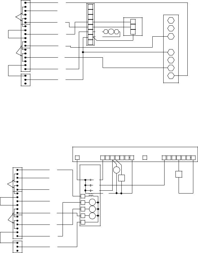
Fig. 2F — Typical PremierLink Control Wiring — 38AH004-104 Units
6
PremierLink Connections |
40RMQ Connections |
38AQ007 |
|
|
Control |
|
|
Connections |
|
|
|
|
PWR |
RED |
|
|
|
|
|
|
|
|
|
|
|
|
|
|
|
|
HS3/EXH/RVS |
ORN |
CR |
R |
|
|
|
|
|
|
|
|||
|
|
RED |
|
|
|
|
Y1 |
|
|
|
|
|
HS2 |
PNK |
|
Y2 |
|
DUALFORCUT |
TRANSFORMER EQUIPTMENT |
RELAYS |
|
|
|
|
||
|
|
|
|
W1 |
|
|||
|
|
RED |
|
|
|
|
||
|
|
|
|
|
|
|
||
|
|
|
|
HS1 |
WHT |
|
W2 |
|
|
|
|
|
|
|
G |
WHT |
|
|
|
|
|
|
|
|
||
|
|
|
|
CMP2 |
|
|
C |
WHT |
|
|
|
|
BLU |
|
|
|
|
|
|
|
|
|
|
X |
|
|
|
|
|
|
|
|
|
|
|
|
|
RED |
|
CMP1 |
|
|
|
|
|
|
|
|
YEL |
|
|
|
|
CUTTO ISOLATE |
CONTROLLER POWER |
PWR |
|
|
|
|
|
|
J1 |
|
|
|
|
|
|||
|
|
RED |
|
|
|
|
|
|
|
|
|
J8 |
FAN |
GRN |
|
|
|
|
|
|
|
|
|
|
|
|
BRN
LEGEND
CR — Control Relay (Field-Supplied)
IAQ — Indoor-Air Quality
IFC — Indoor-Fan Contactor
NOTES:
1.Configure AC to “1” for heat pump units.
2.Configure AUXOUT to “3’ for reversing valve.
3.Configure PremierLink control for 2-stage heat and single-stage cool.
4.If IAQ is high priority, wire HS2 to W1. If not, wire HS1 to W1.
R
40RM, 40RMQ, 40RMS HEAT ACCESSORY
W1
W2 |
CR |
C1 IFC C2 |
C |
O
W
Y
BL
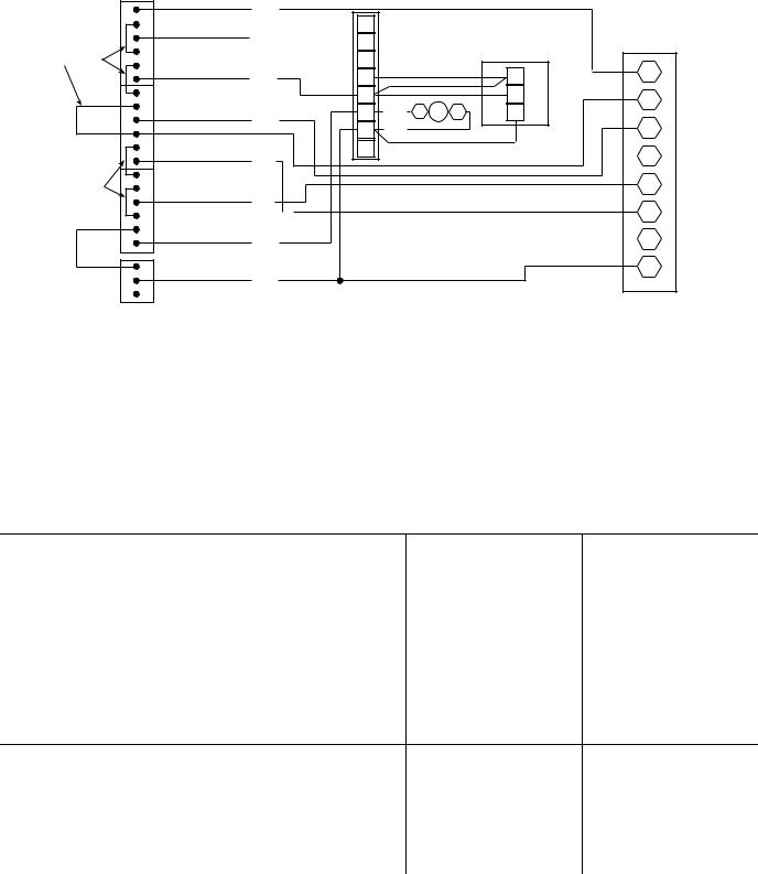
Fig. 2G — Typical PremierLink™ Control Wiring — 38AQ007 Units
PremierLink Connections
|
|
|
|
PWR |
RED |
|
|
|
|
|
|
|
|
|
|
HS3/EXH/RVS |
ORN CR |
|
|
|
|
|
|
|
|
RED |
|
|
|
|
|
|
|
HS2 |
PNK |
DUALFORCUT |
TRANSFORMER EQUIPTMENT |
RELAYS |
|
|
|
|
|
|
|||
|
|
RED |
|
|
|
|
|
|
|
HS1 |
WHT |
|
|
|
|
|
|
|
|
|
|
CMP2 |
BLU |
|
|
|
|
|
|
|
|
RED |
|
CMP1 |
|
|
|
|
|
YEL |
|
CUTTO ISOLATE |
CONTROLLER POWER |
PWR |
|
|
|
J1 |
|
|
|||
|
|
RED |
|
|
|
|
|
|
J8 |
FAN |
GRN |
|
|
|
|
|
|
BRN
LEGEND
CR — Control Relay (Field-Supplied)
IFC — Indoor-Fan Contactor
IAQ — Indoor-Air Quality
LLSV — Liquid LIne Solenoid Valve
NOTES:
|
40RM Connections |
38AQS008 |
||
|
|
|
Terminal |
|
|
|
|
Board (TB) |
|
R |
|
|
|
|
Y1 |
40RM, 40RMQ, 40RMS |
|
||
Y2 |
|
HEAT ACCESSORY |
|
|
|
|
|
||
W1 |
|
W1 |
R |
|
|
|
|||
W2 |
|
W2 |
Y1 |
|
G |
WHT C1 IFC C2 |
C |
||
|
||||
C |
WHT |
|
Y2 |
|
X |
|
|
W1 |
|
|
|
|
||
|
|
|
CR |
|
|
|
|
W2 |
|
|
|
LLSV |
G |
|
|
|
|
C |
|
|
|
|
X |
|
1.Configure AC to “1” for heat pump units.
2.Configure AUXOUT to “3” for reversing valve.
3.Configure PremierLink control for 2-stage heat and single-stage cool.
4.When using controller for DCV, if IAQ priority is set to HIGH, the controller will use a stage of heat for temperature tempering. If priority is set to LOW, no tempering will occur. If IAQ is high priority, wire HS2 to W1. If not, wire HS1 to W1.
Fig. 2H — Typical PremierLink Control Wiring — 38AQS008 and 38ARQ008,012 Units
7
|
|
|
|
PremierLink Connections |
|
|
40RMQ Connections |
38AQS012-016 |
||
CAPORREMOVE OFENDTHIS |
JUMPER |
|
RED |
|
|
Y2 |
|
|
Terminal |
|
|
PWR |
|
|
|
Board (TB2) |
|||||
|
|
|
|
|
|
|
|
|
||
|
|
|
|
|
RED |
|
|
|
|
|
|
|
|
|
|
|
|
|
|
|
|
|
|
|
|
|
HS3/EXH/RVS |
|
R |
|
|
|
|
|
|
|
|
ORN |
Y1 |
|
|
|
|
|
|
|
|
|
|
40RM, 40RMQ, 40RMS |
|
|||
|
|
|
|
|
|
|
|
|||
|
|
|
|
|
|
|
|
|
HEAT ACCESSORY |
|
|
|
|
|
|
HS2 |
PNK |
W1 |
|
W1 |
R |
|
DUALFORCUT |
TRANSFORMER |
EQUIPTMENT |
RELAYS |
|
|
|
|||
|
|
|
W2 |
|
W2 |
B |
||||
|
|
|
|
RED |
|
|
||||
|
|
|
|
|
G |
WHT C1 IFC C2 |
C |
|||
|
|
|
|
|
HS1 |
WHT |
|
|||
|
|
|
|
|
|
C |
WHT |
|
W1 |
|
|
|
|
|
|
|
|
|
|||
|
|
|
|
|
CMP2 |
|
X |
|
|
|
|
|
|
|
|
BLU |
|
|
|
|
|
|
|
|
|
|
|
|
|
|
|
|
|
|
|
|
RED |
|
|
|
|
|
Y1 |
|
|
|
|
CMP1 |
|
|
|
|
|
|
|
|
|
|
|
YEL |
|
|
|
|
|
|
|
|
|
|
|
|
|
|
Y2 |
|
TOCUT |
ISOLATE |
CONTROLLER |
POWER |
PWR |
J1 |
|
|
|
|
|
|
|
|
|
|
||||||
|
|
|
|
RED |
|
|
|
|
|
|
|
|
|
|
|
FAN |
GRN |
|
|
|
G |
|
|
|
|
|
J8 |
|
|
|
|
|
|
|
|
|
|
|
|
|
|
|
|
|
|
|
|
|
|
|
|
|
|
C |
|
|
|
|
|
|
BRN |
|
|
|
|
|
|
|
|
LEGEND |
|
|
|
|
|
|
IAQ — Indoor-Air Quality
IFC — Indoor-Fan Contactor
NOTES:
1.Configure AC to “1” for heat pump or “0” for air conditioner.
2.When using controller for DCV, if IAQ priority is set to HIGH, the controller will use a stage of heat for temperature tempering. If priority is set to LOW, no tempering will occur.
3.For air conditioners, use HS1 for IAQ tempering.
4.For heat pumps, use HS2 for IAQ tempering.
Fig. 2I — Typical PremierLink™ Control Wiring — 38AQS012-016 Units
Table 1 — PremierLink Controller Inputs and Outputs
INPUTS |
POWER |
TERMINAL(S) |
SPACE TEMPERATURE (SPT) |
AI (10K Thermistor) |
J6-7, J6-6 |
SET POINT ADJUSTMENT (STO) |
AI (10K Thermistor) |
J6-5, J6-6 |
SUPPLY AIR TEMPERATURE (SAT) |
AI (10K Thermistor) |
J6-3, J6-4 |
OUTDOOR AIR TEMPERATURE (OAT) |
AI (10K Thermistor) |
J6-1, J6-2 |
IAQ SENSOR (IAQI) |
(4-20 mA) |
J5-5, J5-6 |
OUTDOOR AQ SENSOR (OAQ) |
(4-20 mA) |
J5-2, J5-3 |
REMOTE TIME CLOCK (RMTOCC) |
DI (24 VAC) |
J4-11, J4-12 |
COMPRESSOR LOCKOUT (CMPSAFE) |
DI (24 VAC) |
J4-9, J4-10 |
FIRE SHUTDOWN (FSD) |
DI (24 VAC) |
J4-7, J4-8 |
SUPPLY FAN STATUS (SFS) |
DI (24 VAC) |
J4-5, J4-6 |
NOT USED |
|
|
ENTHALPY STATUS (ENTH) |
DI (24 VAC) |
J4-1, J4-2 |
|
OUTPUTS |
POWER |
TERMINAL(S) |
ECONOMIZER (ECONPOS) |
4-20 mA |
J9-1, J9-2 |
|
FAN (SF) |
DO Relay (24 VAC, 1A) |
J8-18 |
|
COOL STAGE 1 (CMP1) |
DO Relay (24 VAC, 1A) |
J8-15 |
|
COOL STAGE 2 (CMP2) |
DO Relay (24 VAC, 1A) |
J8-12 |
|
HEAT STAGE 1 (HS1) |
DO Relay (24 VAC, 1A) |
J8-9 |
|
HEAT STAGE 2 (HS2) |
DO Relay (24 VAC, 1A) |
J8-6 |
|
HEAT 3/EXHAUST/REVERSING VALVE (HS3/EXH/RVS) |
DO Relay (24 VAC, 1A) |
J8-3 |
|
|
LEGEND |
|
|
AI |
— Analog Input |
|
|
DI |
— Digital Input |
|
|
DO — Digital Output |
|
|
|
8
Table 2 — Color Code Recommendations
SIGNAL TYPE |
CCN BUS WIRE |
CCN PLUG PIN |
|
COLOR |
NUMBER |
||
|
|||
+ |
Red |
1 |
|
Ground |
White |
2 |
|
– |
Black |
3 |
Install Sensors (See Fig. 3-10) — The PremierLink™ controller can be used with either the T58 Communicating sensor or any combination of CO2 and space temperature sensors. Refer to the instructions supplied with each sensor for electrical requirements.
NOTE: All sensors are field-installed accessories.
SPACE TEMPERATURE (SPT) SENSOR INSTALLATION — There are three types of SPT sensors available from Carrier: The 33ZCT55SPT space temperature sensor with timed override button, the 33ZCT56SPT space temperature sensor with timed override button and set point adjustment, and the 33ZCT58SPT T58 communicating room sensor with timed override button, set point adjustment, and manual fan control.
The space temperature sensors are used to measure the building interior temperature. The T58 communicating room sensors measure and maintain room temperature by communicating with the controller. Sensors should be located on an interior building wall. The sensor wall plate accommodates the NEMA (National Electrical Manufacturers Association) standard 2 x 4 junction box. The sensor can be mounted directly on the wall surface if acceptable by local codes.
Do not mount the sensor in drafty locations such as near air conditioning or heating ducts, over heat sources such as baseboard heaters, radiators, or directly above wall-mounted lighting dimmers. Do not mount the sensor near a window which may be opened, near a wall corner, or a door. Sensors mounted in these areas will have inaccurate and erratic sensor readings.
The sensor should be mounted approximately 5 ft from the floor, in an area representing the average temperature in the space. Allow at least 4 ft between the sensor and any corner and mount the sensor at least 2 ft from an open doorway. The SPT sensor wires are to be connected to terminals in the unit main control board.
Install the sensor as follows:
1.Locate the two Allen type screws at the bottom of the sensor.
2.Turn the two screws clockwise to release the cover from the sensor wall mounting plate.
3.Lift the cover from the bottom and then release it from the top fasteners.
4.Feed the wires from the electrical box through the opening in the center of the sensor mounting plate.
5.Using two no. 6-32 x 1 mounting screws (provided with the sensor), secure the sensor to the electrical box.
NOTE: Sensor may also be mounted directly on the wall using 2 plastic anchors and 2 sheet metal screws (field-supplied).
6.Use 20 gage wire to connect the sensor to the controller. The wire is suitable for distances of up to 500 ft. Use a three-conductor shielded cable for the sensor and set point adjustment connections. The standard CCN communication cable may be used. If the set point adjustment (slidebar) is not required, then an unshielded, 18 or 20 gage, two-conductor, twisted pair cable may be used.
The CCN network service jack requires a separate, shielded CCN communication cable. Always use separate cables for CCN communication and sensor wiring. (Refer to Fig. 5 for wire terminations.)
7.Replace the cover by inserting the cover at the top of the mounting plate first, then swing the cover down over the lower portion. Rotate the two Allen head screws counterclockwise until the cover is secured to the mounting plate and locked in position.
NOTE: See Table 3 for thermistor resistance vs temperature values.
Wiring the Space Temperature Sensor — To wire the sensor, perform the following (see Fig. 3-5):
1.Identify which cable is for the sensor wiring.
2.Strip back the jacket from the cables for at least 3 inches.
Strip 1/4-in. of insulation from each conductor. Cut the shield and drain wire from the sensor end of the cable.
3.Connect the sensor cable as follows:
a.Connect one wire from the cable to (BLU) wire on J6-7 analog connector on the controller. Connect the other end of the wire to the left terminal on the SEN terminal block of the sensor.
b.Connect another wire from the cable to (BRN) J6-6 analog connector on the controller. Connect the other end of the wire to the remaining open terminal on the SEN terminal block.
c.On 33ZCT56SPT thermostats, connect the remaining wire to the (BLK) STO on J6-5 connector on the controller. Connect the other end of the wire to the SET terminal on the sensor.
d.In the control box, install a no. 10 ring type crimp lug on the shield drain wire. Install this lug under the mounting screw of the PremierLink controller.
e.On 33ZCT56SPT thermostats install a jumper between the two center terminals (right SEN and left SET). See Fig. 4.
f.Refer to Fig. 5 for 33ZCT58SPT thermostat wiring. Once the T58 sensor is powered up, all of the graphic icons on the LCD (liquid crystal display) display will be energized for a few seconds. The graphical icons will then turn off and the T58 sensor will energize the three-digit numeric display. The value “58” will be displayed for two seconds. After 2 seconds, the LCD will display the default space temperature value.
NOTE: See Fig. 6 for space temperature sensor averaging.
9
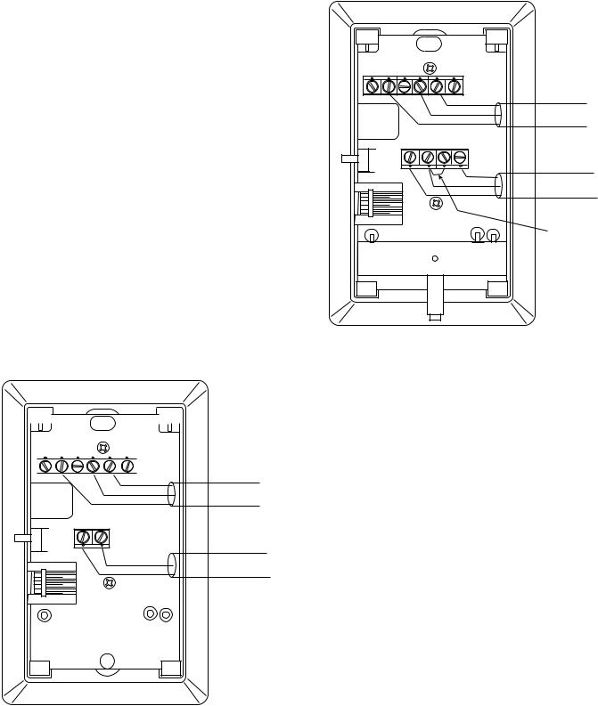
Table 3 — Thermistor Resistance vs Temperature Values for Space Temperature Sensor,
Supply Air Temperature Sensor, and
Outdoor Air Temperature Sensor
|
TEMP |
|
|
TEMP |
RESISTANCE |
||||||||
|
|
(C) |
|
|
(F) |
(Ohms) |
|||||||
|
|
–40 |
|
|
–40 |
335,651 |
|||||||
|
|
–35 |
|
|
–31 |
242,195 |
|||||||
|
|
–30 |
|
|
–22 |
176,683 |
|||||||
|
|
–25 |
|
|
–13 |
130,243 |
|||||||
|
|
–20 |
|
|
|
–4 |
96,974 |
||||||
|
|
–15 |
5 |
|
|
72,895 |
|||||||
|
|
–10 |
14 |
|
|
55,298 |
|||||||
|
|
–5 |
23 |
|
|
42,315 |
|||||||
0 |
|
|
|
32 |
|
|
32,651 |
||||||
5 |
|
|
|
41 |
|
|
25,395 |
||||||
10 |
|
|
|
50 |
|
|
19,903 |
||||||
15 |
|
|
|
59 |
|
|
15,714 |
||||||
20 |
|
|
|
68 |
|
|
12,494 |
||||||
25 |
|
|
|
77 |
|
|
10,000 |
||||||
30 |
|
|
|
86 |
|
|
8,056 |
||||||
35 |
|
|
|
95 |
|
|
6,530 |
||||||
40 |
|
|
|
104 |
|
|
5,325 |
||||||
45 |
|
|
|
113 |
|
|
4,367 |
||||||
50 |
|
|
|
122 |
|
|
3,601 |
||||||
55 |
|
|
|
131 |
|
|
2,985 |
||||||
60 |
|
|
|
140 |
|
|
2,487 |
||||||
65 |
|
|
|
149 |
|
|
2,082 |
||||||
70 |
|
|
|
158 |
|
|
1,752 |
||||||
|
|
|
|
|
|
|
|
|
|
|
|
|
|
|
|
|
|
|
|
|
|
|
|
|
|
|
|
|
|
|
|
|
|
|
|
|
|
|
|
|
|
|
|
|
|
|
|
|
|
|
|
|
|
|
|
1 |
2 |
3 |
4 |
5 |
6 |
RED(+) |
|
|
|
|
|
|
|
|
|
|
|
|
|
|
WHT(GND) |
CCN COM |
|
|
|
|
|
|
|
BLK(-) |
|
|
|
|
|
|
|
|
|
|
|
|
SEN |
|
|
|
|
|
SW1 |
|
|
|
|
|
|
|
|
|
|
|
BRN (GND) |
SENSOR WIRING |
|
|
|
|
|
|
BLU (SPT) |
|
|
Fig. 3 — Space Temperature Sensor
Typical Wiring (33ZCT55SPT)
1 |
2 |
3 |
4 |
5 |
6 |
RED(+) |
|
|
|
|
|
|
|
|
|
|
|
|
|
|
WHT(GND) |
CCN COM |
|
|
|
|
|
|
|
BLK(-) |
|
|
|
|
|
|
|
|
|
|
|
|
SEN |
|
SET |
|
|
|
SW1 |
|
|
|
|
BLK |
|
|
|
|
|
|
|
|
|
|
|
|
|
|
|
(T56) |
|
|
|
|
|
|
BRN (GND) |
SENSOR WIRING |
|
|
|
|
|
|
BLU (SPT) |
|
|
|
|
|
|
|
|
|
JUMPER |
|
|
|
|
|
|
|
TERMINALS |
|
|
|
|
|
|
|
AS SHOWN |
Cool Warm
Fig. 4 — Space Temperature Sensor
Typical Wiring (33ZCT56SPT)
SUPPLY AIR TEMPERATURE (SAT) SENSOR INSTALLATION — The 33ZCSENSAT supply air temperature sensor is required for controller operation. The sensor consists of a thermistor encased within a stainless steel probe. The SAT sensor probe is 6-in. nominal length with 114 in. of unshielded, 2-conductor 18 AWG twisted-pair cables. The sensor temperature range is –40 to 245 F with a nominal resistance of 10,000 ohms at 77 F. The sensor measures accuracy of ±0.36 F. The SAT sensor is supplied with a gasket and 2 self-drilling mounting screws.
NOTE: The sensor must be mounted in the discharge of the unit, downstream of the cooling coil and heat exchanger. Be sure the probe tip does not come in contact with any of the unit surfaces. See Fig. 11 for mounting location.
Do not run sensor or relay wires in the same conduit or raceway with Class 1 AC service wiring. Do not abrade, cut, or nick the outer jacket of the cable. Do not pull or draw cable with a force that may harm the physical or electrical properties. Avoid splices in any control wiring.
Perform the following steps to connect the SAT sensor to the PremierLink™ controller:
1.Locate the opening in the control box. Pass the sensor probe through the hole.
2.Drill or punch a 1/2-in. hole in the supply air duct.
3.Use two field-supplied, self-drilling screws to secure the sensor probe to the duct.
4.Connect the sensor leads to the PremierLink controller’s wiring harness J6-3,4 board at the terminals labeled SAT (ORN) and GND (BRN).
10
|
FIELD WIRING |
|
|
T58 SENSOR |
|
|
|
VAC |
|
J4-3 (24 VAC) |
|
|
24 VAC |
|
|
COM |
|
J6-6 SDT (COM) |
|
CCN- |
BLACK (-) |
|
|
GND |
WHITE (GND) |
CCN |
|
COM |
|||
|
|
||
CCN+ |
RED (+) |
|
|
|
BLACK (-) |
|
|
|
WHITE (GND) |
J2 |
|
|
(COM) |
||
|
|
||
|
RED (+) |
|
Fig. 5 — T58 Communicating Sensor
Typical Wiring (33ZCT58SPT)
Perform the following steps if state or local code requires the use of conduit, or if your installation requires a cable length of more than 8 ft:
1.Secure the probe to the duct with two field-supplied selfdrilling screws.
2.If you are extending cable length beyond 8 ft, use plenum rated, 20 AWG, twisted pair wire.
3.Connect the sensor leads to the PremierLink™ controller’s wiring harness terminal board at the terminals labeled SAT (ORN) and GND (BRN).
4.Neatly bundle and secure excess wire.
INDOOR AIR QUALITY CO2 SENSOR INSTALLATION (IAQ) — The indoor air quality sensor accessory monitors carbon dioxide (CO2) levels. This information is used to monitor IAQ levels. Three types of sensors are provided. The wall sensor can be used to monitor the conditioned air space. Sensors use infrared technology to measure the levels of CO2 present in the air. The wall sensor is available with or without an LCD readout to display the CO2 level in ppm.
The CO2 sensors are all factory set for a range of 0 to 2000 ppm and a linear mA output of 4 to 20. Refer to the instructions supplied with the CO2 sensor for electrical requirements and terminal locations.
To accurately monitor the quality of the air in the conditioned air space, locate the sensor near a return air grille (if present) so it senses the concentration of CO2 leaving the space. The sensor should be mounted in a location to avoid direct breath contact.
Do not mount the IAQ sensor in drafty areas such as near supply ducts, open windows, fans, or over heat sources. Allow at least 3 ft between the sensor and any corner. Avoid mounting the sensor where it is influenced by the supply air; the sensor gives inaccurate readings if the supply air is blown directly onto the sensor or if the supply air does not have a chance to mix with the room air before it is drawn into the return airstream.
Wiring the Indoor Air Quality Sensor — To wire the sensors after they are mounted in the conditioned air space or outdoor location, see Fig. 7 and 8 and the instructions shipped with the sensors. For each sensor, use two 2-conductor 18 AWG
(American Wire Gage) twisted-pair cables (unshielded) to connect the separate isolated 24 vac power source to the sensor and to connect the sensor to the control board terminals. To connect the sensor to the control, identify the positive (4 to 20 mA) and ground (SIG COM) terminals on the sensor. Connect the 4-20 mA terminal to terminal IAQ (RED) and connect the SIG COM terminal to terminal GND (BRN).
OUTDOOR AIR QUALITY CO2 SENSOR INSTALLATION (OAQ) — The Outdoor Air CO2 sensor is designed to monitor carbon dioxide (CO2) levels in the air and interface with the ventilation damper in an HVAC system. The OAQ sensor is packaged with an outdoor cover. See Fig. 12 and 13.
The outdoor air CO2 sensor must be placed in an area that is representative of the entire conditioned space. A mounting height of 6 feet is recommended. For installation where it is not necessary to reach the control, it may be mounted higher on the wall or on the ceiling, provided the location represents a good sampling of air.
Wiring the Outdoor Air CO2 Sensor — Power requirements are 18 to 36 vac RMS 50/60 Hz; 18 to 42 vdc polarity protected/ dependent; and 70 mA average, 100 mA peak at 24 vdc. All system wiring must be in compliance with all applicable local and national codes. A dedicated power supply is required for this sensor. A two-wire cable is required to wire the dedicated power supply for the sensor. The two wires should be connected to the power supply and terminals 1 and 2. To connect the sensor to the control, identify the positive (4 to 20 mA) and ground (SIG COM) terminals on the sensor. Connect the 4 to 20 mA terminal OAQ (BLU) terminal J5-2. Connect the SIG COM terminal to terminal GND (BRN) terminal J5-3. See Fig. 12.
OUTDOOR AIR TEMPERATURE SENSOR (Fig. 14-17) — The OAT sensor must be located properly. The sensor must be installed immediately upstream from outdoor air damper where it will accurately sense the temperature of the outdoor air entering the mixing box. See Fig. 14 and 15. For applications without economizer, the sensor may be located in the outdoor air duct near the outdoor air intake (Fig. 15) or on the exterior of the building. The thermistor has a range of –40 to 245 F and a resistance of 10,000 ohms at 77 F.
Do not mount the sensor in direct sunlight. Inaccurate readings may result. Do not mount the sensor near the exhaust from air-handling units or compressors, near leakage drafts of indoor air, or near shrubbery or trees, or under direct water runoff.
If the sensor is to be mounted in the outdoor air duct, a fieldsupplied 2 x 4-in. by 11/2-in. deep electrical box is required. Remove the cover and enter the knockout from the rear of the box. Install the sensor through the opening so that the sensor leads are inside the electrical box. Secure the sensor to the electrical box using a field-supplied 1/2-in. conduit nut. Drill a 13/16-in. hole in the outdoor air duct about a foot upstream of the outdoor air damper. Apply a 1/4-in. bead of silicone type sealer around the opening and install the sensor through the hole. Secure the electrical box to the duct using 2 fieldsupplied, No. 10 sheet metal screws. See Fig. 17.
If the sensor is installed outdoors, a field-supplied 1/2-in. LB type conduit body, gasket, cover, and 1/2-in. EMT compression connector are required. Install the OAT sensor into the opening at the end of the LB conduit body. Install the 1/2-in. EMT connector into the rear opening. Tighten each securely to prevent water leakage into the assembly. Mount the assembly onto the 1/2-in. EMT conduit and secure by tightening the compression connector nut. After the sensor wiring is completed, secure the gasket and cover in place using the screws provided with the cover. See Fig. 16.
11
|
|
RED |
RED |
|
|
|
BLK |
BLK |
|
J6 |
RED |
RED |
RED |
|
6 |
||||
|
|
|
||
7 |
BLK |
BLK |
BLK |
|
|
|
|
SENSOR 1 |
SENSOR 2 |
SENSOR 3 |
SPACE TEMPERATURE AVERAGING — 4 SENSOR APPLICATION |
||
J6 |
RED |
RED |
RED |
||
6 |
|
|
BLK |
BLK |
BLK |
7 |
|
|
BLK |
SENSOR 1 |
SENSOR 2 |
RED |
|
|
|
RED |
RED |
|
BLK |
BLK |
|
SENSOR 4 |
SENSOR 5 |
BLK |
RED |
|
LEGEND |
RED |
RED |
Factory Wiring |
BLK |
BLK |
Field Wiring |
|
|
|
SENSOR 7 |
SENSOR 8 |
SPACE TEMPERATURE AVERAGING — 9 SENSOR APPLICATION
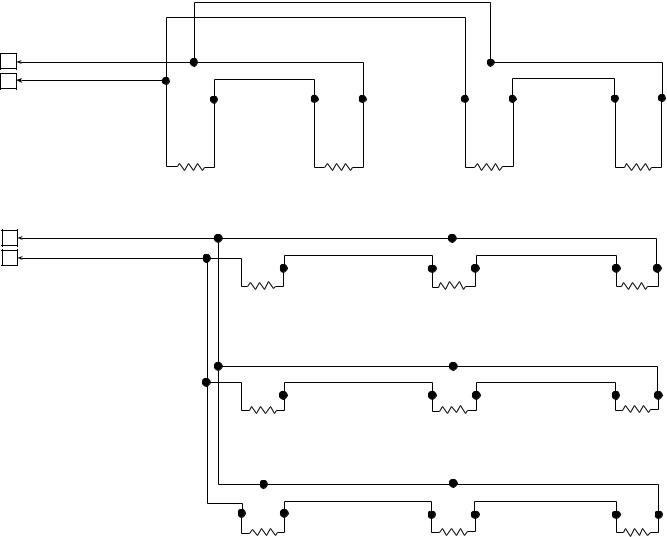
Fig. 6 — Space Temperature Averaging
SENSOR 4
SENSOR 3
SENSOR 6
SENSOR 9
12

13
LEGEND
OAT — Outdoor Air Temperature Sensor
SAT — Supply Air Temperature Sensor
SPT — Space Temperature Sensor
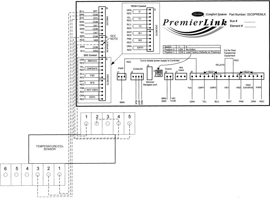
Fig. 7 — PremierLink™ Controller and Sensor Wiring — 33ZCT55SPT, 33ZCT56SPT, 33ZCT58SPT Space Temperature Sensors; 33ZCSENSAT Supply Air Temperature Sensor;
33ZCSENCO2 (Outdoor), and 33ZCT55CO2, 33ZCT56CO2 (Indoor) Air Quality Sensors
14
NOTE: No wire is connected to connector J-5 pin 4. You must relocate a wire from an unused terminal. Typically one of the red wires from connector J-4 may be used for this purpose. This pin on J-5 provided 24 VDC power to the combo sensor.
Fig. 8 — PremierLink™ Controller Wiring — Combination Temperature and CO2 Sensor — 33ZCT55CO2, 33ZCT56CO2
 Loading...