


ERVCCSVB1100, ERVCCSHB1100
HRVCCSVB1100, HRVCCSHB1100
Energy / Heat Recovery Ventilator
Installation Instructions
NOTE: Read the entire instruction manual before starting the installation.
TABLE OF CONTENTS
PAGE SAFETY CONSIDERATIONS . . . . . . . . . . . . . . . . . . . . . . . . . 1 INTRODUCTION . . . . . . . . . . . . . . . . . . . . . . . . . . . . . . . . . . . 2 INSTALLATION CONSIDERATIONS . . . . . . . . . . . . . . . . . . . 2 COMPONENT DESCRIPTION . . . . . . . . . . . . . . . . . . . . . . . . 2 UNIT INSTALLATION . . . . . . . . . . . . . . . . . . . . . . . . . . . . . . . 3 WALL CONTROL . . . . . . . . . . . . . . . . . . . . . . . . . . . . . . . . . . . 4
OPERATING THE ERV/HRV WITH
THE INFINITY CONTROL . . . . . . . . . . . . . . . . . . . . . . . . . . . 6 ELECTRICAL CONNECTIONS . . . . . . . . . . . . . . . . . . . . . . . . 6 ACCESSORIES . . . . . . . . . . . . . . . . . . . . . . . . . . . . . . . . . . . . . 6 BALANCING ERV/HRV . . . . . . . . . . . . . . . . . . . . . . . . . . . . . . 7 VENTILATION EVALUATION . . . . . . . . . . . . . . . . . . . . . . . . 8 CONTROL BOARD OPERATION . . . . . . . . . . . . . . . . . . . . . . 8 CARE AND MAINTENANCE . . . . . . . . . . . . . . . . . . . . . . . . . 8 TROUBLESHOOTING . . . . . . . . . . . . . . . . . . . . . . . . . . . . . . . 9
1.Fresh air to building port
2.Exhaust air from building port
3.Fresh air from outside port
4.Exhaust air to outside port
A08103
Fig. 1 - ERV/HRV Unit (Top Port)
A05330
Fig. 2 - ERV/HRV Unit (Side Port)
SAFETY CONSIDERATIONS
Improper installation, adjustment, alteration, service, maintenance, or use can cause explosion, fire, electrical shock, or other conditions which may cause death, personal injury or property damage. Consult a qualified installer, service agency, or your distributor or branch for information or assistance. The qualified installer or agency must use factory-authorized kits or accessories when modifying this product. Refer to the individual instructions packaged with kits or accessories when installing.
Follow all safety codes. Wear safety glasses, protective clothing and work gloves. Have a fire extinguisher available. Read these instructions thoroughly and follow all warnings or cautions included in literature and attached to the unit. Consult local building codes and the current editions of the National Electrical Code (NEC) NFPA 70.
In Canada, refer to the current editions of the Canadian Electrical Code CSA C22.1.
Recognize safety information. This is the safety-alert symbol  . When you see this symbol on the unit and in instruction manuals, be alert to the potential for personal injury.
Understand the signal words DANGER, WARNING, and CAUTION. These words are used with the safety-alert symbol. DANGER identifies the most serious hazards which will result in severe personal injury or death. WARNING signifies hazards which could result in personal injury or death. CAUTION is used to identify unsafe practices which may result in minor personal injury or product and property damage. NOTE is used to highlight suggestions which will result in enhanced installation, reliability, or operation.

ERV / HRV
INTRODUCTION
The Energy/Heat Recovery Ventilator (ERV/HRV) is used to exchange indoor stale air with outside fresh air. The unit is equipped with a special energy/heat recovery core which transfers both sensible and/or latent heat between the fresh incoming air and stale exhaust air. The cross-flow design core allows entering and leaving air streams to transfer heat and/or latent energy without mixing (See Fig. 3).
|
FRESH AIR |
|
STALE AIR |
FROM OUTSIDE |
|
FROM BUILDING |
|
|
FRESH AIR |
STALE AIR |
|
TO BUILDING |
||
TO OUTSIDE |
||
|
A07460
ERV/HRV is installed in conjunction with a forced-air system, unit should be located next to (or close to) the indoor equipment.
COMPONENT DESCRIPTION
The following listed items are components of ERVCCSHA (See Fig. 4).
1.Exhaust-air connected to outdoor air exhaust hood.
2.Fresh-air intake connected to outdoor air inlet hood.
3.Fresh-air supply from ERV connected to return-air duct of forced-air system.
4.Mechanical filters trap dust contained in the air.
5.Energy recovery core is a cross-flow type. The core transfers heat between the 2 air streams.
6.Blowers bring in fresh-air from outside and exhaust staleair to outside.
7.Electronic control circuit ensures proper unit operation.
8.Stale air return from building connected to return-air duct system.
Fig. 3 - ERV/HRV Airflow During Air Exchange (Bottom view with access door removed)
The model operates at 2 airflows, 50 CFM in low speed and 100 CFM in high speed. This unit comes in two configurations, vertical or horizontal. Special attention should be given to duct application, balancing the ERV/HRV, and locating unit for easy access and routine maintenance.
INSTALLATION CONSIDERATIONS
Inspect Equipment
Move carton to final installation location. Remove ERV/HRV from carton taking care not to damage unit. Remove all packaging and inspect unit for damage. Remove parts bag from inside unit. File claim with shipping company if shipment is damaged or incomplete. Check to make sure ERV/HRV unit matches Fig. 1 or Fig. 2.
Select Location
The ERV/HRV should be located in a conditioned space and in close proximity to a fused power source. It should be easily accessible for routine maintenance.
If ERV/HRV is installed independent of a forced-air system, unit should be located near the center of the air distribution system. If
WALL CONTROL
W ARNING |
A VER TI SS EMENT |
|
|
Ri s k of electric s hoc k. Be fo re per fo rmin g |
Da nger d’électr ocution. Dé branchez |
||
an y maintenance or |
s ervici ng, al wa y s |
toujour s l’a pp areil av ant d’entre |
prendr e |
di s connect the unit fr |
om it s p ow er s our ce . |
de s tra vaux d’entretien ou de ré |
paration. |
|
|
CA UTIO N |
|
AT TENTION |
|
Un s cr ew both s cr ew s to open the electrical |
Dé viss er le s deux vi s p our ouvrir le com par timent |
||
|
com par tment . To com plete ly remo ve , detac h |
électrique |
. P our retirer com plètement , le |
|
|
fr om it s retention wire in s id e. |
détacher de |
s on fil de rétention intérieur . |
|
No light |
OFF orremote controled |
|
|
|
Amber light |
LOW speed |
|
|
Terminal |
Blinking light |
See User Manual |
|
|
|
Green ligh |
HIGH speed |
|
|
|
Sans lumière |
Arrêté ou contrôlé |
|
|
Connector |
Lumière ambre |
Basse vitesse |
l |
|
|
par contrôle mura |
|
|
||
Lumière verte |
Haute vitesse |
|
|
|
Clignotant |
Vo ir guide d’utilisation |
|
|
|
ERV ports on side (bottom view)
4 |
5 |
4 |
3 |
|
8 |
2 |
1 |
7 |
6 |
A05263
Fig. 4 - Conventional Horizontal Unit
See Fig. 5 for terminal connector block for wiring wall and timer controls.
CONTROL
CONNECTOR
BLACK
GREEN
RED
YELLOW
A |
B |
A07418
Fig. 5 - Control Connector
2
UNIT INSTALLATION
!CAUTION
UNIT DAMAGE HAZARD
Failure to follow this caution may result in equipment damage or improper operation.
Do not install ERV/HRV in a corrosive or contaminated atmosphere.
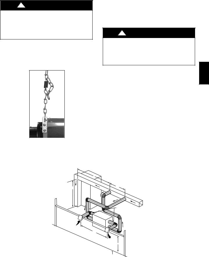
Mount Unit
The ERV/HRV can be suspended from floor joists using chains and 4 springs. Attach metal hanging bracket to all 4 sides of cabinet. (See Fig. 6.) The unit may be installed on a shelf if an isolation pad is provided to dampen vibration. Unit should always be installed as level as possible.
A05331
Fig. 6 - Chain Spring Installation
Independent System Application
In the absence of a forced-air system and a typical duct system layout, the ERV/HRV can be applied as an independent or stand
alone unit. To ensure comfort, this type of application involves running both fresh-air and return-air registers (or stale-air pickup registers) throughout the home.
Fresh-air registers are normally located in bedrooms, dining room, living room, and basement. It is recommended that registers be placed 6 to 12-in. (152 to 305mm) from the ceiling on an interior wall and airflow directed toward ceiling. If registers are floor installed, airflow should be directed toward the wall.
!WARNING
CARBON MONOXIDE POISONING HAZARD
Failure to follow this warning could result in personal injury or death.
Do not install return-air registers (or stale-air pickup registers) in same room as gas furnace or water heater.
Return-air (or stale-air pickup registers) are normally located to draw from kitchen, bathroom, basement, or other rooms where stale-air can exist.
Proper size and type of registers must be used to minimize pressure drop. The velocity of airflow through register should not be above 400 ft (122m) per minute.
Maximum length of duct for the system should be designed according to the highest speed of the unit. Refer to specifications listed in unit Product Data Digest for ventilation capacities.
Forced-Air Application
Most ERV/HRV applications will be installed in conjunction with new or existing forced-air system. To operate properly, the fresh-air supply and stale-air return from ERV/HRV connect directly to return-air duct system. This is how the ERV/HRV distributes fresh air and removes stale air from inside of building (See Fig. 7). For these installations, furnace or fan coil blower must be interlocked and operate continuously whenever ERV/HRV is energized. See Fig. 17 for interlock wiring detail.
NOTE: The fresh air from ERV/HRV is introduced into return-air duct at a point no less than 6 ft (1.8m) upstream of furnace or fan coil. This connection should be direct (See Fig. 7). This is to allow incoming fresh-air to mix before entering indoor equipment.
NOTE: A + B = Not less than 10 ft / 3 m
A
B
FURNACE
ERV
REAR
INLET HOOD
6 ft / 1.8 m
3 ft / .9 m MIN
INSULATED DUCT CONNECTING FRESH AIR & EXHAUST TO OUTSIDE
NOTE: Supply & exhaust ducts have internal balancing dampers that must be adjusted.
EXHAUST HOOD
18" / 457 mm
GROUND LEVEL
A07282
Fig. 7 - Exhaust Ventilation
ERV / HRV
3
ERV / HRV
Connect Ducts to ERV/HRV
!CAUTION
PROPERTY DAMAGE HAZARD
Failure to follow this caution may result in minor property damage from sweating duct or loss of unit efficiency and capacity.
If ERV/HRV duct work is installed in an unconditioned space, insulated flexible duct is required.
Insulated flexible duct is required on both fresh-air inlet and exhaust-air outlet ducts connecting to exterior wall. When using insulated flexible duct, the vapor barrier of the flexible ducts must be taped very tight to prevent condensation problems. To reduce pressure drop, stretch the flex duct and support it in a proper manner to avoid reduced airflow.
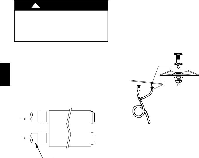
When connecting the ERV/HRV to a return-air duct system, insulated flexible duct can be used. However, when metal or rigid ducts are applied use approximately 18-in. (457mm) of flexible duct at ERV/HRV ports for fresh-air supply, and stale-air return. When using metal duct from fresh-air supply to system duct work, the metal duct should be insulated. (See Fig. 8.) This can act as a silencer when connecting ducts to return-air duct system. This should eliminate transmission of noise or vibration from unit to main duct system.
STALE-AIR
RETURN
FRESH-AIR
SUPPLY
FLEXIBLE DUCTS CONNECTING TO
RETURN-AIR DUCT SYSTEM
A08102
Fig. 8 - Flexible Duct Fit-Up
Locate and Install Exterior Hoods
IMPORTANT: To prevent condensation problems, insulated flexible ducts are required on both fresh-air inlet and exhaust-air outlet ducts connecting between ERV/HRV and exterior wall.
Fresh-air intake and stale-air exhaust must be separated by at least 6 ft (1.8m). Fresh-air intake must be positioned at least 10 ft (3m) from nearest dryer vent, furnace exhaust, driveway, gas meter, or oil fill pipe. Fresh-air intake must be positioned as far as possible from garbage containers and potential chemical fumes. When possible, it is advised to locate the intake and exhaust hoods on same side of house or building. The intake and exhaust hoods should never be located on interior corners or in dead air pockets (See Fig. 7). Both intake and exhaust hoods must be 18-in. (457mm) from ground and at least 12-in. (305mm) above anticipated snow level.
After selecting proper hood locations, make appropriate size hole through exterior wall, pass flexible duct through hole and insert hood tube into duct. Tape duct vapor barrier tightly around hood tube and insert assembly back into wall and fasten securely.
Condensate Drain
(For ERV, skip this step and continue to the next step.)
To connect condensate drain, proceed as follows:
1.Punch out holes in foam insulation and door, then insert sleeved grommets into bottom of unit using the gasket washer and nut. (See Fig. 9.)
2.Cut two sections of plastic tubing, about 12-in. / 305mm long and attach them to each drain.
3.Join the two short sections of plastic tubing to the “T” connector and the main tube as shown.
4.Make a loop in the tubing below the “T” connector to create a trap to prevent sewer gases from entering the ventilation system. (See Fig. 9.)
5.Connect unit drain to building’s main drain. Provide slight slope from unit for run-off.
A99268
Fig. 9 - Condensate Drain With Loop Trap (HRV Only)
WALL CONTROL
Types
Four remote wall control options are available:
1.Basic Control (see Table 1).
2.OneTouch Control
3.Standard Control (includes dehumidistat)
4.Latent Control (includes humidistat for use with ERV’s only)
Table 1 – Basic Control
MODE |
OPERATION |
DAMPER |
FAN |
|
POSITION |
SPEED |
|||
|
|
|||
|
|
|
|
|
Off |
Off |
Closed to outside |
Off |
|
|
|
|
|
|
Low |
Air exchange with |
Open to outside |
Low |
|
outside |
||||
|
|
|
||
|
|
|
|
|
Intermittent |
Air exchange with |
Open to outside |
Low |
|
outside |
||||
|
|
|
||
|
|
|
|
|
High |
Air exchange with |
Open to outside |
High |
|
outside |
||||
|
|
|
||
|
|
|
|
Location
The Standard Control and the Latent Control sense humidity and not temperature. They must be located in an area where they will continually monitor fresh air circulating within the home. Install ERV/HRV wall controls as close as possible to main system thermostat and follow same guidelines as installing a thermostat (locate approximately 5 ft (1.5m) above floor, mount on an inside partitioning wall, etc.)
Wiring
Remove top cover assembly from wall control and pass thermostat wire through hole located on back of control before attaching to wall. Connect Y, R, G, and B (yellow, red, green, and black)
4
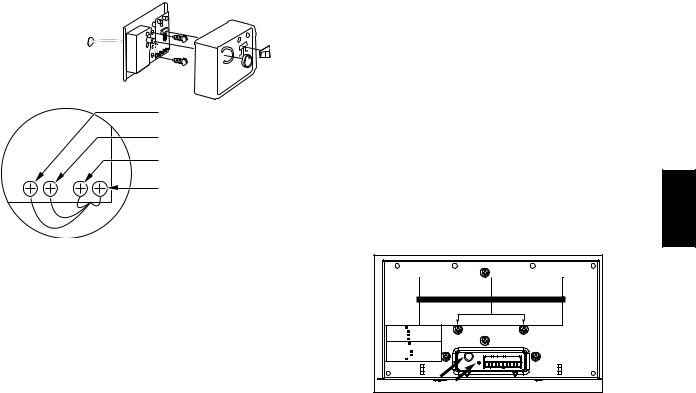
between wall control and ERV/HRV connector following color code. (See Fig. 5 and 10.) Replace top cover assembly.
NOTE: ERV/HRV wall control and circuit board operate on 12VDC.
|
|
YELLOW |
|
|
RED |
|
|
GREEN |
|
|
BLACK |
Y |
R |
GB |
A98383
Fig. 10 - Typical Wall Control
Operation
The Standard and Latent wall controls have 4 basic modes of operation, OFF, LOW, HIGH, and INTERMITTENT. Be sure that all modes of operation are fully functional. See Table 1 indicating standard control operation.
1.With switch off, ERV/HRV is inoperative and the LED is out.
2.With switch on LOW, ERV/HRV continuously exchanges air with outside. If control is satisfied, blower will run in low speed, otherwise, blower will run on high speed. The LED is illuminated all the time.
3.With switch on INTERMITTENT, the ERV/HRV exchanges air with outside on high-speed blower, and unit shuts down when control is satisfied. The ON LED is illuminated all the time, and AIR EXCHANGE LED is illuminated only when unit is running.
Humidity Selector
The humidity selector is a built-in control designed to properly control the level of humidity in the house during the winter and summer months. This control helps avoid condensation problems in upper northern regions where indoor humidity is a problem during the winter season.
NOTE: This control is not to be confused with a dehumidistat used during the summer months to control high relative indoor humidity.
Table 2 recommends humidity levels to avoid condensation.
Table 2 – Recommended Humidity Levels
OUTSIDE |
DOUBLE---PANE |
TRIPLE---PANE |
TEMPERATURE |
WINDOWS |
WINDOWS |
50°F / 10°C |
55% |
65% |
32°F / 0°C |
45% |
55% |
14°F / ---10°C |
35% |
45% |
---4°F / ---20°C |
30% |
45% |
---22°F / ---30°C |
25% |
35% |
OneTouch Control
The OneTouch Control can be used as the primary wall control for the ERV/HRV. This control will step through the modes of operation with consecutive presses of the button. The LED indicates which mode is currently selected, Off, Intermittent, Low, or High.
NOTE: OneTouch Control does not have a humidity selector.
NOTE: OneTouch Intermittent mode exchanges air on low speed for 20 minutes per hour.
Latent Control
NOTE: For Latent Controls used with ERV;s, to ensure highest degree of humidity control in cooling season, the INTERMITTENT mode should be used.
Integrated Control
All units are equipped with an integrated control, located under the unit, in front of the electrical compartment. Use the push button (1) to control the unit. The LED (2) will then shows on which mode the unit is in. Integrated Control overrides Wall Control function. When LED is off, ventilator responds to Wall Control command. See Fig. 11.
WARNING |
AVERTISSEMENT |
Risk of electric shock. Before performing |
Danger d’électrocution. Débranchez |
any maintenance or servicing, always |
toujours l’appareil avant d’entreprendre |
disconnect the unit from its power source. |
des travaux d’entretien ou de réparation. |
|
CAUTION |
ATTENTION |
|
Unscrew both screws to open the electrical |
Dévisser les deux vis pour ouvrir le compartiment |
|
compartment. To completely remove, detach |
électrique. Pour retirer complètement, le |
|
from its retention wire inside. |
détacher de son fil de rétention intérieur. |
No light |
OFF or remote controled |
|
Amber light |
LOW speed |
|
Green ligh |
HIGH speed |
|
Blinking light |
See User Manual |
|
Sans lumière |
Arrêté ou contrôlé |
|
|
par contrôle mural |
|
Lumière ambre |
Basse vitesse |
|
Lumière verte |
Haute vitesse |
|
Clignotant |
Voir guide d’utilisation |
|
1 2
A07260
Fig. 11 - Integrated Control
Refer to table below to see how to operate the unit using its integrated control.
PRESS ON PUSH |
LED COLOR |
RESULTS |
|
BUTTON |
|||
|
|
||
|
|
|
|
Once |
Amber |
Unit is on Low |
|
Speed |
|||
|
|
||
|
|
|
|
Twice |
Green |
Unit is on High |
|
Speed |
|||
|
|
||
|
|
|
|
Three Times |
No Light |
Unit is OFF |
|
|
|
|
If a problem occurs during the unit operation, its integrated control LED (2) will blink. The color of the blinking light depends on the type of error detected. Refer to Troubleshooting for further details.
NOTE: The ERV/HRV may be controlled using the Infinity system control. The ERV/HRV may be connected using either a NIM or a 4-Zone Damper Module. See the appropriate instructions if using the NIM or a 4-Zone Damper Module for connection instructions.
The Infinity system control will simultaneously control the ERV/HRV and the indoor blower.
Push Button Timers may be used and are connected to the ERV/HRV. However, the Infinity system should be set to continuous fan to ensure that the fresh air is circulated in the home. In a Zoned System, at least one zone should be set to continuous fan.
ERV / HRV
5
 Loading...