


30GN040-420 Flotronic™ II Reciprocating Liquid Chillers
50/60 Hz
Controls, Operation, and
Troubleshooting
with Microprocessor Controls and Electronic Expansion Valves
CONTENTS
Page
SAFETY CONSIDERATIONS . . . . . . . . . . . . . . . . . . 2
GENERAL . . . . . . . . . . . . . . . . . . . . . . . . . . . . . . . . . . . 2
MAJOR SYSTEM COMPONENTS . . . . . . . . . . . . 2-5
Processor Module . . . . . . . . . . . . . . . . . . . . . . . . . . . 2
Low-Voltage Relay Module . . . . . . . . . . . . . . . . . . . 4
Electronic Expansion Valve Module . . . . . . . . . . . 4
Options Module . . . . . . . . . . . . . . . . . . . . . . . . . . . . . 4
Keypad and Display Module
(Also Called HSIO or LID) . . . . . . . . . . . . . . . . . . 4
Control Switch . . . . . . . . . . . . . . . . . . . . . . . . . . . . . . 4
Electronic Expansion Valve (EXV) . . . . . . . . . . . . 4
Thermostatic Expansion Valves (TXV) . . . . . . . . 4
Sensors . . . . . . . . . . . . . . . . . . . . . . . . . . . . . . . . . . . . . 5
Compressor Protection Control
Module (CPCS) . . . . . . . . . . . . . . . . . . . . . . . . . . . . 5
OPERATION DATA . . . . . . . . . . . . . . . . . . . . . . . . . . 5-46
Capacity Control . . . . . . . . . . . . . . . . . . . . . . . . . . . . 5
Head Pressure Control . . . . . . . . . . . . . . . . . . . . . . 24
·EXV UNITS
·TXV UNITS
Pumpout . . . . . . . . . . . . . . . . . . . . . . . . . . . . . . . . . . . 24
·EXV UNITS
·TXV UNITS
Keypad and Display Module
(Also Called HSIO or LID) . . . . . . . . . . . . . . . . . 24
·ACCESSING FUNCTIONS AND SUBFUNCTIONS
·AUTOMATIC DEFAULT DISPLAY
·AUTOMATIC DISPLAY OPERATION/DEFAULT DISPLAY
·KEYPAD OPERATING INSTRUCTIONS
·STATUS FUNCTION
·TEST FUNCTION
·HISTORY FUNCTION
·SET POINT FUNCTION
·SERVICE FUNCTION
·SCHEDULE FUNCTION
TROUBLESHOOTING . . . . . . . . . . . . . . . . . . . . . . 47-64
Checking Display Codes . . . . . . . . . . . . . . . . . . . . 47
Page
Unit Shutoff . . . . . . . . . . . . . . . . . . . . . . . . . . . . . . . . 48
Complete Unit Stoppage . . . . . . . . . . . . . . . . . . . . 48
Single Circuit Stoppage . . . . . . . . . . . . . . . . . . . . . 48
Lag Compressor Stoppage . . . . . . . . . . . . . . . . . . 48
Restart Procedure . . . . . . . . . . . . . . . . . . . . . . . . . . 48
· POWER FAILURE EXTERNAL TO THE UNIT
Alarms and Alerts . . . . . . . . . . . . . . . . . . . . . . . . . . 48
Compressor Alarm/Alert Circuit . . . . . . . . . . . . . 50
Electronic Expansion Valve (EXV) . . . . . . . . . . . 55
·EXV OPERATION
·CHECKOUT PROCEDURE
Thermostatic Expansion Valve (TXV) . . . . . . . . . 57
Thermistors . . . . . . . . . . . . . . . . . . . . . . . . . . . . . . . . 57
·LOCATION
·THERMISTOR REPLACEMENT (T1, T2, T7, T8)
Pressure Transducers . . . . . . . . . . . . . . . . . . . . . . 60
·TROUBLESHOOTING
·TRANSDUCER REPLACEMENT
Control Modules . . . . . . . . . . . . . . . . . . . . . . . . . . . . 63
·PROCESSOR MODULE (PSIO), 4IN/4OUT MODULE (SIO), LOW-VOLTAGE RELAY MODULE (DSIO-LV), AND EXV DRIVER MODULE (DSIO-EXV)
·RED LED
·GREEN LED
·PROCESSOR MODULE (PSIO)
·LOW-VOLTAGE RELAY MODULE (DSIO)
·4IN/4OUT MODULE (SIO)
ACCESSORY UNLOADER INSTALLATION . . . 64-68
Installation . . . . . . . . . . . . . . . . . . . . . . . . . . . . . . . . . 65
·040-110, 130 (60 Hz) UNITS (And Associated Modular Units)
·130 (50 Hz), 150-210 UNITS (And Associated Modular Units)
FIELD WIRING . . . . . . . . . . . . . . . . . . . . . . . . . . . . . 69,70
REPLACING DEFECTIVE PROCESSOR MODULE (PSIO) . . . . . . . . . . . . . . . . . . . . . . . . . . 70
Installation . . . . . . . . . . . . . . . . . . . . . . . . . . . . . . . . . 70
Manufacturer reserves the right to discontinue, or change at any time, speci®cations or designs without notice and without incurring obligations.
Book |
2 |
|
PC 903 |
Catalog No. 563-079 |
Printed in U.S.A. |
Form 30GN-3T |
Pg 1 |
7-95 |
Replaces: 30G-1T |
Tab |
5c |
|
|
|
|
|
|
|
|
|
|
|
|
|
|
|
|
|
|

SAFETY CONSIDERATIONS
Installing, starting up, and servicing this equipment can be hazardous due to system pressures, electrical components, and equipment location (roof, elevated structures, etc.). Only trained, quali®ed installers and service mechanics should install, start up, and service this equipment.
When working on this equipment, observe precautions in the literature, and on tags, stickers, and labels attached to the equipment, and any other safety precautions that apply. Follow all safety codes. Wear safety glasses and work gloves. Use care in handling, rigging, and setting this equipment, and in handling all electrical components.
Electrical shock can cause personal injury and death. Shut off all power to this equipment during installation and service. There may be more than one disconnect switch. Tag all disconnect locations to alert others not to restore power until work is completed.
This unit uses a microprocessor-based electronic control system. Do not use jumpers or other tools to short out components, or to bypass or otherwise depart from recommended procedures. Any short-to-ground of the control board or accompanying wiring may destroy the electronic modules or electrical components.
GENERAL
IMPORTANT: This publication contains controls, operation and troubleshooting data for 30GN040-420 Flotronic™ II chillers.
Circuits are identi®ed as circuits A and B, and compressors are identi®ed as A1, A2, etc. in circuit A, and B1, B2, etc. in circuit B.
Use this guide in conjunction with separate Installation Instructions booklet packaged with the unit.
The 30G Series standard Flotronic II chillers feature microprocessor-based electronic controls and an electronic expansion valve (EXV) in each refrigeration circuit.
NOTE: The 30GN040 and 045 chillers with a factoryinstalled brine option have thermal expansion valves (TXV) instead of the EXV.
Unit sizes 230-420 are modular units which are shipped as separate sections (modules A and B). Installation instructions speci®c to these units are shipped inside the individual modules. See Table 1 for a listing of unit sizes and modular combinations. For modules 230B-315B, follow all general instructions as noted for unit sizes 080-110. For all remaining modules, follow instructions for unit sizes 130-210.
Table 1 Ð Unit Sizes and Modular Combinations
UNIT MODEL |
NOMINAL |
SECTION A |
SECTION B |
30GN |
TONS |
UNIT 30GN |
UNIT 30GN |
040 |
40 |
Ð |
Ð |
045 |
45 |
Ð |
Ð |
050 |
50 |
Ð |
Ð |
060 |
60 |
Ð |
Ð |
070 |
70 |
Ð |
Ð |
080 |
80 |
Ð |
Ð |
090 |
90 |
Ð |
Ð |
100 |
100 |
Ð |
Ð |
110 |
110 |
Ð |
Ð |
130 |
125 |
Ð |
Ð |
150 |
145 |
Ð |
Ð |
170 |
160 |
Ð |
Ð |
190 |
180 |
Ð |
Ð |
210 |
200 |
Ð |
Ð |
230 |
220 |
150 |
080 |
245 |
230 |
150 |
090 |
255 |
240 |
150 |
100 |
270 |
260 |
170 |
100 |
290 |
280 |
190 |
110 |
315 |
300 |
210 |
110 |
330 |
325 |
170 |
170 |
360 |
350 |
190 |
190/170* |
390 |
380 |
210 |
190 |
420 |
400 |
210 |
210 |
|
|
|
|
*60 Hz units/50 Hz units.
The Flotronic II control system cycles compressor unloaders and/or compressors to maintain the selected leaving ¯uid temperature set point. It automatically positions the EXV to maintain the speci®ed refrigerant superheat entering the compressor cylinders. It also cycles condenser fans on and off to maintain suitable head pressure for each circuit. Safeties are continuously monitored to prevent the unit from operating under unsafe conditions. A scheduling function, programmed by the user, controls the unit occupied/unoccupied schedule. The control also operates a test program that allows the operator to check output signals and ensure components are operable.
The control system consists of a processor module (PSIO), a low-voltage relay module (DSIO-LV), 2 EXVs, an EXV driver module (DSIO-EXV), a 6-pack relay board, a keypad and display module (also called HSIO or LID), thermistors, and transducers to provide inputs to the microprocessor. A standard options module (SIO) is used to provide additional functions. See Fig. 1 for a typical 30GN Control Panel.
MAJOR SYSTEM COMPONENTS
Processor Module Ð This module contains the operating software and controls the operation of the machine. It continuously monitors information received from the various transducers and thermistors and communicates with the relay modules and 6-pack relay board to increase or decrease the active stages of capacity. The processor module
2

COMM 3 PWR

POINT NUMBER |
X X |
OF |
|
FIRST CHANNEL |
|
EXV |
LV |
STATUS |
STATUS |
COMM |
COMM |
J5
2 1 |
HK35AA002 |
&PotterBrumfield |
CZ770 |
5VDC |
-4 |
|
|
|
|
|
3+ |
COMM |
1 |
PWR |
|
|
COMM |
3 |
|
|
|
|
|
S1 |
J4 |
J4 |
|
|
S2 |
X X |
|
|
|
|
|
|
|
|
|
|
|
|
|
|
|
|
|
|
|
|
|
|
|
|
|
|
|
|
|
|
|
|
|
|
|
|
|
|
|
|
STAT |
EXPN |
7 |
8 |
9 |
|
|
|
HIST |
CLR SCHD |
4 |
5 |
6 |
|
SRVC |
SET |
1 |
2 |
3 |
|
|
TEST |
ENTR |
– |
0 |
• |
||
|
|
|
|
|
|
|
|
|
|
|
|
|
|
|
|
|
|
|
FUSE |
|
1 |
LOC AL/ |
SW1 |
|
|
|
|
|
|
|
|
|
ENABLE |
|
|
|
|
|
|
|
|
|
|
STOP |
|
|
|
|
|
|
|
|
|
|
CCN |
|
|
|
|
|
|
|
|
|
|
|
FUSE |
3 |
|
|
F |
U S E |
|
|
|
|
|
|
|
|
|
E |
|
F |
|
|
|
|
|
|
|
|
S |
|
SU |
|
|
|
|
|
|
|
|
U |
|
|
|
|
|
|
|
|
|
|
F |
|
E |
|
|
|
|
|
|
|
|
|
|
|
FUSE |
|
2 |
|
|
|
|
GFI |
- |
CO |
|
|
|
|
|
||
( |
5 |
AMP |
MAX |
) |
|
CB5 |
|
|
||
|
|
|
|
|
|
|
|
CB6 |
|
|
|
|
|
|
|
|
|
|
30GT510568 |
– |
|
EQUIP GND 
99NA505322 D
LEGEND
CCN Ð Carrier Comfort Network
TB Ð Terminal Block
Fig. 1 Ð 30GN Control Panel (040-110 Unit Shown)
3
also controls the EXV driver module (as appropriate), commanding it to open or close each EXV in order to maintain the proper superheat entering the cylinders of each lead compressor. Information is transmitted between the processor module and relay module, the EXV driver module, and the keypad and display module through a 3-wire communications bus. The options module is also connected to the communications bus.
For the Flotronic™ II chillers, the processor monitors system pressure by means of 6 transducers, 3 in each lead compressor. Compressor suction pressure, discharge pressure, and oil pressure are sensed. If the processor senses high discharge pressure or low suction pressure, it immediately shuts down all compressors in the affected circuit. During operation, if low oil pressure is sensed for longer than one minute, all compressors in the affected circuit are shut down. At startup, the oil pressure signal is ignored for 2 minutes. If shutdown occurs due to any of these pressure faults, the circuit is locked out and the appropriate fault code is displayed.
Low-Voltage Relay Module Ð This module closes contacts to energize compressor unloaders and/or compressors. It also senses the status of the safeties for all compressors and transmits this information to the processor.
Electronic Expansion Valve Module (If So Equipped) Ð This module receives signals from the processor and operates the electronic expansion valves.
Options Module Ð This module allows the use of Flotronic II features such as dual set point, remote reset, demand limit, hot gas bypass, and accessory unloaders. The options module also allows for reset and demand limit to be activated from a remote 4-20 mA signal. The options module is installed at the factory.
Keypad and Display Module (Also Called HSIO
or LID) Ð This device consists of a keypad with 6 function keys, 5 operative keys, 12 numeric keys, and an alphanumeric 8-character LCD (liquid crystal display). Key usage is explained in Accessing Functions and Subfunctions section on page 24.
Control Switch Ð Control of the chiller is de®ned by the position of the LOCAL/ENABLE-STOP-CCN switch. This is a 3-position manual switch that allows the chiller to be put under the control of its own Flotronic II controls, manually stopped, or put under the control of a Carrier Comfort Network (CCN). Switch allows unit operation as shown in Table 2.
In the LOCAL/ENABLE position, the chiller is under local control and responds to the scheduling con®guration and set point data input at its own local interface device (keypad and display module).
Table 2 Ð LOCAL/ENABLE-STOP-CCN
Switch Positions and Operation
SWITCH |
UNIT |
CONFIGURATION AND |
||
SET POINT CONTROL |
||||
POSITION |
OPERATION |
|
|
|
Keypad Control |
CCN Control |
|||
|
|
|||
STOP |
Unit Cannot Run |
Read/Write |
Read Only |
|
LOCAL/ENABLE |
Unit Can Run |
Read/Limited Write |
Read Only |
|
CCN Stop Ð |
Unit Cannot Run |
Read Only |
Read/Write |
|
Run Ð |
Unit Can Run |
Read Only |
Read/Limited |
|
Write |
||||
|
|
|
||
|
|
|
|
|
In the CCN position, the chiller is under remote control and responds only to CCN network commands. The occupied/ unoccupied conditions are de®ned by the network. All keypad and display functions can be read at the chiller regardless of position of the switch.
CCN run or stop condition is established by a command from the CCN network. It is not possible to force outputs from the CCN network, except that an emergency stop command shuts down the chiller immediately and causes ``ALARM 52'' to be displayed.
Electronic Expansion Valve (EXV) Ð The microprocessor controls the EXV (if so equipped) through the EXV driver module. Inside the expansion valve is a linear actuator stepper motor.
The lead compressor in each circuit has a thermistor and a pressure transducer located in the suction manifold after the compressor motor. The thermistor measures the temperature of the superheated gas entering the compressor cylinders. The pressure transducer measures the refrigerant pressure in the suction manifold. The microprocessor converts the pressure reading to a saturated temperature. The difference between the temperature of the superheated gas and the saturation temperature is the superheat. The microprocessor controls the position of the electronic expansion valve stepper motor to maintain 30 F (17 C) superheat.
At initial unit start-up, the EXV position is at zero. After that, the microprocessor keeps accurate track of the valve position in order to use this information as input for the other control functions. The control monitors the superheat and the rate of change of superheat to control the position of the valve. The valve stroke is very large, which results in very accurate control of the superheat.
Thermostatic Expansion Valves (TXV) Ð Model 30GN040 and 045 units with factory-installed brine option are equipped with conventional thermostatic expansion valves with liquid line solenoids. The liquid line solenoid valves are not intended to be a mechanical shut-off. When service is required, use the liquid line service valve to pump down the system.
4
The TXV is set at the factory to maintain approximately 8 to 12° F (4.4 to 6.7° C) suction superheat leaving the cooler by monitoring the proper amount of refrigerant into the cooler. All TXVs are adjustable, but should not be adjusted unless absolutely necessary. When TXV is used, thermistors T7 and T8 are not required.
The TXV is designed to limit the cooler saturated suction temperature to 55 F (12.8 C). This makes it possible for unit to start at high cooler ¯uid temperatures without overloading the compressor.
Sensors Ð The Flotronic™ II chiller control system gathers information from sensors to control the operation of the chiller. The units use 6 standard pressure transducers and 4 standard thermistors to monitor system pressures and temperatures at various points within the chiller. Sensors are listed in Table 3.
Table 3 Ð Thermistor and Transducer Locations
|
THERMISTORS |
Sensor |
Location |
T1 |
Cooler Leaving Fluid Temp |
T2 |
Cooler Entering Fluid Temp |
T7 |
Compressor Suction Gas Temp Circuit A |
T8 |
Compressor Suction Gas Temp Circuit B |
T10 |
Remote Temperature Sensor (Accessory) |
|
PRESSURE TRANSDUCERS |
Sensor |
Location |
DPT-A |
Compressor A1 Discharge Pressure |
SPT-A |
Compressor A1 Suction Pressure |
OPT-A |
Compressor A1 Oil Pressure |
DPT-B |
Compressor B1 Discharge Pressure |
SPT-B |
Compressor B1 Suction Pressure |
OPT-B |
Compressor B1 Oil Pressure |
|
|
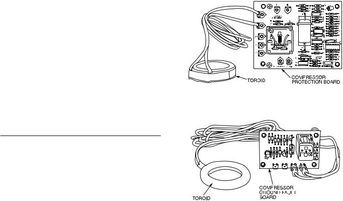
Compressor Protection Control Module (CPCS)
Ð Each compressor on models 30GN070 (50 Hz), 080110, and 230B-315B, has its own CPCS as standard equipment. See Fig. 2. All 30GN040-060 and 070 (60 Hz) units feature the CPCS as an accessory, and CR (control relay) as standard equipment. The 30GN130-210 and associated modular units have a CR as standard equipment. The CPCS or CR is used to control and protect the compressors and crankcase heaters. The CPCS provides the following functions:
·compressor contactor control
·crankcase heater control
·compressor ground current protection
·status communication to processor board
·high-pressure protection
The CR provides all of the same functions as the CPCS with the exception of compressor ground current protection. Ground current protection is accomplished by using a CGF (compressor ground fault module) in conjunction with the CR. The CGF (See Fig. 3) provides the same ground fault function as the CPCS for units where the CPCS is not utilized.
One large relay is located on the CPCS board. This relay (or CR) controls the crankcase heater and compressor contactor. The CPCS also provides a set of signal contacts that the microprocessor monitors to determine the operating status of the compressor. If the processor board determines that the compressor is not operating properly through the signal contacts, it will lock the compressor off by deenergizing the proper 24-v control relay on the relay board. The CPCS board contains logic that can detect if the current-to-
Fig. 2 Ð Compressor Protection Control Module
Fig. 3 Ð Compressor Ground Fault Module
ground of any compressor winding exceeds 2.5 amps. If this condition occurs, the CPCS module shuts down the compressor.
A high-pressure switch with a trip pressure of 426
± 7 psig (2936 ± 48 kPa), is wired in series with the CPCS. If this switch opens during operation, the compressor stops and the failure is detected by the processor when the signal contacts open. The compressor is locked off. If the lead compressor in either circuit is shut down by the high-pressure switch or ground current protector, all compressors in the circuit are locked off.
OPERATION DATA
Capacity Control Ð The control system cycles compressor to give capacity control steps as shown in Tables 4A-4C. The unit controls leaving chilled ¯uid temperature. Entering ¯uid temperature is used by the microprocessor in determining the optimum time to add or subtract steps of capacity, but is not a control set point.
The chilled ¯uid temperature set point can be automatically reset by the return temperature reset or space and outdoor-air temperature reset features. It can also be reset from an external 4 to 20 mA signal, or from a network signal.
The operating sequences shown are some of many possible loading sequences for the control of the leaving ¯uid temperature. If a circuit has more unloaders than another, that circuit will always be the lead circuit.
5
Table 4A Ð Capacity Control Steps, 040-070
|
|
LOADING SEQUENCE A |
LOADING SEQUENCE B |
|||
UNIT |
CONTROL |
% |
|
% |
|
|
30GN |
STEPS |
Displacement |
Compressors |
Displacement |
Compressors |
|
|
|
(Approx) |
|
(Approx) |
|
|
040 (60 Hz) |
1 |
25 |
A1* |
Ð |
Ð |
|
2 |
50 |
A1 |
Ð |
Ð |
||
A1²,B1 |
3 |
75 |
A1*, B1 |
Ð |
Ð |
|
|
4 |
100 |
A1,B1 |
Ð |
Ð |
|
040 (60 Hz) |
1 |
25 |
A1* |
25 |
B1* |
|
2 |
50 |
A1 |
50 |
B1 |
||
A1²,B1** |
3 |
75 |
A1*,B1 |
75 |
A1,B1* |
|
|
4 |
100 |
A1,B1 |
100 |
A1,B1 |
|
040 (50 Hz) |
1 |
24 |
A1* |
Ð |
Ð |
|
2 |
47 |
A1 |
Ð |
Ð |
||
045 (60 Hz) |
||||||
3 |
76 |
A1*,B1 |
Ð |
Ð |
||
A1²,B1 |
||||||
4 |
100 |
A1,B1 |
Ð |
Ð |
||
|
||||||
040 (50 Hz) |
1 |
24 |
A1* |
37 |
B1* |
|
2 |
47 |
A1 |
53 |
B1 |
||
045 (60 Hz) |
3 |
61 |
A1*,B1* |
61 |
A1*,B1* |
|
A1²,B1** |
4 |
76 |
A1*,B1 |
84 |
A1,B1* |
|
|
5 |
100 |
A1,B1 |
100 |
A1,B1 |
|
|
1 |
Ð |
Ð |
21 |
B1²² |
|
040 (50 Hz) |
2 |
Ð |
Ð |
37 |
B1* |
|
3 |
Ð |
Ð |
53 |
B1 |
||
045 (60 Hz) |
||||||
4 |
Ð |
Ð |
68 |
A1,B1²² |
||
A1²,B1** |
||||||
5 |
Ð |
Ð |
84 |
A1,B1* |
||
|
||||||
|
6 |
Ð |
Ð |
100 |
A1,B1 |
|
045 (50 Hz) |
1 |
31 |
A1* |
Ð |
Ð |
|
2 |
44 |
A1 |
Ð |
Ð |
||
050 (60 Hz) |
||||||
3 |
87 |
A1*,B1 |
Ð |
Ð |
||
A1²,B1 |
||||||
4 |
100 |
A1,B1 |
Ð |
Ð |
||
|
||||||
045 (50 Hz) |
1 |
31 |
A1* |
38 |
B1* |
|
2 |
44 |
A1 |
56 |
B1 |
||
050 (60 Hz) |
3 |
69 |
A1*,B1* |
69 |
A1*,B1* |
|
A1²,B1** |
4 |
87 |
A1*,B1 |
82 |
A1,B1* |
|
|
5 |
100 |
A1,B1 |
100 |
A1,B1 |
|
045 (50 Hz) |
1 |
18 |
A1²² |
Ð |
Ð |
|
2 |
31 |
A1* |
Ð |
Ð |
||
050 (60 Hz) |
3 |
73 |
A1²²,B1 |
Ð |
Ð |
|
A1²**,B1 |
4 |
87 |
A1*,B1 |
Ð |
Ð |
|
|
5 |
100 |
A1,B1 |
Ð |
Ð |
|
|
1 |
18 |
A1²² |
Ð |
Ð |
|
045 (50 Hz) |
2 |
31 |
A1* |
Ð |
Ð |
|
3 |
44 |
A1 |
Ð |
Ð |
||
050 (60 Hz) |
4 |
56 |
A1²²,B1* |
Ð |
Ð |
|
A1²**,B1** |
5 |
73 |
A1²²,B1 |
Ð |
Ð |
|
|
6 |
87 |
A1*,B1 |
Ð |
Ð |
|
|
7 |
100 |
A1,B1 |
Ð |
Ð |
|
|
1 |
Ð |
Ð |
20 |
B1²² |
|
045 (50 Hz) |
2 |
Ð |
Ð |
38 |
B1* |
|
3 |
Ð |
Ð |
56 |
B1 |
||
050 (60 Hz) |
4 |
Ð |
Ð |
51 |
A1*,B1²² |
|
A1²,B1** |
5 |
Ð |
Ð |
64 |
A1,B1²² |
|
|
6 |
Ð |
Ð |
82 |
A1,B1* |
|
|
7 |
Ð |
Ð |
100 |
A1,B1 |
|
*Unloaded compressor. ²Compressor unloader, standard. **Compressor unloader(s), accessory. ²²Two unloaders, both unloaded.
6
Table 4A Ð Capacity Control Steps, 040-070 (cont)
|
|
LOADING SEQUENCE A |
LOADING SEQUENCE B |
|||
UNIT |
CONTROL |
% |
|
% |
|
|
30GN |
STEPS |
Displacement |
Compressors |
Displacement |
Compressors |
|
|
|
(Approx) |
|
(Approx) |
|
|
|
1 |
18 |
A1²² |
20 |
B1²² |
|
045 (50 Hz) |
2 |
31 |
A1* |
38 |
B1* |
|
3 |
44 |
A1 |
56 |
B1 |
||
050 (60 Hz) |
4 |
56 |
A1²²,B1* |
64 |
A1,B1²² |
|
A1²**,B1** |
5 |
73 |
A1²²,B1 |
82 |
A1,B1* |
|
|
6 |
87 |
A1*,B1 |
100 |
A1,B1 |
|
|
7 |
100 |
A1,B1 |
Ð |
Ð |
|
050 (50 Hz) |
1 |
28 |
A1* |
Ð |
Ð |
|
2 |
42 |
A1 |
Ð |
Ð |
||
060 (60 Hz) |
||||||
3 |
87 |
A1*,B1 |
Ð |
Ð |
||
A1²,B1 |
||||||
4 |
100 |
A1,B1 |
Ð |
Ð |
||
|
||||||
050 (50 Hz) |
1 |
28 |
A1* |
38 |
B1* |
|
2 |
42 |
A1 |
58 |
B1 |
||
060 (60 Hz) |
3 |
67 |
A1*,B1* |
67 |
A1*,B1* |
|
A1²,B1** |
4 |
87 |
A1*,B1 |
80 |
A1,B1* |
|
|
5 |
100 |
A1,B1 |
100 |
A1,B1 |
|
050 (50 Hz) |
1 |
15 |
A1²² |
Ð |
Ð |
|
2 |
28 |
A1* |
Ð |
Ð |
||
060 (60 Hz) |
3 |
73 |
A1²²,B1 |
Ð |
Ð |
|
A1²**,B1 |
4 |
87 |
A1*,B1 |
Ð |
Ð |
|
|
5 |
100 |
A1,B1 |
Ð |
Ð |
|
|
1 |
15 |
A1²² |
Ð |
Ð |
|
050 (50 Hz) |
2 |
28 |
A1* |
Ð |
Ð |
|
3 |
42 |
A1 |
Ð |
Ð |
||
060 (60 Hz) |
4 |
53 |
A1,B1* |
Ð |
Ð |
|
A1²**,B1** |
5 |
73 |
A1²²,B1 |
Ð |
Ð |
|
|
6 |
87 |
A1*,B1 |
Ð |
Ð |
|
|
7 |
100 |
A1,B1 |
Ð |
Ð |
|
|
1 |
Ð |
Ð |
18 |
B1²² |
|
050 (50 Hz) |
2 |
Ð |
Ð |
38 |
B1* |
|
3 |
Ð |
Ð |
58 |
B1 |
||
060 (60 Hz) |
||||||
4 |
Ð |
Ð |
60 |
A1,B1²² |
||
A1²,B1** |
||||||
5 |
Ð |
Ð |
80 |
A1,B1* |
||
|
||||||
|
6 |
Ð |
Ð |
100 |
A1,B1 |
|
|
1 |
15 |
A1²² |
18 |
B1²² |
|
050 (50 Hz) |
2 |
28 |
A1* |
38 |
B1* |
|
3 |
42 |
A1 |
58 |
B1 |
||
060 (60 Hz) |
4 |
53 |
A1²²,B1* |
60 |
A1,B1²² |
|
A1²**,B1** |
5 |
73 |
A1²²,B1 |
80 |
A1,B1* |
|
|
6 |
87 |
A1*,B1 |
100 |
A1,B1 |
|
|
7 |
100 |
A1,B1 |
Ð |
Ð |
|
060 (50 Hz) |
1 |
33 |
A1* |
Ð |
Ð |
|
2 |
50 |
A1 |
Ð |
Ð |
||
070 (60 Hz) |
||||||
3 |
83 |
A1*,B1 |
Ð |
Ð |
||
A1²,B1 |
||||||
4 |
100 |
A1,B1 |
Ð |
Ð |
||
|
||||||
060 (50 Hz) |
1 |
33 |
A1* |
33 |
B1* |
|
2 |
50 |
A1 |
50 |
B1 |
||
070 (60 Hz) |
3 |
67 |
A1*,B1* |
66 |
A1*,B1* |
|
A1²,B1** |
4 |
83 |
A1*,B1 |
83 |
A1,B1* |
|
|
5 |
100 |
A1,B1 |
100 |
A1,B1 |
|
060 (50 Hz) |
1 |
16 |
A1²² |
Ð |
Ð |
|
2 |
33 |
A1* |
Ð |
Ð |
||
070 (60 Hz) |
3 |
66 |
A1²²,B1 |
Ð |
Ð |
|
A1²**,B1 |
4 |
83 |
A1* |
Ð |
Ð |
|
|
5 |
100 |
A1,B1 |
Ð |
Ð |
|
|
1 |
16 |
A1²² |
Ð |
Ð |
|
060 (50 Hz) |
2 |
33 |
A1* |
Ð |
Ð |
|
3 |
50 |
A1 |
Ð |
Ð |
||
070 (60 Hz) |
||||||
4 |
66 |
A1²²,B1 |
Ð |
Ð |
||
A1²**,B1** |
||||||
5 |
83 |
A1*,B1 |
Ð |
Ð |
||
|
||||||
|
6 |
100 |
A1,B1 |
Ð |
Ð |
|
|
1 |
Ð |
Ð |
16 |
B1²² |
|
060 (50 Hz) |
2 |
Ð |
Ð |
33 |
B1* |
|
3 |
Ð |
Ð |
50 |
B1 |
||
070 (60 Hz) |
||||||
4 |
Ð |
Ð |
66 |
A1,B1²² |
||
A1²,B1** |
||||||
5 |
Ð |
Ð |
83 |
A1,B1* |
||
|
||||||
|
6 |
Ð |
Ð |
100 |
A1,B1 |
|
|
|
|
|
|
|
|
*Unloaded compressor. ²Compressor unloader, standard. **Compressor unloader(s), accessory. ²²Two unloaders, both unloaded.
7
Table 4A Ð Capacity Control Steps, 040-070 (cont)
|
|
LOADING SEQUENCE A |
LOADING SEQUENCE B |
|||
UNIT |
CONTROL |
% |
|
% |
|
|
30GN |
STEPS |
Displacement |
Compressors |
Displacement |
Compressors |
|
|
|
(Approx) |
|
(Approx) |
|
|
|
1 |
16 |
A1²² |
16 |
B1²² |
|
060 (50 Hz) |
2 |
33 |
A1* |
33 |
B1* |
|
3 |
50 |
A1 |
50 |
B1 |
||
070 (60 Hz) |
||||||
4 |
66 |
A1²²,B1 |
66 |
A1,B1²² |
||
A1²**,B1| |
||||||
5 |
83 |
A1*,B1 |
83 |
A1,B1* |
||
|
||||||
|
6 |
100 |
A1,B1 |
100 |
A1,B1 |
|
|
1 |
19 |
A1* |
Ð |
Ð |
|
070 (50 Hz) |
2 |
27 |
A1 |
Ð |
Ð |
|
3 |
65 |
A1*,B1 |
Ð |
Ð |
||
A1²,B1 |
4 |
73 |
A1,B1 |
Ð |
Ð |
|
|
5 |
92 |
A1*,A2,B1 |
Ð |
Ð |
|
|
6 |
100 |
A1,A2,B1 |
Ð |
Ð |
|
|
1 |
19 |
A1* |
31 |
B1* |
|
|
2 |
27 |
A1 |
47 |
B1 |
|
070 (50 Hz) |
3 |
49 |
A1*,B1* |
49 |
A1*,B1* |
|
4 |
65 |
A1*,B1 |
57 |
A1,B1* |
||
A1²,B1** |
5 |
73 |
A1,B1 |
73 |
A1,B1 |
|
|
6 |
76 |
A1*,A2,B1* |
76 |
A1*,A2,B1* |
|
|
7 |
92 |
A1*,A2,B1 |
84 |
A1,A2,B1* |
|
|
8 |
100 |
A1,A2,B1 |
100 |
A1,A2,B1 |
|
|
1 |
11 |
A1²² |
Ð |
Ð |
|
|
2 |
19 |
A1* |
Ð |
Ð |
|
070 (50 Hz) |
3 |
57 |
A1²²,B1 |
Ð |
Ð |
|
4 |
65 |
A1*,B1 |
Ð |
Ð |
||
A1²**,B1 |
5 |
73 |
A1,B1 |
Ð |
Ð |
|
|
6 |
84 |
A1²²,A2,B1 |
Ð |
Ð |
|
|
7 |
92 |
A1*,A2,B1 |
Ð |
Ð |
|
|
8 |
100 |
A1,A2,B1 |
Ð |
Ð |
|
|
1 |
11 |
A1²² |
Ð |
Ð |
|
|
2 |
19 |
A1* |
Ð |
Ð |
|
|
3 |
27 |
A1 |
Ð |
Ð |
|
070 (50 Hz) |
4 |
41 |
A1²²,B1* |
Ð |
Ð |
|
5 |
57 |
A1²²,B1 |
Ð |
Ð |
||
A1²**,B1** |
6 |
65 |
A1*,B1 |
Ð |
Ð |
|
|
7 |
73 |
A1,B1 |
Ð |
Ð |
|
|
8 |
84 |
A1²²,A2,B1 |
Ð |
Ð |
|
|
9 |
92 |
A1*,A2,B1 |
Ð |
Ð |
|
|
10 |
100 |
A1,A2,B1 |
Ð |
Ð |
|
|
1 |
Ð |
Ð |
15 |
B1²² |
|
|
2 |
Ð |
Ð |
31 |
B1* |
|
070 (50 Hz) |
3 |
Ð |
Ð |
47 |
B1 |
|
4 |
Ð |
Ð |
57 |
A1*,B1* |
||
A1²,B1| |
||||||
5 |
Ð |
Ð |
73 |
A1,B1 |
||
|
||||||
|
6 |
Ð |
Ð |
84 |
A1,A2,B1* |
|
|
7 |
Ð |
Ð |
100 |
A1,A2,B1 |
|
|
1 |
11 |
A1²² |
15 |
B1²² |
|
|
2 |
19 |
A1* |
31 |
B1* |
|
|
3 |
27 |
A1 |
47 |
B1 |
|
070 (50 Hz) |
4 |
41 |
A1²²,B1* |
54 |
A1*,B1* |
|
5 |
57 |
A1²²,B1 |
73 |
A1,B1 |
||
A1²**,B1| |
6 |
65 |
A1*,B1 |
84 |
A1,A2,B1* |
|
|
7 |
73 |
A1,B1 |
100 |
A1,A2,B1 |
|
|
8 |
84 |
A1²²,A2,B1 |
Ð |
Ð |
|
|
9 |
92 |
A1*,A2,B1 |
Ð |
Ð |
|
|
10 |
100 |
A1,A2,B1 |
Ð |
Ð |
|
*Unloaded compressor. ²Compressor unloader, standard.
**One compressor unloader, accessory. ²²Two unloaders, both unloaded.
\ Two compressor unloaders, accessory.
8
Table 4B Ð Capacity Control Steps, 080-110 and Associated Modular Units
|
|
LOADING SEQUENCE A |
LOADING SEQUENCE B |
|||
UNIT |
CONTROL |
% |
|
% |
|
|
30GN |
STEPS |
Displacement |
Compressors |
Displacement |
Compressors |
|
|
|
(Approx) |
|
(Approx) |
|
|
|
1 |
22 |
A1* |
30 |
B1* |
|
|
2 |
34 |
A1 |
44 |
B1 |
|
080, 230B (60 Hz) |
3 |
52 |
A1*,B1* |
52 |
A1*,B1* |
|
4 |
67 |
A1*,B1 |
63 |
A1,B1* |
||
A1²,B1² |
||||||
5 |
78 |
A1,B1 |
78 |
A1,B1 |
||
|
||||||
|
6 |
89 |
A1*,A2,B1 |
85 |
A1,A2,B1* |
|
|
7 |
100 |
A1,A2,B1 |
100 |
A1,A2,B1 |
|
|
1 |
11 |
A1²² |
Ð |
Ð |
|
|
2 |
22 |
A1* |
Ð |
Ð |
|
|
3 |
34 |
A1 |
Ð |
Ð |
|
080, 230B (60 Hz) |
4 |
41 |
A1²²,B1* |
Ð |
Ð |
|
5 |
55 |
A1²²,B1 |
Ð |
Ð |
||
A1²**, B1² |
||||||
6 |
67 |
A1*,B1 |
Ð |
Ð |
||
|
||||||
|
7 |
78 |
A1,B1 |
Ð |
Ð |
|
|
8 |
89 |
A1*,A2,B1 |
Ð |
Ð |
|
|
9 |
100 |
A1,A2,B1 |
Ð |
Ð |
|
|
1 |
Ð |
Ð |
15 |
B1²² |
|
|
2 |
Ð |
Ð |
30 |
B1* |
|
080, 230B (60 Hz) |
3 |
Ð |
Ð |
44 |
B1 |
|
4 |
Ð |
Ð |
48 |
A1,B1²² |
||
A1²,B1²** |
5 |
Ð |
Ð |
63 |
A1,B1* |
|
|
6 |
Ð |
Ð |
78 |
A1,B1 |
|
|
7 |
Ð |
Ð |
85 |
A1,A2,B1* |
|
|
8 |
Ð |
Ð |
100 |
A1,A2,B1 |
|
|
1 |
11 |
A1²² |
15 |
B1²² |
|
|
2 |
22 |
A1* |
30 |
B1* |
|
|
3 |
34 |
A1 |
44 |
B1 |
|
080, 230B (60 Hz) |
4 |
41 |
A1²²,B1* |
48 |
A1,B1²² |
|
5 |
55 |
A1²²,B1 |
63 |
A1,B1* |
||
A1²**,B1²** |
||||||
6 |
67 |
A1*,B1 |
78 |
A1,B1 |
||
|
||||||
|
7 |
78 |
A1,B1 |
85 |
A1,A2,B1* |
|
|
8 |
89 |
A1*,A2,B1 |
100 |
A1,A2,B1 |
|
|
9 |
100 |
A1,A2,B1 |
Ð |
Ð |
|
|
1 |
17 |
A1* |
25 |
B1* |
|
|
2 |
25 |
A1 |
38 |
B1 |
|
080, 230B (50 Hz) |
3 |
42 |
A1*,B1* |
42 |
A1*,B1* |
|
4 |
54 |
A1*,B1 |
50 |
A1, B1* |
||
A1²,B1² |
5 |
62 |
A1,B1 |
62 |
A1,B1 |
|
|
6 |
79 |
A1*,A2,B1* |
79 |
A1*,A2,B1* |
|
|
7 |
92 |
A1*,A2,B1 |
88 |
A1,A2,B1* |
|
|
8 |
100 |
A1,A2,B1 |
100 |
A1,A2,B1 |
|
|
1 |
8 |
A1²² |
Ð |
Ð |
|
|
2 |
17 |
A1* |
Ð |
Ð |
|
|
3 |
25 |
A1 |
Ð |
Ð |
|
|
4 |
33 |
A1²²,B1* |
Ð |
Ð |
|
080, 230B (50 Hz) |
5 |
46 |
A1²²,B1 |
Ð |
Ð |
|
6 |
54 |
A1*,B1 |
Ð |
Ð |
||
A1²**,B1² |
||||||
7 |
62 |
A1,B1 |
Ð |
Ð |
||
|
||||||
|
8 |
71 |
A1²²,A2,B1* |
Ð |
Ð |
|
|
9 |
84 |
A1²²,A2,B1 |
Ð |
Ð |
|
|
10 |
92 |
A1*,A2,B1 |
Ð |
Ð |
|
|
11 |
100 |
A1,A2,B1 |
Ð |
Ð |
|
|
1 |
Ð |
Ð |
13 |
B1²² |
|
|
2 |
Ð |
Ð |
25 |
B1* |
|
|
3 |
Ð |
Ð |
38 |
B1 |
|
080, 230B (50 Hz) |
4 |
Ð |
Ð |
50 |
A1,B1* |
|
5 |
Ð |
Ð |
62 |
A1,B1 |
||
A1²,B1²** |
||||||
6 |
Ð |
Ð |
67 |
A1*,A2,B1²² |
||
|
||||||
|
7 |
Ð |
Ð |
75 |
A1,A2,B1²² |
|
|
8 |
Ð |
Ð |
88 |
A1,A2,B1* |
|
|
9 |
Ð |
Ð |
100 |
A1,A2,B1 |
|
|
1 |
8 |
A1²² |
13 |
B1²² |
|
|
2 |
17 |
A1* |
25 |
B1* |
|
|
3 |
25 |
A1 |
38 |
B1 |
|
|
4 |
33 |
A1²²,B1* |
50 |
A1,B1* |
|
080, 230B (50 Hz) |
5 |
46 |
A1²²,B1 |
62 |
A1,B1 |
|
6 |
54 |
A1*,B1 |
67 |
A1*,A2,B1²² |
||
A1²**,B1²** |
||||||
7 |
62 |
A1,B1 |
75 |
A1,A2,B1²² |
||
|
||||||
|
8 |
71 |
A1²²,A2,B1* |
88 |
A1,A2,B1* |
|
|
9 |
84 |
A1²²,A2,B1 |
100 |
A1,A2,B1 |
|
|
10 |
92 |
A1*,A2,B1 |
Ð |
Ð |
|
|
11 |
100 |
A1,A2,B1 |
Ð |
Ð |
|
*Unloaded compressor. ²Compressor unloader, standard. **Compressor unloader, accessory. ²²Two unloaders, both unloaded.
NOTE: These capacity control steps may vary due to lag compressor sequencing.
9
Table 4B Ð Capacity Control Steps, 080-110 and Associated Modular Units (cont)
|
|
LOADING SEQUENCE A |
LOADING SEQUENCE B |
|||
UNIT |
CONTROL |
% |
|
% |
|
|
30GN |
STEPS |
Displacement |
Compressors |
Displacement |
Compressors |
|
|
|
(Approx) |
|
(Approx) |
|
|
|
1 |
18 |
A1* |
18 |
B1* |
|
|
2 |
27 |
A1 |
27 |
B1 |
|
|
3 |
35 |
A1*,B1* |
35 |
A1*,B1* |
|
|
4 |
44 |
A1*,B1 |
44 |
A1,B1* |
|
090, 245B (60 Hz) |
5 |
53 |
A1,B1 |
53 |
A1,B1 |
|
6 |
56 |
A1*,A2,B1* |
62 |
A1*,B1*,B2 |
||
A1²,B1² |
||||||
7 |
65 |
A1*,A2,B1 |
71 |
A1,B1*,B2 |
||
|
||||||
|
8 |
74 |
A1,A2,B1 |
80 |
A1,B1,B2 |
|
|
9 |
82 |
A1*,A2,B1*,B2 |
82 |
A1*,A2,B1*,B2 |
|
|
10 |
91 |
A1*,A2,B1,B2 |
91 |
A1,A2,B1*,B2 |
|
|
11 |
100 |
A1,A2,B1,B2 |
100 |
A1,A2,B1,B2 |
|
|
1 |
9 |
A1²² |
Ð |
Ð |
|
|
2 |
18 |
A1* |
Ð |
Ð |
|
|
3 |
27 |
A1 |
Ð |
Ð |
|
|
4 |
35 |
A1²²,B1 |
Ð |
Ð |
|
090, 245B (60 Hz) |
5 |
44 |
A1*,B1 |
Ð |
Ð |
|
6 |
53 |
A1,B1 |
Ð |
Ð |
||
A1²**,B1² |
7 |
56 |
A1²²,A2,B1 |
Ð |
Ð |
|
|
8 |
65 |
A1*,A2,B1 |
Ð |
Ð |
|
|
9 |
74 |
A1,A2,B1 |
Ð |
Ð |
|
|
10 |
82 |
A1²²,A2,B1,B2 |
Ð |
Ð |
|
|
11 |
91 |
A1*,A2,B1,B2 |
Ð |
Ð |
|
|
12 |
100 |
A1,A2,B1,B2 |
Ð |
Ð |
|
|
1 |
Ð |
Ð |
9 |
B1²² |
|
|
2 |
Ð |
Ð |
18 |
B1* |
|
|
3 |
Ð |
Ð |
27 |
B1 |
|
|
4 |
Ð |
Ð |
35 |
A1,B1²² |
|
090, 245B (60 Hz) |
5 |
Ð |
Ð |
44 |
A1,B1* |
|
6 |
Ð |
Ð |
53 |
A1,B1 |
||
A1²,B1²** |
7 |
Ð |
Ð |
62 |
A1,B1²²,B2 |
|
|
8 |
Ð |
Ð |
71 |
A1,B1*,B2 |
|
|
9 |
Ð |
Ð |
80 |
A1,B1,B2 |
|
|
10 |
Ð |
Ð |
82 |
A1,A2,B1²²,B2 |
|
|
11 |
Ð |
Ð |
91 |
A1,A2,B1*,B2 |
|
|
12 |
Ð |
Ð |
100 |
A1,A2,B1,B2 |
|
|
1 |
9 |
A1²² |
9 |
B1²² |
|
|
2 |
18 |
A1* |
18 |
B1* |
|
|
3 |
27 |
A1 |
27 |
B1 |
|
|
4 |
35 |
A1²²,B1 |
35 |
A1,B1²² |
|
090, 245B (60 Hz) |
5 |
44 |
A1*,B1 |
44 |
A1,B1* |
|
6 |
53 |
A1,B1 |
53 |
A1,B1 |
||
A1²**,B1²** |
7 |
56 |
A1²²,A2,B1 |
62 |
A1,B1²²,B2 |
|
|
8 |
65 |
A1*,A2,B1 |
71 |
A1,B1*,B2 |
|
|
9 |
74 |
A1,A2,B1 |
80 |
A1,B1,B2 |
|
|
10 |
82 |
A1²²,A2,B1,B2 |
82 |
A1,A2,B1²²,B2 |
|
|
11 |
91 |
A1*,A2,B1,B2 |
91 |
A1,A2,B1*,B2 |
|
|
12 |
100 |
A1,A2,B1,B2 |
100 |
A1,A2,B1,B2 |
|
|
1 |
14 |
A1* |
14 |
B1* |
|
|
2 |
21 |
A1 |
21 |
B1 |
|
|
3 |
29 |
A1*,B1* |
29 |
A1*,B1* |
|
|
4 |
36 |
A1*,B1 |
36 |
A1,B1* |
|
090, 245B (50 Hz) |
5 |
43 |
A1,B1 |
43 |
A1,B1 |
|
6 |
61 |
A1*,A2,B1* |
53 |
A1*,B1*,B2 |
||
A1²,B1² |
||||||
7 |
68 |
A1*,A2,B1 |
60 |
A1,B1*,B2 |
||
|
||||||
|
8 |
75 |
A1,A2,B1 |
67 |
A1,B1,B2 |
|
|
9 |
86 |
A1*,A2,B1*,B2 |
86 |
A1*,A2,B1*,B2 |
|
|
10 |
93 |
A1*,A2,B1,B2 |
93 |
A1,A2,B1*,B2 |
|
|
11 |
100 |
A1,A2,B1,B2 |
100 |
A1,A2,B1,B2 |
|
|
1 |
7 |
A1²² |
Ð |
Ð |
|
|
2 |
14 |
A1* |
Ð |
Ð |
|
|
3 |
21 |
A1 |
Ð |
Ð |
|
|
4 |
29 |
A1²²,B1 |
Ð |
Ð |
|
|
5 |
36 |
A1*,B1 |
Ð |
Ð |
|
090, 245B (50 Hz) |
6 |
43 |
A1,B1 |
Ð |
Ð |
|
7 |
54 |
A1²²,A2,B1* |
Ð |
Ð |
||
A1²**,B1² |
8 |
61 |
A1²²,A2,B1 |
Ð |
Ð |
|
|
9 |
68 |
A1*,A2,B1 |
Ð |
Ð |
|
|
10 |
75 |
A1,A2,B1 |
Ð |
Ð |
|
|
11 |
79 |
A1²²,A2,B1*,B2 |
Ð |
Ð |
|
|
12 |
86 |
A1²²,A2,B1,B2 |
Ð |
Ð |
|
|
13 |
93 |
A1*,A2,B1,B2 |
Ð |
Ð |
|
|
14 |
100 |
A1,A2,B1,B2 |
Ð |
Ð |
|
*Unloaded compressor. ²Compressor unloader, standard. **Compressor unloader, accessory. ²²Two unloaders, both unloaded.
NOTE: These capacity control steps may vary due to lag compressor sequencing.
10
Table 4B Ð Capacity Control Steps, 080-110 and Associated Modular Units (cont)
|
|
LOADING SEQUENCE A |
LOADING SEQUENCE B |
|||
UNIT |
CONTROL |
% |
|
% |
|
|
30GN |
STEPS |
Displacement |
Compressors |
Displacement |
Compressors |
|
|
|
(Approx) |
|
(Approx) |
|
|
|
1 |
Ð |
Ð |
7 |
B1²² |
|
|
2 |
Ð |
Ð |
14 |
B1* |
|
|
3 |
Ð |
Ð |
21 |
B1 |
|
|
4 |
Ð |
Ð |
29 |
A1,B1²² |
|
|
5 |
Ð |
Ð |
36 |
A1,B1* |
|
090, 245B (50 Hz) |
6 |
Ð |
Ð |
43 |
A1,B1 |
|
7 |
Ð |
Ð |
46 |
A1*,B1²²,B2 |
||
A1²,B1²** |
8 |
Ð |
Ð |
53 |
A1,B1²²,B2 |
|
|
9 |
Ð |
Ð |
60 |
A1,B1*,B2 |
|
|
10 |
Ð |
Ð |
67 |
A1,B1,B2 |
|
|
11 |
Ð |
Ð |
79 |
A1*,A2,B1²²,B1 |
|
|
12 |
Ð |
Ð |
86 |
A1,A2,B1²²,B1 |
|
|
13 |
Ð |
Ð |
93 |
A1,A2,B1*,B2 |
|
|
14 |
Ð |
Ð |
100 |
A1,2,B1,B2 |
|
|
1 |
7 |
A1²² |
7 |
B1²² |
|
|
2 |
14 |
A1* |
14 |
B1* |
|
|
3 |
21 |
A1 |
21 |
B1 |
|
|
4 |
29 |
A1²²,B1 |
29 |
A1,B1²² |
|
|
5 |
36 |
A1*,B1 |
36 |
A1,B1* |
|
|
6 |
43 |
A1,B1 |
43 |
A1,B1 |
|
090, 245B (50 Hz) |
7 |
49 |
A1²²,A2,B1²² |
46 |
A1*,B1²²,B2 |
|
8 |
54 |
A1²²,A2,B1* |
53 |
A1,B1²²,B2 |
||
A1²**,B1²** |
||||||
9 |
61 |
A1²²,A2,B1 |
60 |
A1,B1*,B2 |
||
|
||||||
|
10 |
68 |
A1*,A2,B1 |
67 |
A1,B1,B2 |
|
|
11 |
75 |
A1,A2,B1 |
72 |
A1²²,A2,B1²²,B2 |
|
|
12 |
79 |
A1²²,A2,B1*,B2 |
79 |
A1*,A2,B1²²,B2 |
|
|
13 |
86 |
A1²²,A2,B1,B2 |
86 |
A1,A2,B1²²,B2 |
|
|
14 |
93 |
A1*,A2,B1,B2 |
93 |
A1,A2,B1*,B2 |
|
|
15 |
100 |
A1,A2,B1,B2 |
100 |
A1,A2,B1,B2 |
|
|
1 |
16 |
A1* |
16 |
A1* |
|
|
2 |
23 |
A1 |
23 |
A1 |
|
|
3 |
31 |
A1*,B1* |
31 |
A1*,B1* |
|
100, 255B, |
4 |
39 |
A1*,B1 |
39 |
A1*,B1 |
|
5 |
46 |
A1,B1 |
46 |
A1,B1 |
||
270B (60 Hz) |
6 |
58 |
A1*,A2,B1* |
58 |
A1*,A2,B1* |
|
A1²,B1² |
7 |
66 |
A1*,A2,B1 |
66 |
A1*,A2,B1 |
|
|
8 |
73 |
A1,A2,B1 |
73 |
A1,A2,B1 |
|
|
9 |
85 |
A1*,A2,B1*,B2 |
85 |
A1*,A2,B1*,B2 |
|
|
10 |
92 |
A1*,A2,B1,B2 |
92 |
A1*,A2,B1,B2 |
|
|
11 |
100 |
A1,A2,B1,B2 |
100 |
A1,A2,B1,B2 |
|
|
1 |
8 |
A1²² |
Ð |
Ð |
|
|
2 |
16 |
A1* |
Ð |
Ð |
|
|
3 |
23 |
A1 |
Ð |
Ð |
|
|
4 |
31 |
A1²²,B1 |
Ð |
Ð |
|
|
5 |
39 |
A1*,B1 |
Ð |
Ð |
|
100, 255B, |
6 |
46 |
A1,B1 |
Ð |
Ð |
|
7 |
50 |
A1²²,A2,B1* |
Ð |
Ð |
||
270B (60 Hz) |
||||||
8 |
58 |
A1²²,A2,B1 |
Ð |
Ð |
||
A1²**,B1² |
||||||
9 |
66 |
A1*,A2,B1 |
Ð |
Ð |
||
|
||||||
|
10 |
73 |
A1,A2,B1 |
Ð |
Ð |
|
|
11 |
77 |
A1²²,A2,B1*,B2 |
Ð |
Ð |
|
|
12 |
85 |
A1²²,A2,B1,B2 |
Ð |
Ð |
|
|
13 |
92 |
A1*,A2,B1,B2 |
Ð |
Ð |
|
|
14 |
100 |
A1,A2,B1,B2 |
Ð |
Ð |
|
|
1 |
Ð |
Ð |
8 |
B1²² |
|
|
2 |
Ð |
Ð |
16 |
B1* |
|
|
3 |
Ð |
Ð |
23 |
B1 |
|
|
4 |
Ð |
Ð |
31 |
A1,B1²² |
|
|
5 |
Ð |
Ð |
39 |
A1,B1* |
|
100, 255B, |
6 |
Ð |
Ð |
46 |
A1,B1 |
|
7 |
Ð |
Ð |
50 |
A1*,B1²²,B2 |
||
270B (60 Hz) |
||||||
8 |
Ð |
Ð |
58 |
A1,B1²²,B2 |
||
A1²,B1²** |
||||||
9 |
Ð |
Ð |
66 |
A1,B1*,B2 |
||
|
||||||
|
10 |
Ð |
Ð |
73 |
A1,B1,B2 |
|
|
11 |
Ð |
Ð |
77 |
A1*,A2,B1²²,B2 |
|
|
12 |
Ð |
Ð |
85 |
A1,A2,B1²²,B2 |
|
|
13 |
Ð |
Ð |
92 |
A1,A2,B1*,B2 |
|
|
14 |
Ð |
Ð |
100 |
A1,A2,B1,B2 |
|
*Unloaded compressor. ²Compressor unloader, standard. **Compressor unloader, accessory. ²²Two unloaders, both unloaded.
NOTE: These capacity control steps may vary due to lag compressor sequencing.
11
Table 4B Ð Capacity Control Steps, 080-110 and Associated Modular Units (cont)
UNIT |
CONTROL |
LOADING SEQUENCE A |
LOADING SEQUENCE B |
|||
% |
|
% |
|
|||
30GN |
STEPS |
Displacement |
Compressors |
Displacement |
Compressors |
|
|
|
(Approx) |
|
(Approx) |
|
|
|
1 |
8 |
A1²² |
8 |
B1²² |
|
|
2 |
16 |
A1* |
16 |
B1* |
|
|
3 |
23 |
A1 |
23 |
B1 |
|
|
4 |
31 |
A1²²,B1 |
31 |
A1,B1²² |
|
|
5 |
39 |
A1*,B1 |
39 |
A1,B1* |
|
100, 255B, |
6 |
46 |
A1,B1 |
46 |
A1,B1 |
|
7 |
50 |
A1²²,A2,B1* |
50 |
A1*,B1²²,B2 |
||
270B (60 Hz) |
||||||
8 |
58 |
A1²²,A2,B1 |
58 |
A1,B1²²,B2 |
||
A1²**,B1²** |
||||||
9 |
66 |
A1*,A2,B1 |
66 |
A1,B1*,B2 |
||
|
||||||
|
10 |
73 |
A1,A2,B1 |
73 |
A1,B1,B2 |
|
|
11 |
77 |
A1²²,A2,B1*,B2 |
77 |
A1*,A2,B1²²,B2 |
|
|
12 |
85 |
A1²²,A2,B1,B2 |
85 |
A1,A2,B1²²,B2 |
|
|
13 |
92 |
A1*,A2,B1,B2 |
92 |
A1,A2,B1*,B2 |
|
|
14 |
100 |
A1,A2,B1,B2 |
100 |
A1,A2,B1,B2 |
|
|
1 |
13 |
A1* |
13 |
B1* |
|
|
2 |
20 |
A1 |
20 |
B1 |
|
|
3 |
26 |
A1*,B1* |
26 |
A1*,B1* |
|
100, 255B, |
4 |
33 |
A1,B1 |
33 |
A1,B1* |
|
5 |
40 |
A1,B1 |
40 |
A1,B1 |
||
270B (50 Hz) |
6 |
57 |
A1*,A2,B1* |
57 |
A1*,B1*,B2 |
|
A1²,B1² |
7 |
63 |
A1*,A2,B1 |
63 |
A1,B1*,B2 |
|
|
8 |
70 |
A1,A2,B1 |
70 |
A1,B1,B2 |
|
|
9 |
87 |
A1*,A2,B1*,B2 |
87 |
A1*,A2,B1*,B2 |
|
|
10 |
93 |
A1*,A2,B1,B2 |
93 |
A1,A2,B1*,B2 |
|
|
11 |
100 |
A1,A2,B1,B2 |
100 |
A1,A2,B1,B2 |
|
|
1 |
7 |
A1²² |
Ð |
Ð |
|
|
2 |
13 |
A1* |
Ð |
Ð |
|
|
3 |
20 |
A1 |
Ð |
Ð |
|
|
4 |
26 |
A1²²,B1 |
Ð |
Ð |
|
|
5 |
33 |
A1*,B1 |
Ð |
Ð |
|
100, 255B, |
6 |
40 |
A1,B1 |
Ð |
Ð |
|
7 |
50 |
A1²²,A2,B1* |
Ð |
Ð |
||
270B (50 Hz) |
||||||
8 |
57 |
A1²²,A2,B1 |
Ð |
Ð |
||
A1²**,B1² |
||||||
9 |
63 |
A1*,A2,B1 |
Ð |
Ð |
||
|
||||||
|
10 |
70 |
A1,A2,B1 |
Ð |
Ð |
|
|
11 |
80 |
A1²²,A2,B1*,B2 |
Ð |
Ð |
|
|
12 |
87 |
A1²²,A2,B1,B2 |
Ð |
Ð |
|
|
13 |
93 |
A1*,A2,B1,B2 |
Ð |
Ð |
|
|
14 |
100 |
A1,A2,B1,B2 |
Ð |
Ð |
|
|
1 |
Ð |
Ð |
7 |
B1²² |
|
|
2 |
Ð |
Ð |
13 |
B1* |
|
|
3 |
Ð |
Ð |
20 |
B1 |
|
|
4 |
Ð |
Ð |
26 |
A1,B1²² |
|
|
5 |
Ð |
Ð |
33 |
A1,B1* |
|
100, 255B, |
6 |
Ð |
Ð |
40 |
A1,B1 |
|
7 |
Ð |
Ð |
50 |
A1*,B1²²,B2 |
||
270B (50 Hz) |
||||||
8 |
Ð |
Ð |
57 |
A1,B1²²,B2 |
||
A1²,B1²** |
||||||
9 |
Ð |
Ð |
63 |
A1,B1*,B2 |
||
|
||||||
|
10 |
Ð |
Ð |
70 |
A1,B1,B2 |
|
|
11 |
Ð |
Ð |
80 |
A1*,A2,B1²²,B2 |
|
|
12 |
Ð |
Ð |
87 |
A1,A2,B1²²,B2 |
|
|
13 |
Ð |
Ð |
93 |
A1,A2,B1*,B2 |
|
|
14 |
Ð |
Ð |
100 |
A1,A2,B1,B2 |
|
|
1 |
7 |
A1²² |
7 |
B1²² |
|
|
2 |
13 |
A1* |
13 |
B1* |
|
|
3 |
20 |
A1 |
20 |
B1 |
|
|
4 |
26 |
A1²²,B1 |
26 |
A1,B1²² |
|
|
5 |
33 |
A1*,B1 |
33 |
A1,B1* |
|
|
6 |
40 |
A1,B1 |
40 |
A1,B1 |
|
100, 255B, |
7 |
43 |
A1²²,A2,B1²² |
43 |
A1²²,B1²²,B2 |
|
8 |
50 |
A1²²,A2,B1* |
50 |
A1*,B1²²,B2 |
||
270B (50 Hz) |
||||||
9 |
57 |
A1²²,A2,B1 |
57 |
A1,B1²²,B2 |
||
A1²**,B1²** |
||||||
10 |
63 |
A1*,A2,B1 |
63 |
A1,B1*,B2 |
||
|
||||||
|
11 |
70 |
A1,A2,B1 |
70 |
A1,B1,B2 |
|
|
12 |
74 |
A1²²,A2,B1²²,B2 |
74 |
A1²²,A2,B1²²,B2 |
|
|
13 |
80 |
A1²²,A2,B1*,B2 |
80 |
A1*,A2,B1²²,B2 |
|
|
14 |
89 |
A1²²,A2,B1,B2 |
87 |
A1,A2,B1²²,B2 |
|
|
15 |
93 |
A1*,A2,B1,B2 |
93 |
A1,A2,B1*,B2 |
|
|
16 |
100 |
A1,A2,B1,B2 |
100 |
A1,A2,B1,B2 |
|
*Unloaded compressor. ²Compressor unloader, standard. **Compressor unloader, accessory. ²²Two unloaders, both unloaded.
NOTE: These capacity control steps may vary due to lag compressor sequencing.
12
Table 4B Ð Capacity Control Steps, 080-110 and Associated Modular Units (cont)
|
|
LOADING SEQUENCE A |
LOADING SEQUENCE B |
|||
UNIT |
CONTROL |
% |
|
% |
|
|
30GN |
STEPS |
Displacement |
Compressors |
Displacement |
Compressors |
|
|
|
(Approx) |
|
(Approx) |
|
|
|
1 |
14 |
A1* |
14 |
B1* |
|
|
2 |
21 |
A1 |
21 |
B1 |
|
|
3 |
29 |
A1*,B1* |
29 |
A1*,B1* |
|
110, 290B, |
4 |
36 |
A1*,B1 |
36 |
A1,B1* |
|
5 |
43 |
A1,B1 |
43 |
A1,B1 |
||
315B (60 Hz) |
6 |
61 |
A1*,A2,B1* |
53 |
A1*,B1*,B2 |
|
A1²,B1² |
7 |
68 |
A1*,A2,B1 |
60 |
A1,B1*,B2 |
|
|
8 |
75 |
A1,A2,B1 |
67 |
A1,B1,B2 |
|
|
9 |
86 |
A1*,A2,B1*,B2 |
86 |
A1*,A2,B1*,B2 |
|
|
10 |
93 |
A1*,A2,B1,B2 |
93 |
A1,A2,B1*,B2 |
|
|
11 |
100 |
A1,A2,B1,B2 |
100 |
A1,A2,B1,B2 |
|
|
1 |
7 |
A1²² |
Ð |
Ð |
|
|
2 |
14 |
A1* |
Ð |
Ð |
|
|
3 |
21 |
A1 |
Ð |
Ð |
|
|
4 |
29 |
A1²²,B1 |
Ð |
Ð |
|
|
5 |
36 |
A1*,B1 |
Ð |
Ð |
|
110, 290B, |
6 |
43 |
A1,B1 |
Ð |
Ð |
|
7 |
54 |
A1²²,A2,B1* |
Ð |
Ð |
||
315B (60 Hz) |
||||||
8 |
61 |
A1²²,A2,B1 |
Ð |
Ð |
||
A1²**,B1² |
||||||
9 |
68 |
A1*,A2,B1 |
Ð |
Ð |
||
|
||||||
|
10 |
75 |
A1,A2,B1 |
Ð |
Ð |
|
|
11 |
79 |
A1²²,A2,B1*,B2 |
Ð |
Ð |
|
|
12 |
86 |
A1²²,A2,B1,B2 |
Ð |
Ð |
|
|
13 |
93 |
A1*,A2,B1,B2 |
Ð |
Ð |
|
|
14 |
100 |
A1,A2,B1,B2 |
Ð |
Ð |
|
|
1 |
Ð |
Ð |
7 |
B1²² |
|
|
2 |
Ð |
Ð |
14 |
B1* |
|
|
3 |
Ð |
Ð |
21 |
B1 |
|
|
4 |
Ð |
Ð |
29 |
A1,B1²² |
|
|
5 |
Ð |
Ð |
36 |
A1,B1* |
|
110, 290B, |
6 |
Ð |
Ð |
43 |
A1,B1 |
|
7 |
Ð |
Ð |
46 |
A1*,B1²²,B2 |
||
315B (60 Hz) |
||||||
8 |
Ð |
Ð |
53 |
A1,B1²²,B2 |
||
A1²,B1²** |
||||||
9 |
Ð |
Ð |
60 |
A1,B1*,B2 |
||
|
||||||
|
10 |
Ð |
Ð |
67 |
A1,B1,B2 |
|
|
11 |
Ð |
Ð |
79 |
A1*,A2,B1²²,B2 |
|
|
12 |
Ð |
Ð |
86 |
A1,A2,B1²²,B2 |
|
|
13 |
Ð |
Ð |
93 |
A1,A2,B1*,B2 |
|
|
14 |
Ð |
Ð |
100 |
A1,A2,B1,B2 |
|
|
1 |
7 |
A1²² |
7 |
B1²² |
|
|
2 |
14 |
A1* |
14 |
B1* |
|
|
3 |
21 |
A1 |
21 |
B1 |
|
|
4 |
29 |
A1²²,B1 |
29 |
A1,B1²² |
|
|
5 |
36 |
A1*,B1 |
36 |
A1,B1* |
|
110, 290B, |
6 |
43 |
A1,B1 |
43 |
A1,B1 |
|
7 |
47 |
A1²²,A2,B1²² |
46 |
A1*,B1²²,B2 |
||
315B (60 Hz) |
8 |
54 |
A1²²,A2,B1* |
53 |
A1,B1²²,B2 |
|
A1²**,B1²** |
9 |
61 |
A1²²,A2,B1 |
60 |
A1,B1*,B2 |
|
|
10 |
68 |
A1*,A2,B1 |
67 |
A1,B1,B2 |
|
|
11 |
75 |
A1,A2,B1 |
72 |
A1²²,A2,B1²²,B2 |
|
|
12 |
79 |
A1²²,A2,B1*,B2 |
79 |
A1*,A2,B1²²,B2 |
|
|
13 |
86 |
A1²²,A2,B1,B2 |
86 |
A1,A2,B1²²,B2 |
|
|
14 |
93 |
A1*,A2,B1,B2 |
93 |
A1,A2,B1*,B2 |
|
|
15 |
100 |
A1,A2,B1,B2 |
100 |
A1,A2,B1,B2 |
|
|
1 |
17 |
A1* |
17 |
B1* |
|
|
2 |
25 |
A1 |
25 |
B1 |
|
|
3 |
33 |
A1*,B1* |
33 |
A1*,B1* |
|
110, 290B, |
4 |
42 |
A1*,B1 |
42 |
A1,B1* |
|
5 |
50 |
A1,B1 |
50 |
A1,B1 |
||
315B (50 Hz) |
6 |
58 |
A1*,A2,B1* |
58 |
A1*,B1*,B2 |
|
A1²,B1² |
7 |
67 |
A1*,A2,B1 |
67 |
A1,B1*,B2 |
|
|
8 |
75 |
A1,A2,B1 |
75 |
A1,B1,B2 |
|
|
9 |
83 |
A1*,A2,B1*,B2 |
83 |
A1*,A2,B1*,B2 |
|
|
10 |
92 |
A1*,A2,B1,B2 |
92 |
A1,A2,B1*,B2 |
|
|
11 |
100 |
A1,A2,B1,B2 |
100 |
A1,A2,B1,B2 |
|
*Unloaded compressor. ²Compressor unloader, standard. **Compressor unloader, accessory. ²²Two unloaders, both unloaded.
NOTE: These capacity control steps may vary due to lag compressor sequencing.
13
Table 4B Ð Capacity Control Steps, 080-110 and Associated Modular Units (cont)
|
|
LOADING SEQUENCE A |
LOADING SEQUENCE B |
|||
UNIT |
CONTROL |
% |
|
% |
|
|
30GN |
STEPS |
Displacement |
Compressors |
Displacement |
Compressors |
|
|
|
(Approx) |
|
(Approx) |
|
|
|
1 |
8 |
A1²² |
Ð |
Ð |
|
|
2 |
17 |
A1* |
Ð |
Ð |
|
|
3 |
25 |
A1 |
Ð |
Ð |
|
|
4 |
33 |
A1²²,B1 |
Ð |
Ð |
|
110, 290B, |
5 |
42 |
A1*,B1 |
Ð |
Ð |
|
6 |
50 |
A1,B1 |
Ð |
Ð |
||
315B (50 Hz) |
||||||
7 |
58 |
A1²²,A2,B1 |
Ð |
Ð |
||
A1²**,B1² |
||||||
8 |
67 |
A1*,A2,B1 |
Ð |
Ð |
||
|
||||||
|
9 |
75 |
A1,A2,B1 |
Ð |
Ð |
|
|
10 |
83 |
A1²²,A2,B1,B2 |
Ð |
Ð |
|
|
11 |
92 |
A1*,A2,B1,B2 |
Ð |
Ð |
|
|
12 |
100 |
A1,A2,B1,B2 |
Ð |
Ð |
|
|
1 |
Ð |
Ð |
8 |
B1²² |
|
|
2 |
Ð |
Ð |
17 |
B1* |
|
|
3 |
Ð |
Ð |
25 |
B1 |
|
|
4 |
Ð |
Ð |
33 |
A1,B1²² |
|
110, 290B, |
5 |
Ð |
Ð |
42 |
A1,B1* |
|
6 |
Ð |
Ð |
50 |
A1,B1 |
||
315B (50 Hz) |
||||||
7 |
Ð |
Ð |
58 |
A1,B1²²,B2 |
||
A1²,B1²** |
||||||
8 |
Ð |
Ð |
67 |
A1,B1*,B2 |
||
|
||||||
|
9 |
Ð |
Ð |
75 |
A1,B1,B2 |
|
|
10 |
Ð |
Ð |
83 |
A1,A2,B1²²,B2 |
|
|
11 |
Ð |
Ð |
92 |
A1,A2,B1*,B2 |
|
|
12 |
Ð |
Ð |
100 |
A1,A2,B1,B2 |
|
|
1 |
8 |
A1²² |
8 |
B1²² |
|
|
2 |
17 |
A1* |
17 |
B1* |
|
|
3 |
25 |
A1 |
25 |
B1 |
|
|
4 |
33 |
A1²²,B1 |
33 |
A1,B1²² |
|
110, 290B, |
5 |
42 |
A1*,B1 |
42 |
A1,B1* |
|
6 |
50 |
A1,B1 |
50 |
A1,B1 |
||
315B (50 Hz) |
||||||
7 |
58 |
A1²²,A2,B1 |
58 |
A1,B1²²,B2 |
||
A1²**,B1²** |
||||||
8 |
67 |
A1*,A2,B1 |
67 |
A1,B1*,B2 |
||
|
||||||
|
9 |
75 |
A1,A2,B1 |
75 |
A1,B1,B2 |
|
|
10 |
83 |
A1²²,A2,B1,B2 |
83 |
A1,A2,B1²²,B2 |
|
|
11 |
92 |
A1*,A2,B1,B2 |
92 |
A1,A2,B1*,B2 |
|
|
12 |
100 |
A1,A2,B1,B2 |
100 |
A1,A2,B1,B2 |
|
*Unloaded compressor. ²Compressor unloader, standard. **Compressor unloader, accessory. ²²Two unloaders, both unloaded.
NOTE: These capacity control steps may vary due to lag compressor sequencing.
14
Table 4C Ð Capacity Control Steps, 130-210 and Associated Modular Units
|
|
LOADING SEQUENCE A |
LOADING SEQUENCE B |
|||
UNIT |
CONTROL |
% |
|
% |
|
|
30GN |
STEPS |
Displacement |
Compressors |
Displacement |
Compressors |
|
|
|
(Approx) |
|
(Approx) |
|
|
|
1 |
14 |
A1* |
14 |
B1* |
|
|
2 |
21 |
A1 |
21 |
B1 |
|
|
3 |
28 |
A1*,B1* |
28 |
A1*,B1* |
|
|
4 |
35 |
A1*,B1 |
35 |
A1,B1* |
|
130 (60 Hz) |
5 |
42 |
A1,B1 |
42 |
A1,B1 |
|
6 |
58 |
A1*,A2,B1* |
58 |
A1*,B1*,B2 |
||
A1²,B1² |
||||||
7 |
64 |
A1*,A2,B1 |
64 |
A1,B1*,B2 |
||
|
||||||
|
8 |
71 |
A1,A2,B1 |
71 |
A1,B1,B2 |
|
|
9 |
87 |
A1*,A2,B1*,B2 |
87 |
A1*,A2,B1*,B2 |
|
|
10 |
93 |
A1*,A2,B1,B2 |
93 |
A1,A2,B1*,B2 |
|
|
11 |
100 |
A1,A2,B1,B2 |
100 |
A1,A2,B1,B2 |
|
|
1 |
8 |
A1²² |
Ð |
Ð |
|
|
2 |
14 |
A1* |
Ð |
Ð |
|
|
3 |
21 |
A1 |
Ð |
Ð |
|
|
4 |
22 |
A1²²,B1* |
Ð |
Ð |
|
|
5 |
28 |
A1²²,B1 |
Ð |
Ð |
|
|
6 |
35 |
A1*,B1 |
Ð |
Ð |
|
130 (60 Hz) |
7 |
42 |
A1,B1 |
Ð |
Ð |
|
8 |
51 |
A1²²,A2,B1* |
Ð |
Ð |
||
A1²**,B1² |
||||||
9 |
58 |
A1²²,A2,B1 |
Ð |
Ð |
||
|
||||||
|
10 |
64 |
A1*,A2,B1 |
Ð |
Ð |
|
|
11 |
71 |
A1,A2,B1 |
Ð |
Ð |
|
|
12 |
80 |
A1²²,A2,B1*,B2 |
Ð |
Ð |
|
|
13 |
87 |
A1²²,A2,B1,B2 |
Ð |
Ð |
|
|
14 |
93 |
A1*,A2,B1,B2 |
Ð |
Ð |
|
|
15 |
100 |
A1,A2,B1,B2 |
Ð |
Ð |
|
|
1 |
Ð |
Ð |
8 |
B1²² |
|
|
2 |
Ð |
Ð |
14 |
B1* |
|
|
3 |
Ð |
Ð |
21 |
B1 |
|
|
4 |
Ð |
Ð |
22 |
A1*,B1²² |
|
|
5 |
Ð |
Ð |
28 |
A1,B1²² |
|
|
6 |
Ð |
Ð |
35 |
A1,B1* |
|
130 (60 Hz) |
7 |
Ð |
Ð |
42 |
A1,B1 |
|
8 |
Ð |
Ð |
51 |
A1*,B1²²,B2 |
||
A1²,B1²** |
||||||
9 |
Ð |
Ð |
58 |
A1,B1²²,B2 |
||
|
||||||
|
10 |
Ð |
Ð |
64 |
A1,B1*,B2 |
|
|
11 |
Ð |
Ð |
71 |
A1,B1,B2 |
|
|
12 |
Ð |
Ð |
80 |
A1*,A2,B1²²,B2 |
|
|
13 |
Ð |
Ð |
87 |
A1,A2,B1²²,B2 |
|
|
14 |
Ð |
Ð |
93 |
A1,A2,B1*,B2 |
|
|
15 |
Ð |
Ð |
100 |
A1,A2,B1,B2 |
|
|
1 |
8 |
A1²² |
8 |
B1²² |
|
|
2 |
14 |
A1* |
14 |
B1* |
|
|
3 |
21 |
A1 |
21 |
B1 |
|
|
4 |
22 |
A1²²,B1* |
22 |
A1*,B1²² |
|
|
5 |
28 |
A1²²,B1 |
28 |
A1,B1²² |
|
|
6 |
35 |
A1*,B1 |
35 |
A1,B1* |
|
|
7 |
42 |
A1,B1 |
42 |
A1,B1 |
|
130 (60 Hz) |
8 |
44 |
A1²²,A2,B1²² |
44 |
A1²²,B1²²,B2 |
|
9 |
51 |
A1²²,A2,B1* |
51 |
A1*,B1²²,B2 |
||
A1²**,B1²** |
||||||
10 |
58 |
A1²²,A2,B1 |
58 |
A1,B1²²,B2 |
||
|
||||||
|
11 |
64 |
A1*,A2,B1 |
64 |
A1,B1*,B2 |
|
|
12 |
71 |
A1,A2,B1 |
71 |
A1,B1,B2 |
|
|
13 |
73 |
A1²²,A2,B1²²,B2 |
73 |
A1²²,A2,B1²²,B2 |
|
|
14 |
80 |
A1²²,A2,B1*,B2 |
80 |
A1*,A2,B1²²,B2 |
|
|
15 |
87 |
A1²²,A2,B1,B2 |
87 |
A1,A2,B1²²,B2 |
|
|
16 |
93 |
A1*,A2,B1,B2 |
93 |
A1,A2,B1*,B2 |
|
|
17 |
100 |
A1,A2,B1,B2 |
100 |
A1,A2,B1,B2 |
|
|
1 |
10 |
A1* |
16 |
B1* |
|
|
2 |
14 |
A1 |
25 |
B1 |
|
|
3 |
26 |
A1*,B1* |
26 |
A1*,B1* |
|
|
4 |
35 |
A1*,B1 |
31 |
A1,B1* |
|
|
5 |
39 |
A1,B1 |
39 |
A1,B1 |
|
130 (50 Hz) |
6 |
44 |
A1*,A2,B1* |
51 |
A1*,B1*,B2 |
|
7 |
53 |
A1*,A2,B1 |
56 |
A1,B1*,B2 |
||
A1²,B1² |
8 |
57 |
A1,A2,B1 |
64 |
A1,B1,B2 |
|
|
9 |
69 |
A1*,A2,B1*,B2 |
69 |
A1*,A2,B1*,B2 |
|
|
10 |
78 |
A1*,A2,B1,B2 |
74 |
A1,A2,B1*,B2 |
|
|
11 |
82 |
A1,A2,B1,B2 |
82 |
A1,A2,B1,B2 |
|
|
12 |
87 |
A1*,A2,A3,B1*,B2 |
87 |
A1*,A2,A3,B1*,B2 |
|
|
13 |
96 |
A1*,A2,A3,B1,B2 |
91 |
A1,A2,A3,B1*,B2 |
|
|
14 |
100 |
A1,A2,A3,B1,B2 |
100 |
A1,A2,A3,B1,B2 |
|
*Unloaded compressor. ²Compressor unloader, standard. **Compressor unloader, accessory. ²²Two unloaders, both unloaded.
NOTE: These capacity control steps may vary due to lag compressor sequencing.
15
Table 4C Ð Capacity Control Steps, 130-210 and Associated Modular Units (cont)
|
|
LOADING SEQUENCE A |
LOADING SEQUENCE B |
|||
UNIT |
CONTROL |
% |
|
% |
|
|
30GN |
STEPS |
Displacement |
Compressors |
Displacement |
Compressors |
|
|
|
(Approx) |
|
(Approx) |
|
|
|
1 |
6 |
A1²² |
Ð |
Ð |
|
|
2 |
10 |
A1* |
Ð |
Ð |
|
|
3 |
14 |
A1 |
Ð |
Ð |
|
|
4 |
22 |
A1²²,B1* |
Ð |
Ð |
|
|
5 |
31 |
A1²²,B1 |
Ð |
Ð |
|
|
6 |
35 |
A1*,B1 |
Ð |
Ð |
|
|
7 |
39 |
A1,B1 |
Ð |
Ð |
|
|
8 |
40 |
A1²²,A2,B1* |
Ð |
Ð |
|
130 (50 Hz) |
9 |
49 |
A1²²,A2,B1 |
Ð |
Ð |
|
10 |
53 |
A1*,A2,B1 |
Ð |
Ð |
||
A1²**,B1² |
||||||
11 |
57 |
A1,A2,B1 |
Ð |
Ð |
||
|
||||||
|
12 |
65 |
A1²²,A2,B1*,B2 |
Ð |
Ð |
|
|
13 |
74 |
A1²²,A2,B1,B2 |
Ð |
Ð |
|
|
14 |
78 |
A1*,A2,B1,B2 |
Ð |
Ð |
|
|
15 |
82 |
A1,A2,B1,B2 |
Ð |
Ð |
|
|
16 |
83 |
A1²²,A2,A3,B1*,B2 |
Ð |
Ð |
|
|
17 |
91 |
A1²²,A2,A3,B1,B2 |
Ð |
Ð |
|
|
18 |
96 |
A1*,A2,A3,B1,B2 |
Ð |
Ð |
|
|
19 |
100 |
A1,A2,A3,B1,B2 |
Ð |
Ð |
|
|
1 |
Ð |
Ð |
8 |
B1²² |
|
|
2 |
Ð |
Ð |
16 |
B1* |
|
|
3 |
Ð |
Ð |
25 |
B1 |
|
|
4 |
Ð |
Ð |
31 |
A1,B1* |
|
|
5 |
Ð |
Ð |
39 |
A1,B1 |
|
|
6 |
Ð |
Ð |
43 |
A1*,B1²²,B2 |
|
130 (50 Hz) |
7 |
Ð |
Ð |
47 |
A1,B1²²,B2 |
|
8 |
Ð |
Ð |
56 |
A1,B1*,B2 |
||
A1²,B1²** |
||||||
9 |
Ð |
Ð |
64 |
A1,B1,B2 |
||
|
||||||
|
10 |
Ð |
Ð |
65 |
A1,A2,B1²²,B2 |
|
|
11 |
Ð |
Ð |
74 |
A1,A2,B1*,B2 |
|
|
12 |
Ð |
Ð |
82 |
A1,A2,B1,B2 |
|
|
13 |
Ð |
Ð |
83 |
A1,A2,A3,B1²²,B2,B3 |
|
|
14 |
Ð |
Ð |
91 |
A1,A2,A3,B1*,B2,B3 |
|
|
15 |
Ð |
Ð |
100 |
A1,A2,A3,B1,B2,B3 |
|
|
1 |
6 |
A1²² |
8 |
B1²² |
|
|
2 |
10 |
A1* |
16 |
B1* |
|
|
3 |
14 |
A1 |
25 |
B1 |
|
|
4 |
22 |
A1²²,B1* |
31 |
A1,B1* |
|
|
5 |
31 |
A1²²,B1 |
39 |
A1,B1 |
|
|
6 |
35 |
A1*,B1 |
43 |
A1*,B1²²,B2 |
|
|
7 |
39 |
A1,B1 |
47 |
A1,B1²²,B2 |
|
|
8 |
40 |
A1²²,A2,B1* |
56 |
A1,B1*,B2 |
|
130 (50 Hz) |
9 |
49 |
A1²²,A2,B1 |
64 |
A1,B1,B2 |
|
10 |
53 |
A1*,A2,B1 |
65 |
A1,A2,B1²²,B2 |
||
A1²**,B1²** |
||||||
11 |
57 |
A1,A2,B1 |
74 |
A1,A2,B1*,B2 |
||
|
||||||
|
12 |
65 |
A1²²,A2,B1*,B2 |
82 |
A1,A2,B1,B2 |
|
|
13 |
74 |
A1²²,A2,B1,B2 |
83 |
A1,A2,A3,B1²²,B2 |
|
|
14 |
78 |
A1*,A2,B1,B2 |
91 |
A1,A2,A3,B1*,B2 |
|
|
15 |
82 |
A1,A2,B1,B2 |
100 |
A1,A2,A3,B1,B2 |
|
|
16 |
83 |
A1²²,A2,A3,B1*,B2 |
Ð |
Ð |
|
|
17 |
91 |
A1²²,A2,A3,B1,B2 |
Ð |
Ð |
|
|
18 |
96 |
A1*,A2,A3,B1,B2 |
Ð |
Ð |
|
|
19 |
100 |
A1,A2,A3,B1,B2 |
Ð |
Ð |
|
|
1 |
11 |
A1* |
18 |
B1* |
|
|
2 |
15 |
A1 |
27 |
B1 |
|
|
3 |
29 |
A1*,B1* |
29 |
A1*,B1* |
|
|
4 |
38 |
A1*,B1 |
33 |
A1,B1* |
|
|
5 |
42 |
A1,B1 |
42 |
A1,B1 |
|
150, 230A, 245A, |
6 |
44 |
A1*,A2,B1* |
55 |
A1*,B1*,B2 |
|
7 |
53 |
A1*,A2,B1 |
60 |
A1,B1*,B2 |
||
255A (60 Hz) |
||||||
8 |
58 |
A1,A2,B1 |
69 |
A1,B1,B2 |
||
A1²,B1² |
||||||
9 |
71 |
A1*,A2,B1*,B2 |
71 |
A1*,A2,B1*,B2 |
||
|
||||||
|
10 |
80 |
A1*,A2,B1,B2 |
75 |
A1,A2,B1*,B2 |
|
|
11 |
85 |
A1,A2,B1,B2 |
85 |
A1,A2,B1,B2 |
|
|
12 |
86 |
A1*,A2,A3,B1*,B2 |
86 |
A1*,A2,A3,B1*,B2 |
|
|
13 |
95 |
A1*,A2,A3,B1,B2 |
91 |
A1,A2,A3,B1*,B2 |
|
|
14 |
100 |
A1,A2,A3,B1,B2 |
100 |
A1,A2,A3,B1,B2 |
|
*Unloaded compressor. ²Compressor unloader, standard. **Compressor unloader, accessory. ²²Two unloaders, both unloaded.
NOTE: These capacity control steps may vary due to lag compressor sequencing.
16
Table 4C Ð Capacity Control Steps, 130-210 and Associated Modular Units (cont)
|
|
LOADING SEQUENCE A |
LOADING SEQUENCE B |
|||
UNIT |
CONTROL |
% |
|
% |
|
|
30GN |
STEPS |
Displacement |
Compressors |
Displacement |
Compressors |
|
|
|
(Approx) |
|
(Approx) |
|
|
|
1 |
6 |
A1²² |
Ð |
Ð |
|
|
2 |
11 |
A1* |
Ð |
Ð |
|
|
3 |
15 |
A1 |
Ð |
Ð |
|
|
4 |
24 |
A1²²,B1* |
Ð |
Ð |
|
|
5 |
33 |
A1²²,B1 |
Ð |
Ð |
|
|
6 |
38 |
A1*,B1 |
Ð |
Ð |
|
150, 230A, 245A, |
7 |
42 |
A1,B1 |
Ð |
Ð |
|
8 |
49 |
A1²²,A2,B1 |
Ð |
Ð |
||
255A (60 Hz) |
9 |
53 |
A1*,A2,B1 |
Ð |
Ð |
|
A1²**,B1² |
10 |
58 |
A1,A2,B1 |
Ð |
Ð |
|
|
11 |
66 |
A1²²,A2,B1*,B2 |
Ð |
Ð |
|
|
12 |
75 |
A1²²,A2,B1,B2 |
Ð |
Ð |
|
|
13 |
80 |
A1*,A2,B1,B2 |
Ð |
Ð |
|
|
14 |
85 |
A1,A2,B1,B2 |
Ð |
Ð |
|
|
15 |
91 |
A1²²,A2,A3,B1,B2 |
Ð |
Ð |
|
|
16 |
95 |
A1*,A2,A3,B1,B2 |
Ð |
Ð |
|
|
17 |
100 |
A1,A2,A3,B1,B2 |
Ð |
Ð |
|
|
1 |
Ð |
Ð |
9 |
B1²² |
|
|
2 |
Ð |
Ð |
18 |
B1* |
|
|
3 |
Ð |
Ð |
27 |
B1 |
|
|
4 |
Ð |
Ð |
33 |
A1,B1* |
|
150, 230A, 245A, |
5 |
Ð |
Ð |
42 |
A1,B1 |
|
6 |
Ð |
Ð |
46 |
A1*,B1²²,B2 |
||
255A (60 Hz) |
7 |
Ð |
Ð |
51 |
A1,B1²²,B2 |
|
A1²,B1²** |
8 |
Ð |
Ð |
60 |
A1,B1*,B2 |
|
|
9 |
Ð |
Ð |
69 |
A1,B1,B2 |
|
|
10 |
Ð |
Ð |
75 |
A1,A2,B1*,B2 |
|
|
11 |
Ð |
Ð |
85 |
A1,A2,B1,B2 |
|
|
12 |
Ð |
Ð |
91 |
A1,A2,A3,B1*,B2 |
|
|
13 |
Ð |
Ð |
100 |
A1,A2,A3,B1,B2 |
|
|
1 |
6 |
A1²² |
9 |
B1²² |
|
|
2 |
11 |
A1* |
18 |
B1* |
|
|
3 |
15 |
A1 |
27 |
B1 |
|
|
4 |
24 |
A1²²,B1* |
33 |
A1,B1* |
|
|
5 |
33 |
A1²²,B1 |
42 |
A1,kB1 |
|
|
6 |
38 |
A1*,B1 |
46 |
A1*,B1²²,B2 |
|
150, 230A, 245A, |
7 |
42 |
A1,B1 |
51 |
A1,B1²²,B2 |
|
8 |
49 |
A1²²,A2,B1 |
60 |
A1,B1*,B2 |
||
255A (60 Hz) |
9 |
53 |
A1*,A2,B1 |
69 |
A1,B1,B2 |
|
A1²**,B1²** |
10 |
58 |
A1,A2,B1 |
75 |
A1,A2,B1*,B2 |
|
|
11 |
66 |
A1²²,A2,B1*,B2 |
86 |
A1,A2,B1,B2 |
|
|
12 |
75 |
A1²²,A2,B1,B2 |
91 |
A1,A2,A3,B1*,B2 |
|
|
13 |
80 |
A1*,A2,B1,B2 |
100 |
A1,A2,A3,B1,B2 |
|
|
14 |
85 |
A1,A2,B1,B2 |
Ð |
Ð |
|
|
15 |
91 |
A1²²,A2,A3,B1,B2 |
Ð |
Ð |
|
|
16 |
95 |
A1*,A2,A3,B1,B2 |
Ð |
Ð |
|
|
17 |
100 |
A1,A2,A3,B1,B2 |
Ð |
Ð |
|
|
1 |
13 |
A1* |
13 |
B1* |
|
|
2 |
20 |
A1 |
20 |
B1 |
|
|
3 |
26 |
A1*,B1* |
26 |
A1*,B1* |
|
|
4 |
33 |
A1*,B1 |
33 |
A1,B1* |
|
|
5 |
40 |
A1,B1 |
40 |
A1,B1 |
|
150, 230A, 245A, |
6 |
46 |
A1*,A2,B1* |
46 |
A1*,B1*,B2 |
|
7 |
53 |
A1*,A2,B1 |
53 |
A1,B1*,B2 |
||
255A (50 Hz) |
||||||
8 |
60 |
A1,A2,B1 |
60 |
A1,B1,B2 |
||
A1²,B1² |
||||||
9 |
66 |
A1*,A2,B1*,B2 |
66 |
A1*,A2,B1*,B2 |
||
|
||||||
|
10 |
73 |
A1*,A2,B1,B2 |
73 |
A1,A2,B1*,B2 |
|
|
11 |
80 |
A1,A2,B1,B2 |
80 |
A1,A2,B1,B2 |
|
|
12 |
86 |
A1*,A2,A3,B1*,B2 |
86 |
A1*,A2,A3,B1*,B2 |
|
|
13 |
93 |
A1*,A2,A3,B1,B2 |
93 |
A1,A2,A3,B1*,B2 |
|
|
14 |
100 |
A1,A2,A3,B1,B2 |
100 |
A1,A2,A3,B1,B2 |
|
|
1 |
6 |
A1²² |
Ð |
Ð |
|
|
2 |
13 |
A1* |
Ð |
Ð |
|
|
3 |
20 |
A1 |
Ð |
Ð |
|
|
4 |
26 |
A1²²,B1 |
Ð |
Ð |
|
|
5 |
33 |
A1*,B1 |
Ð |
Ð |
|
150, 230A, 245A, |
6 |
40 |
A1,B1 |
Ð |
Ð |
|
7 |
46 |
A1²²,A2,B1 |
Ð |
Ð |
||
255A (50 Hz) |
8 |
53 |
A1*,A2,B1 |
Ð |
Ð |
|
A1²**,B1² |
9 |
60 |
A1,A2,B1 |
Ð |
Ð |
|
|
10 |
66 |
A1²²,A2,B1,B2 |
Ð |
Ð |
|
|
11 |
73 |
A1*,A2,B1,B2 |
Ð |
Ð |
|
|
12 |
80 |
A1,A2,B1,B2 |
Ð |
Ð |
|
|
13 |
86 |
A1²²,A2,A3,B1,B2 |
Ð |
Ð |
|
|
14 |
93 |
A1*,A2,A3,B1,B2 |
Ð |
Ð |
|
|
15 |
100 |
A1,A2,A3,B1,B2 |
Ð |
Ð |
|
*Unloaded compressor. ²Compressor unloader, standard. **Compressor unloader, accessory. ²²Two unloaders, both unloaded.
NOTE: These capacity control steps may vary due to lag compressor sequencing.
17
Table 4C Ð Capacity Control Steps, 130-210 and Associated Modular Units (cont)
|
|
LOADING SEQUENCE A |
LOADING SEQUENCE B |
||
UNIT |
CONTROL |
% |
|
% |
|
SIZE |
STEPS |
Displacement |
Compressors |
Displacement |
Compressors |
|
|
(Approx) |
|
(Approx) |
|
|
1 |
Ð |
Ð |
6 |
B1²² |
|
2 |
Ð |
Ð |
13 |
B1* |
|
3 |
Ð |
Ð |
20 |
B1 |
|
4 |
Ð |
Ð |
26 |
A1,B1²² |
|
5 |
Ð |
Ð |
33 |
A1,B1* |
150, 230A, 245A, |
6 |
Ð |
Ð |
40 |
A1,B1 |
7 |
Ð |
Ð |
46 |
A1,B1²²,B2 |
|
255A (50 Hz) |
8 |
Ð |
Ð |
53 |
A1,B1*,B2 |
A1²,B1²** |
9 |
Ð |
Ð |
60 |
A1,B1,B2 |
|
10 |
Ð |
Ð |
66 |
A1,A2,B1²²,B2 |
|
11 |
Ð |
Ð |
73 |
A1,A2,B1*,B2 |
|
12 |
Ð |
Ð |
80 |
A1,A2,B1,B2 |
|
13 |
Ð |
Ð |
86 |
A1,A2,A3,B1²²,B2 |
|
14 |
Ð |
Ð |
93 |
A1,A2,A3,B1*,B2 |
|
15 |
Ð |
Ð |
100 |
A1,A2,A3,B1,B2 |
|
1 |
6 |
A1²² |
6 |
B1²² |
|
2 |
13 |
A1* |
13 |
B1* |
|
3 |
20 |
A1 |
20 |
B1 |
|
4 |
26 |
A1²²,B1 |
26 |
A1,B1²² |
|
5 |
33 |
A1*,B1 |
33 |
A1,B1* |
150, 230A, 245A, |
6 |
40 |
A1,B1 |
40 |
A1,B1 |
7 |
46 |
A1²²,A2,B1 |
46 |
A1,B1²²,B2 |
|
255A (50 Hz) |
8 |
53 |
A1*,A2,B1 |
53 |
A1,B1*,B2 |
A1²**,B1²** |
9 |
60 |
A1,A2,B1 |
60 |
A1,B1,B2 |
|
10 |
66 |
A1²²,A2,B1,B2 |
66 |
A1,A2,B1²²,B2 |
|
11 |
73 |
A1*,A2,B1,B2 |
73 |
A1,A2,B1*,B2 |
|
12 |
80 |
A1,A2,B1,B2 |
80 |
A1,A2,B1,B2 |
|
13 |
86 |
A1²²,A2,A3,B1,B2 |
86 |
A1,A2,A3,B1²²,B2 |
|
14 |
93 |
A1*,A2,A3,B1,B2 |
93 |
A1,A2,A3,B1*,B2 |
|
15 |
100 |
A1,A2,A3,B1,B2 |
100 |
A1,A2,A3,B1,B2 |
|
1 |
11 |
A1* |
11 |
B1* |
|
2 |
17 |
A1 |
17 |
B1 |
|
3 |
23 |
A1*,B1* |
23 |
A1*,B1* |
|
4 |
28 |
A1*,B1 |
28 |
A1,B1* |
|
5 |
33 |
A1,B1 |
33 |
A1,B1 |
|
6 |
39 |
A1*,A2,B1* |
39 |
A1*,B1*,B2 |
170, 270A, |
7 |
45 |
A1*,A2,B1 |
45 |
A1,B1*,B2 |
8 |
50 |
A1,A2,B1 |
50 |
A1,B1,B2 |
|
330A/B (60 Hz) |
9 |
56 |
A1*,A2,B1*,B2 |
56 |
A1*,A2,B1*,B2 |
A1²,B1² |
10 |
61 |
A1*,A2,B1,B2 |
61 |
A1,A2,B1*,B2 |
|
11 |
67 |
A1,A2,B1,B2 |
67 |
A1,A2,B1,B2 |
|
12 |
73 |
A1*,A2,A3,B1*,B2 |
73 |
A1*,A2,B1*,B2,B3 |
|
13 |
78 |
A1*,A2,A3,B1,B2 |
78 |
A1,A2,B1*,B2,B3 |
|
14 |
83 |
A1,A2,A3,B1,B2 |
83 |
A1,A2,B1,B2,B3 |
|
15 |
89 |
A1*,A2,A3,B1*,B2,B3 |
89 |
A1*,A2,A3,B1*,B2,B3 |
|
16 |
95 |
A1*,A2,A3,B1,B2,B3 |
95 |
A1,A2,A3,B1*,B2,B3 |
|
17 |
100 |
A1,A2,A3,B1,B2,B3 |
100 |
A1,A2,A3,B1,B2,B3 |
|
1 |
6 |
A1²² |
Ð |
Ð |
|
2 |
11 |
A1* |
Ð |
Ð |
|
3 |
17 |
A1 |
Ð |
Ð |
|
4 |
17 |
A1²²,B1* |
Ð |
Ð |
|
5 |
23 |
A1²²,B1 |
Ð |
Ð |
|
6 |
28 |
A1*,B1 |
Ð |
Ð |
|
7 |
33 |
A1,B1 |
Ð |
Ð |
|
8 |
34 |
A1²²,A2,B1* |
Ð |
Ð |
|
9 |
39 |
A1²²,A2,B1 |
Ð |
Ð |
170, 270A, |
10 |
45 |
A1*,A2,B1 |
Ð |
Ð |
11 |
50 |
A1,A2,B1 |
Ð |
Ð |
|
330A/B (60 Hz) |
12 |
51 |
A1²²,A2,B1*,B2 |
Ð |
Ð |
A1²**,B1² |
13 |
56 |
A1²²,A2,B1,B2 |
Ð |
Ð |
|
14 |
61 |
A1*,A2,B1,B2 |
Ð |
Ð |
|
15 |
67 |
A1,A2,B1,B2 |
Ð |
Ð |
|
16 |
67 |
A1²²,A2,A3,B1*,B2 |
Ð |
Ð |
|
17 |
73 |
A1²²,A2,A3,B1,B2 |
Ð |
Ð |
|
18 |
78 |
A1*,A2,A3,B1,B2 |
Ð |
Ð |
|
19 |
83 |
A1,A2,A3,B1,B2 |
Ð |
Ð |
|
20 |
84 |
A1²²,A2,A3,B1*,B2,B3 |
Ð |
Ð |
|
21 |
89 |
A1²²,A2,A3,B1,B2,B3 |
Ð |
Ð |
|
22 |
95 |
A1*,A2,A3,B1,B2,B3 |
Ð |
Ð |
|
23 |
100 |
A1,A2,A3,B1,B2,B3 |
Ð |
Ð |
*Unloaded compressor. ²Compressor unloader, standard. **Compressor unloader, accessory. ²²Two unloaders, both unloaded.
NOTE: These capacity control steps may vary due to lag compressor sequencing.
18
Table 4C Ð Capacity Control Steps, 130-210 and Associated Modular Units (cont)
|
|
LOADING SEQUENCE A |
LOADING SEQUENCE B |
||
UNIT |
CONTROL |
% |
|
% |
|
SIZE |
STEPS |
Displacement |
Compressors |
Displacement |
Compressors |
|
|
(Approx) |
|
(Approx) |
|
|
1 |
Ð |
Ð |
6 |
B1²² |
|
2 |
Ð |
Ð |
11 |
B1* |
|
3 |
Ð |
Ð |
17 |
B1 |
|
4 |
Ð |
Ð |
17 |
A1*,B1²² |
|
5 |
Ð |
Ð |
23 |
A1,B1²² |
|
6 |
Ð |
Ð |
28 |
A1,B1* |
|
7 |
Ð |
Ð |
33 |
A1,B1 |
|
8 |
Ð |
Ð |
34 |
A1*,B1²²,B2 |
|
9 |
Ð |
Ð |
39 |
A1,B1²²,B2 |
170, 270A, |
10 |
Ð |
Ð |
45 |
A1,B1*,B2 |
11 |
Ð |
Ð |
50 |
A1,B1,B2 |
|
330A/B (60 Hz) |
12 |
Ð |
Ð |
51 |
A1*,A2,B1²²,B2 |
A1²,B1²** |
13 |
Ð |
Ð |
56 |
A1,A2,B1²²,B2 |
|
14 |
Ð |
Ð |
61 |
A1,A2,B1*,B2 |
|
15 |
Ð |
Ð |
67 |
A1,A2,B1,B2 |
|
16 |
Ð |
Ð |
67 |
A1*,A2,B1²²,B2,B3 |
|
17 |
Ð |
Ð |
73 |
A1,A2,B1²²,B2,B3 |
|
18 |
Ð |
Ð |
78 |
A1,A2,B1*,B2,B3 |
|
19 |
Ð |
Ð |
83 |
A1,A2,B1,B2,B3 |
|
20 |
Ð |
Ð |
84 |
A1*,A2,A3,B1²²,B2,B3 |
|
21 |
Ð |
Ð |
89 |
A1,A2,A3,B1²²,B2,B3 |
|
22 |
Ð |
Ð |
95 |
A1,A2,A3,B1*,B2,B3 |
|
23 |
Ð |
Ð |
100 |
A1,A2,A3,B1,B2,B3 |
|
1 |
6 |
A1²² |
6 |
B1²² |
|
2 |
11 |
A1* |
11 |
B1* |
|
3 |
17 |
A1 |
17 |
B1 |
|
4 |
17 |
A1²²,B1* |
17 |
A1*,B1²² |
|
5 |
23 |
A1²²,B1 |
23 |
A1,B1²² |
|
6 |
28 |
A1*,B1 |
28 |
A1,B1* |
|
7 |
33 |
A1,B1 |
33 |
A1,B1 |
|
8 |
34 |
A1²²,A2,B1* |
34 |
A1*,B1²²,B2 |
|
9 |
39 |
A1²²,A2,B1 |
39 |
A1,B1²²,B2 |
170, 270A, |
10 |
45 |
A1*,A2,B1 |
45 |
A1,B1*,B2 |
11 |
50 |
A1,A2,B1 |
50 |
A1,B1,B2 |
|
330A/B (60 Hz) |
12 |
51 |
A1²²,A2,B1*,B2 |
51 |
A1*,A2,B1²²,B2 |
A1²**,B1²** |
13 |
56 |
A1²²,A2,B1,B2 |
56 |
A1,A2,B1²²,B2 |
|
14 |
61 |
A1*,A2,B1,B2 |
61 |
A1,A2,B1*,B2 |
|
15 |
67 |
A1,A2,B1,B2 |
67 |
A1,A2,B1,B2 |
|
16 |
67 |
A1²²,A2,A3,B1*,B2 |
67 |
A1*,A2,B1²²,B2,B3 |
|
17 |
73 |
A1²²,A2,A3,B1,B2 |
73 |
A1,A2,B1²²,B2,B3 |
|
18 |
78 |
A1*,A2,A3,B1,B2 |
78 |
A1,A2,B1*,B2,B3 |
|
19 |
83 |
A1,A2,A3,B1,B2 |
83 |
A1,A2,B1,B2,B3 |
|
20 |
84 |
A1²²,A2,A3,B1*,B2,B3 |
84 |
A1*,A2,A3,B1²²,B2,B3 |
|
21 |
89 |
A1²²,A2,A3,B1,B2,B3 |
89 |
A1,A2,A3,B1²²,B2,B3 |
|
22 |
95 |
A1*,A2,A3,B1,B2,B3 |
95 |
A1,A2,A3,B1*,B2,B3 |
|
23 |
100 |
A1,A2,A3,B1,B2,B3 |
100 |
A1,A2,A3,B1,B2,B3 |
|
1 |
9 |
A1* |
9 |
B1* |
|
2 |
14 |
A1 |
14 |
B1 |
|
3 |
19 |
A1*,B1* |
19 |
A1*,B1* |
|
4 |
23 |
A1*,B1 |
23 |
A1,B1* |
|
5 |
28 |
A1,B1 |
28 |
A1,B1 |
|
6 |
33 |
A1*,A2,B1* |
38 |
A1*,B1*,B2 |
170, 270A, |
7 |
37 |
A1*,A2,B1 |
43 |
A1,B1*,B2 |
8 |
42 |
A1,A2,B1 |
47 |
A1,B1,B2 |
|
330A/B,360B (50 Hz) |
9 |
52 |
A1*,A2,B1*,B2 |
52 |
A1*,A2,B1*,B2 |
A1²,B1² |
10 |
57 |
A1*,A2,B1,B2 |
57 |
A1,A2,B1*,B2 |
|
11 |
61 |
A1,A2,B1,B2 |
61 |
A1,A2,B1,B2 |
|
12 |
72 |
A1*,A2,A3,B1*,B2 |
72 |
A1*,A2,B1*,B2,B3 |
|
13 |
76 |
A1*,A2,A3,B1,B2 |
76 |
A1,A2,B1*,B2,B3 |
|
14 |
81 |
A1,A2,A3,B1,B2 |
81 |
A1,A2,B1,B2,B3 |
|
15 |
91 |
A1*,A2,A3,B1*,B2,B3 |
91 |
A1*,A2,A3,B1*,B2,B3 |
|
16 |
96 |
A1*,A2,A3,B1,B2,B3 |
96 |
A1,A2,A3,B1*,B2,B3 |
|
17 |
100 |
A1,A2,A3,B1,B2,B3 |
100 |
A1,A2,A3,B1,B2,B3 |
*Unloaded compressor. ²Compressor unloader, standard. **Compressor unloader, accessory. ²²Two unloaders, both unloaded.
NOTE: These capacity control steps may vary due to lag compressor sequencing.
19
Table 4C Ð Capacity Control Steps, 130-210 and Associated Modular Units (cont)
|
|
LOADING SEQUENCE A |
LOADING SEQUENCE B |
|||
UNIT |
CONTROL |
% |
|
% |
|
|
SIZE |
STEPS |
Displacement |
Compressors |
Displacement |
Compressors |
|
|
|
(Approx) |
|
(Approx) |
|
|
|
1 |
5 |
A1²² |
Ð |
Ð |
|
|
2 |
9 |
A1* |
Ð |
Ð |
|
|
3 |
14 |
A1 |
Ð |
Ð |
|
|
4 |
14 |
A1²²,B1* |
Ð |
Ð |
|
|
5 |
19 |
A1²²,B1 |
Ð |
Ð |
|
|
6 |
23 |
A1*,B1 |
Ð |
Ð |
|
|
7 |
28 |
A1,B1 |
Ð |
Ð |
|
|
8 |
28 |
A1²²,A2,B1* |
Ð |
Ð |
|
|
9 |
33 |
A1²²,A2,B1 |
Ð |
Ð |
|
170, 270A, |
10 |
37 |
A1*,A2,B1 |
Ð |
Ð |
|
11 |
42 |
A1,A2,B1 |
Ð |
Ð |
||
330A/B, 360B (50 Hz) |
12 |
48 |
A1²²,A2,B1*,B2 |
Ð |
Ð |
|
A1²**,B1² |
13 |
52 |
A1²²,A2,B1,B2 |
Ð |
Ð |
|
|
14 |
57 |
A1*,A2,B1,B2 |
Ð |
Ð |
|
|
15 |
61 |
A1,A2,B1,B2 |
Ð |
Ð |
|
|
16 |
67 |
A1²²,A2,A3,B1*,B2 |
Ð |
Ð |
|
|
17 |
72 |
A1²²,A2,A3,B1,B2 |
Ð |
Ð |
|
|
18 |
76 |
A1*,A2,A3,B1,B2 |
Ð |
Ð |
|
|
19 |
81 |
A1,A2,A3,B1,B2 |
Ð |
Ð |
|
|
20 |
87 |
A1²²,A2,A3,B1*,B2,B3 |
Ð |
Ð |
|
|
21 |
91 |
A1²²,A2,A3,B1,B2,B3 |
Ð |
Ð |
|
|
22 |
96 |
A1*,A2,A3,B1,B2,B3 |
Ð |
Ð |
|
|
23 |
100 |
A1,A2,A3,B1,B2,B3 |
Ð |
Ð |
|
|
1 |
Ð |
Ð |
5 |
B1²² |
|
|
2 |
Ð |
Ð |
9 |
B1* |
|
|
3 |
Ð |
Ð |
14 |
B1 |
|
|
4 |
Ð |
Ð |
14 |
A1*,B1²² |
|
|
5 |
Ð |
Ð |
19 |
A1,B1²² |
|
|
6 |
Ð |
Ð |
23 |
A1,B1* |
|
|
7 |
Ð |
Ð |
28 |
A1,B1 |
|
|
8 |
Ð |
Ð |
34 |
A1*,B1²²,B2 |
|
|
9 |
Ð |
Ð |
38 |
A1,B1²²,B2 |
|
170, 270A, |
10 |
Ð |
Ð |
43 |
A1,B1*,B2 |
|
11 |
Ð |
Ð |
47 |
A1,B1,B2 |
||
330A/B, 360B (50 Hz) |
12 |
Ð |
Ð |
48 |
A1*,A2,B1²²,B2 |
|
A1²,B1²** |
13 |
Ð |
Ð |
52 |
A1,A2,B1²²,B2 |
|
|
14 |
Ð |
Ð |
57 |
A1,A2,B1*,B2 |
|
|
15 |
Ð |
Ð |
61 |
A1,A2,B1,B2 |
|
|
16 |
Ð |
Ð |
67 |
A1*,A2,B1²²,B2,B3 |
|
|
17 |
Ð |
Ð |
72 |
A1,A2,B1²²,B2,B3 |
|
|
18 |
Ð |
Ð |
76 |
A1,A2,B1*,B2,B3 |
|
|
19 |
Ð |
Ð |
81 |
A1,A2,B1,B2,B3 |
|
|
20 |
Ð |
Ð |
87 |
A1*,A2,A3,B1²²,B2,B3 |
|
|
21 |
Ð |
Ð |
91 |
A1,A2,A3,B1²²,B2,B3 |
|
|
22 |
Ð |
Ð |
96 |
A1,A2,A3,B1*,B2,B3 |
|
|
23 |
Ð |
Ð |
100 |
A1,A2,A3,B1,B2,B3 |
|
|
1 |
5 |
A1²² |
5 |
B1²² |
|
|
2 |
9 |
A1* |
9 |
B1* |
|
|
3 |
14 |
A1 |
14 |
B1 |
|
|
4 |
14 |
A1²²,B1* |
14 |
A1*,B1²² |
|
|
5 |
19 |
A1²²,B1 |
19 |
A1,B1²² |
|
|
6 |
23 |
A1*,B1 |
23 |
A1,B1* |
|
|
7 |
28 |
A1,B1 |
28 |
A1,B1 |
|
|
8 |
28 |
A1²²,A2,B1* |
29 |
A1²²,B1²²,B2 |
|
|
9 |
33 |
A1²²,A2,B1 |
34 |
A1*,B1²²,B2 |
|
|
10 |
37 |
A1*,A2,B1 |
38 |
A1,B1²²,B2 |
|
|
11 |
42 |
A1,A2,B1 |
43 |
A1,B1*,B2 |
|
170, 270A, |
12 |
43 |
A1²²,A2,B1²²,B2 |
47 |
A1,B1,B2 |
|
13 |
48 |
A1²²,A2,B1*,B2 |
48 |
A1*,A2,B1²²,B2 |
||
330A/B, 360B (50 Hz) |
||||||
14 |
52 |
A1²²,A2,B1,B2 |
52 |
A1,A2,B1²²,B2 |
||
A1²**,B1²** |
||||||
15 |
57 |
A1*,A2,B1,B2 |
57 |
A1,A2,B1*,B2 |
||
|
||||||
|
16 |
61 |
A1,A2,B1,B2 |
61 |
A1,A2,B1,B2 |
|
|
17 |
63 |
A1²²,A2,A3,B1²²,B2 |
63 |
A1²²,A2,B1²²,B2,B3 |
|
|
18 |
67 |
A1²²,A2,A3,B1*,B2 |
67 |
A1*,A2,B1²²,B2,B3 |
|
|
19 |
72 |
A1²²,A2,A3,B1,B2 |
72 |
A1,A2,B1²²,B2,B3 |
|
|
20 |
76 |
A1*,A2,A3,B1,B2 |
76 |
A1,A2,B1*,B2,B3 |
|
|
21 |
81 |
A1,A2,A3,B1,B2 |
81 |
A1,A2,B1,B2,B3 |
|
|
22 |
82 |
A1²²,A2,A3,B1²²,B2,B3 |
82 |
A1²²,A2,A3,B1²²,B2,B3 |
|
|
23 |
87 |
A1²²,A2,A3,B1*,B2,B3 |
87 |
A1*,A2,A3,B1²²,B2,B3 |
|
|
24 |
91 |
A1²²,A2,A3,B1,B2,B3 |
91 |
A1,A2,A3,B1²²,B2,B3 |
|
|
25 |
96 |
A1*,A2,A3,B1,B2,B3 |
96 |
A1,A2,A3,B1*,B2,B3 |
|
|
26 |
100 |
A1,A2,A3,B1,B2,B3 |
100 |
A1,A2,A3,B1,B3,B3 |
|
*Unloaded compressor. ²Compressor unloader, standard. **Compressor unloader, accessory. ²²Two unloaders, both unloaded.
NOTE: These capacity control steps may vary due to lag compressor sequencing.
20
Table 4C Ð Capacity Control Steps, 130-210 and Associated Modular Units (cont)
|
|
LOADING SEQUENCE A |
LOADING SEQUENCE B |
|||
UNIT |
CONTROL |
% |
|
% |
|
|
SIZE |
STEPS |
Displacement |
Compressors |
Displacement |
Compressors |
|
|
|
(Approx) |
|
(Approx) |
|
|
|
1 |
13 |
A1 |
13 |
B1 |
|
190, 290A, 360A/B, |
2 |
25 |
A1,B1 |
25 |
A1,B1 |
|
3 |
41 |
A1,A2,B1 |
41 |
A1,B1,B2 |
||
390B (60 Hz) |
||||||
4 |
56 |
A1,A2,B1,B2 |
56 |
A1,A2,B1,B2 |
||
A1,B1 |
||||||
5 |
78 |
A1,A2,A3,B1,B2 |
78 |
A1,A2,B1,B2,B3 |
||
|
||||||
|
6 |
100 |
A1,A2,A3,B1,B2,B3 |
100 |
A1,A2,A3,B1,B2,B3 |
|
|
1 |
9 |
A1* |
Ð |
Ð |
|
|
2 |
13 |
A1 |
Ð |
Ð |
|
|
3 |
21 |
A1*,B1 |
Ð |
Ð |
|
|
4 |
25 |
A1,B1 |
Ð |
Ð |
|
190, 290A, 360A/B, |
5 |
37 |
A1*,A2,B1 |
Ð |
Ð |
|
6 |
41 |
A1,A2,B1 |
Ð |
Ð |
||
390B (60 Hz) |
||||||
7 |
53 |
A1*,A2,B1,B2 |
Ð |
Ð |
||
A1**,B1 |
||||||
8 |
56 |
A1,A2,B1,B2 |
Ð |
Ð |
||
|
||||||
|
9 |
74 |
A1*,A2,A3,B1,B2 |
Ð |
Ð |
|
|
10 |
78 |
A1,A2,A3,B1,B2 |
Ð |
Ð |
|
|
11 |
96 |
A1*,A2,A3,B1,B2,B3 |
Ð |
Ð |
|
|
12 |
100 |
A1,A2,A3,B1,B2,B3 |
Ð |
Ð |
|
|
1 |
Ð |
Ð |
9 |
B1* |
|
|
2 |
Ð |
Ð |
13 |
B1 |
|
|
3 |
Ð |
Ð |
21 |
A1,B1* |
|
|
4 |
Ð |
Ð |
25 |
A1,B1 |
|
190, 290A, 360A/B, |
5 |
Ð |
Ð |
37 |
A1,B1*,B2 |
|
6 |
Ð |
Ð |
41 |
A1,B1,B2 |
||
390B (60 Hz) |
||||||
7 |
Ð |
Ð |
53 |
A1,A2,B1*,B2 |
||
A1,B1** |
||||||
8 |
Ð |
Ð |
56 |
A1,A2,B1,B2 |
||
|
||||||
|
9 |
Ð |
Ð |
74 |
A1,A2,B1*,B2,B3 |
|
|
10 |
Ð |
Ð |
78 |
A1,A2,B1,B2,B3 |
|
|
11 |
Ð |
Ð |
96 |
A1,A2,A3,B1*,B2,B3 |
|
|
12 |
Ð |
Ð |
100 |
A1,A2,A3,B1,B2,B3 |
|
|
1 |
9 |
A1* |
9 |
B1* |
|
|
2 |
13 |
A1 |
13 |
B1 |
|
|
3 |
18 |
A1*,B1* |
18 |
A1*,B1* |
|
|
4 |
21 |
A1*,B1 |
21 |
A1,B1* |
|
|
5 |
25 |
A1,B1 |
25 |
A1,B1 |
|
|
6 |
33 |
A1*,A2,B1* |
33 |
A1*,B1*,B2 |
|
190, 290A, 360A/B, |
7 |
37 |
A1*,A2,B1 |
37 |
A1,B1*,B2 |
|
8 |
41 |
A1,A2,B1 |
41 |
A1,B1,B2 |
||
390B (60 Hz) |
9 |
49 |
A1*,A2,B1*,B2 |
49 |
A1*,A2,B1*,B2 |
|
A1**,B1** |
10 |
53 |
A1*,A2,B1,B2 |
53 |
A1,A2,B1*,B2 |
|
|
11 |
56 |
A1,A2,B1,B2 |
56 |
A1,A2,B1,B2 |
|
|
12 |
71 |
A1*,A2,A3,B1*,B2 |
71 |
A1*,A2,B1*,B2,B3 |
|
|
13 |
74 |
A1*,A2,A3,B1,B2 |
74 |
A1,A2,B1*,B2,B3 |
|
|
14 |
78 |
A1,A2,A3,B1,B2 |
78 |
A1,A2,B1,B2,B3 |
|
|
15 |
93 |
A1*,A2,A3,B1*,B2,B3 |
93 |
A1*,A2,A3,B1*,B2,B3 |
|
|
16 |
96 |
A1*,A2,A3,B1,B2,B3 |
96 |
A1,A2,A3,B1*,B2,B3 |
|
|
17 |
100 |
A1,A2,A3,B1,B2,B3 |
100 |
A1,A2,A3,B1,B2,B3 |
|
|
1 |
17 |
A1 |
17 |
B1 |
|
190, 290A, 360A, |
2 |
33 |
A1,B1 |
33 |
A1,B1 |
|
3 |
50 |
A1,A2,B1 |
50 |
A1,B1,B2 |
||
390B (50 Hz) |
||||||
4 |
67 |
A1,A2,B1,B2 |
67 |
A1,A2,B1,B2 |
||
A1,B1 |
||||||
5 |
83 |
A1,A2,A3,B1,B2 |
83 |
A1,A2,B1,B2,B3 |
||
|
||||||
|
6 |
100 |
A1,A2,A3,B1,B2,B3 |
100 |
A1,A2,A3,B1,B2,B3 |
|
|
1 |
11 |
A1* |
Ð |
Ð |
|
|
2 |
17 |
A1 |
Ð |
Ð |
|
|
3 |
28 |
A1*,B1 |
Ð |
Ð |
|
|
4 |
33 |
A1,B1 |
Ð |
Ð |
|
190, 290A, 360A, |
5 |
44 |
A1*,A2,B1 |
Ð |
Ð |
|
6 |
50 |
A1,A2,B1 |
Ð |
Ð |
||
390B (50 Hz) |
||||||
7 |
61 |
A1*,A2,B1,B2 |
Ð |
Ð |
||
A1**,B1 |
||||||
8 |
67 |
A1,A2,B1,B2 |
Ð |
Ð |
||
|
||||||
|
9 |
78 |
A1*,A2,A3,B1,B2 |
Ð |
Ð |
|
|
10 |
83 |
A1,A2,A3,B1,B2 |
Ð |
Ð |
|
|
11 |
94 |
A1*,A2,A3,B1,B2,B3 |
Ð |
Ð |
|
|
12 |
100 |
A1,A2,A3,B1,B2,B3 |
Ð |
Ð |
|
*Unloaded compressor. ²Compressor unloader, standard. **Compressor unloader, accessory. ²²Two unloaders, both unloaded.
NOTE: These capacity control steps may vary due to lag compressor sequencing.
21
Table 4C Ð Capacity Control Steps, 130-210 and Associated Modular Units (cont)
|
|
LOADING SEQUENCE A |
LOADING SEQUENCE B |
|||
UNIT |
CONTROL |
% |
|
% |
|
|
SIZE |
STEPS |
Displacement |
Compressors |
Displacement |
Compressors |
|
|
|
(Approx) |
|
(Approx) |
|
|
|
1 |
Ð |
Ð |
11 |
B1* |
|
|
2 |
Ð |
Ð |
17 |
B1 |
|
|
3 |
Ð |
Ð |
28 |
A1,B1* |
|
|
4 |
Ð |
Ð |
33 |
A1,B1 |
|
190, 290A, 360A, |
5 |
Ð |
Ð |
44 |
A1,B1*,B2 |
|
6 |
Ð |
Ð |
50 |
A1,B1,B2 |
||
390B (50 Hz) |
||||||
7 |
Ð |
Ð |
61 |
A1,A2,B1*,B2 |
||
A1,B1** |
||||||
8 |
Ð |
Ð |
67 |
A1,A2,B1,B2 |
||
|
||||||
|
9 |
Ð |
Ð |
78 |
A1,A2,B1*,B2,B3 |
|
|
10 |
Ð |
Ð |
83 |
A1,A2,B1,B2,B3 |
|
|
11 |
Ð |
Ð |
94 |
A1,A2,A3,B1*,B2,B3 |
|
|
12 |
Ð |
Ð |
100 |
A1,A2,A3,B1,B2,B3 |
|
|
1 |
11 |
A1* |
11 |
B1* |
|
|
2 |
17 |
A1 |
17 |
B1 |
|
|
3 |
22 |
A1*,B1* |
22 |
A1*,B1* |
|
|
4 |
28 |
A1*,B1 |
28 |
A1,B1* |
|
|
5 |
33 |
A1,B1 |
33 |
A1,B1 |
|
|
6 |
39 |
A1*,A2,B1* |
39 |
A1*,B1*,B2 |
|
190, 290A, 360A, |
7 |
44 |
A1*,A2,B1 |
44 |
A1,B1*,B2 |
|
8 |
50 |
A1,A2,B1 |
50 |
A1,B1,B2 |
||
390B (50 Hz) |
9 |
55 |
A1*,A2,B1*,B2 |
55 |
A1*,A2,B1*,B2 |
|
A1**,B1** |
10 |
61 |
A1*,A2,B1,B2 |
61 |
A1,A2,B1*,B2 |
|
|
11 |
67 |
A1,A2,B1,B2 |
67 |
A1,A2,B1,B2 |
|
|
12 |
72 |
A1*,A2,A3,B1*,B2 |
72 |
A1*,A2,B1*,B2,B3 |
|
|
13 |
78 |
A1*,A2,A3,B1,B2 |
78 |
A1,A2,B1*,B2,B3 |
|
|
14 |
83 |
A1,A2,A3,B1,B2 |
83 |
A1,A2,B1,B2,B3 |
|
|
15 |
89 |
A1*,A2,A3,B1*,B2,B3 |
89 |
A1*,A2,A3,B1*,B2,B3 |
|
|
16 |
94 |
A1*,A2,A3,B1,B2,B3 |
94 |
A1,A2,A3,B1*,B2,B3 |
|
|
17 |
100 |
A1,A2,A3,B1,B2,B3 |
100 |
A1,A2,A3,B1,B2,B3 |
|
|
1 |
11 |
A1 |
14 |
B1 |
|
210, 315A, 390A, |
2 |
25 |
A1,B1 |
25 |
A1,B1 |
|
3 |
36 |
A1,A2,B1 |
44 |
A1,B1,B2 |
||
420A/B (60 Hz) |
4 |
56 |
A1,A2,B1,B2 |
56 |
A1,A2,B1,B2 |
|
A1,B1 |
5 |
67 |
A1,A2,A3,B1,B2 |
75 |
A1,A2,B1,B2,B3 |
|
|
6 |
86 |
A1,A2,A3,B1,B2,B3 |
86 |
A1,A2,A3,B1,B2,B3 |
|
|
7 |
100 |
A1,A2,A3,A4,B1,B2,B3 |
100 |
A1,A2,A3,A4,B1,B2,B3 |
|
|
1 |
8 |
A1* |
Ð |
Ð |
|
|
2 |
11 |
A1 |
Ð |
Ð |
|
|
3 |
22 |
A1*,B1 |
Ð |
Ð |
|
|
4 |
25 |
A1,B1 |
Ð |
Ð |
|
|
5 |
33 |
A1*,A2,B1 |
Ð |
Ð |
|
210, 315A, 390A, |
6 |
36 |
A1,A2,B1 |
Ð |
Ð |
|
7 |
52 |
A1*,A2,B1,B2 |
Ð |
Ð |
||
420A/B (60 Hz) |
||||||
8 |
56 |
A1,A2,B1,B2 |
Ð |
Ð |
||
A1**,B1 |
||||||
9 |
63 |
A1*,A2,A3,B1,B2 |
Ð |
Ð |
||
|
||||||
|
10 |
67 |
A1,A2,A3,B1,B2 |
Ð |
Ð |
|
|
11 |
83 |
A1*,A2,A3,B1,B2,B3 |
Ð |
Ð |
|
|
12 |
86 |
A1,A2,A3,B1,B2,B3 |
Ð |
Ð |
|
|
13 |
97 |
A1*,A2,A3,A4,B1,B2,B3 |
Ð |
Ð |
|
|
14 |
100 |
A1,A2,A3,A4,B1,B2,B3 |
Ð |
Ð |
|
|
1 |
Ð |
Ð |
9 |
B1* |
|
|
2 |
Ð |
Ð |
14 |
B1 |
|
|
3 |
Ð |
Ð |
21 |
A1,B1* |
|
|
4 |
Ð |
Ð |
25 |
A1,B1 |
|
|
5 |
Ð |
Ð |
40 |
A1,B1*,B2 |
|
210, 315A, 390A, |
6 |
Ð |
Ð |
44 |
A1,B1,B2 |
|
7 |
Ð |
Ð |
51 |
A1,A2,B1*,B2 |
||
420A/B (60 Hz) |
||||||
8 |
Ð |
Ð |
56 |
A1,A2,B1,B2 |
||
A1,B1** |
||||||
9 |
Ð |
Ð |
71 |
A1,A2,B1*,B2,B3 |
||
|
||||||
|
10 |
Ð |
Ð |
75 |
A1,A2,B1,B2,B3 |
|
|
11 |
Ð |
Ð |
82 |
A1,A2,A3,B1*,B2,B3 |
|
|
12 |
Ð |
Ð |
86 |
A1,A2,A3,B1,B2,B3 |
|
|
13 |
Ð |
Ð |
96 |
A1,A2,A3,A4,B1*,B2,B3 |
|
|
14 |
Ð |
Ð |
100 |
A1,A2,A3,A4,B1,B2,B3 |
|
*Unloaded compressor. ²Compressor unloader, standard. **Compressor unloader, accessory. ²²Two unloaders, both unloaded.
NOTE: These capacity control steps may vary due to lag compressor sequencing.
22
 Loading...