


25HCC5
25HCB3, 25HCC5
Comfortt Series Heat Pumps
with Puronr Refrigerant
1 --- 1 / 2 To 5 N o m i n a l To n s
Installation Instructions
NOTE: Read the entire instruction manual before starting the
installation.
SAFETY CONSIDERATIONS
Improper installation, adjustment, alteration, service, maintenance,
or use can cause explosion, fire, electrical shock, or other
conditions which may cause death, personal injury, or property
damage. Consult a qualified installer, service agency, or your
distributor or branch for information or assistance. The qualified
installer or agency must use factory--authorized kits or accessories
when modifying this product. Refer to the individual instructions
packaged with the kits or accessories when installing.
Follow all safety codes. Wear safety glasses, protective clothing,
and work gloves. Use quenching cloth for brazing operations.
Have fire extinguisher available. Read these instructions
thoroughly and follow all warnings or cautions included in
literature and attached to the unit. Consult local building codes and
current editions of the National Electrical Code ( NEC ) NFPA 70.
In Canada, refer to current editions of the Canadian electrical code
CSA 22.1.
!
Recognize safety information. This is the safety--alert symbol
!
When you see this symbol on the unit and in instructions or
manuals, be alert to the potential for personal injury.
Understand these signal words; DANGER, WARNING, and
CAUTION. These words are used with the safety--alert symbol.
DANGER identifies the most serious hazards which will result in
severe personal injury or death. WARNING signifies hazards
which could result in personal injury or death. CAUTION is used
to identify unsafe practices which may result in minor personal
injury or product and property damage. NOTE is used to highlight
suggestions which will result in enhanced installation, reliability, or
operation.
!
WARNING
ELECTRICAL SHOCK HAZARD
Failure to follow this warning could result in personal injury
or death.
Before installing, modifying, or servicing system, main
electrical disconnect switch must be in the OFF position.
There may be more than 1 disconnect switch. Lock out and
tag switch with a suitable warning label.
!
CAUTION
CUT HAZARD
Failure to follow this caution may result in personal injury.
Sheet metal parts may have sharp edges or burrs. Use care and
wear appropriate protective clothing and gloves when
handling parts.
INSTALLATION RECOMMENDATIONS
NOTE: In some cases noise in the living area has been traced to
gas pulsations from improper installation of equipment.
1. Locate unit away from windows, patios, decks, etc. where
unit operation sound may disturb customer.
2. Ensure that vapor and liquid tube diameters are appropriate
for unit capacity.
3. Run refrigerant tubes as directly as possible by avoiding
unnecessary turns and bends.
4. Leave some slack between structure and unit to absorb
vibration.
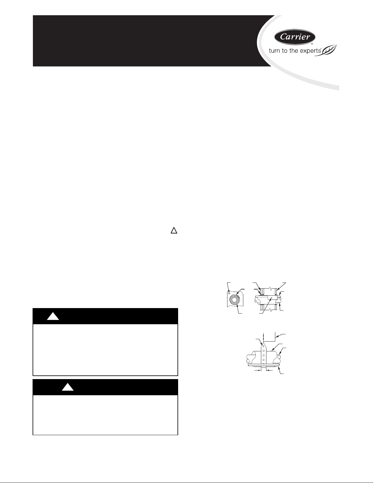
5. When passing refrigerant tubes through the wall, seal
opening with RTV or other pliable silicon--based caulk.
(See Fig. 1.)
6. Avoid direct tubing contact with water pipes, duct work,
floor joists, wall studs, floors, and walls.
7. Do not suspend refrigerant tubing from joists and studs with
a rigid wire or strap which comes in direct contact with
.
tubing.(See Fig. 1.)
8. Ensure that tubing insulation is pliable and completely
surrounds vapor tube.
9. When necessary, use hanger straps which are 1 in. wide and
conform to shape of tubing insulation. (See Fig. 1.)
10. Isolate hanger straps from insulation by using metal sleeves
bent to conform to shape of insulation.
OUTDOOR WALL INDOOR WALL
CAULK
INSULATION
HANGER STRAP
(AROUND SUCTION
TUBE ONLY)
1” (25.4 mm)
MIN
THROUGH THE WALL
SUSPENSION
LIQUID TUBE
SUCTION TUBE
JOIST
INSULATION
SUCTION TUBE
LIQUID TUBE
Fig. 1 -- Connecting Tubing Installation
When outdoor unit is connected to factory--approved indoor unit,
outdoor unit contains system refrigerant charge for operation with
AHRI rated indoor unit when connected by 15 ft. (4.57 m) of
field--supplied or factory accessory tubing. For proper unit
operation, check refrigerant charge using charging information
located on control box cover and/or in the Check Charge section of
this instruction.
IMPORTANT: Maximum liquid--line size is 3/8--in. OD for all
residential applications including line line.
A07588
IMPORTANT: Always install the factory--supplied liquid--line
filter drier. Obtain replacement filter driers from your distributor or
branch.
INSTALLATION
Check Equipment and Job Site
Unpack Unit
Move to final location. Remove carton taking care not to damage
unit.
Inspect Equipment
File claim with shipping company prior to installation if shipment
is damaged or incomplete. Locate unit rating plate on unit corner
panel. It contains information needed to properly install unit.
Check rating plate to be sure unit matches job specifications.
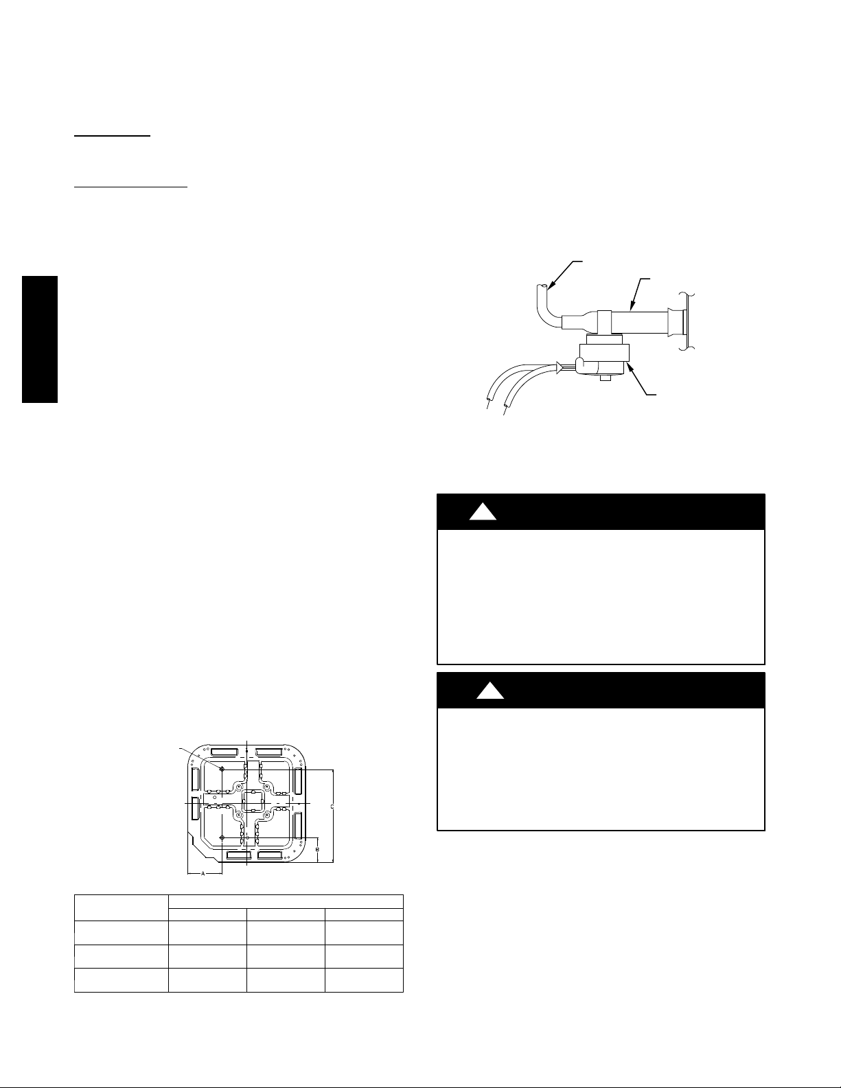
Install on a Solid, Level Mounting Pad
If conditions or local codes require the unit be attached to pad, tie
down bolts should be used and fastened through knockouts
provided in unit base pan. Refer to unit mounting pattern in Fig. 2
to determine base pan size and knockout hole location.
For hurricane tie downs, contact distributor for details and PE
Certification (Professional Engineer), if required.
On rooftop applications, mount on level platform or frame. Place
unit above a load--bearing wall and isolate unit and tubing set from
25HCB3 / 25HCC5
structure. Arrange supporting members to adequately support unit
and minimize transmission of vibration to building. Consult local
codes governing rooftop applications.
Roof mounted units exposed to winds above 5 mph (8.05 km/h)
may require wind baffles. Consult the Service Manual -Residential Split System Air Conditioners and Heat Pumps for
wind baffle construction.
NOTE: Unit must be level to within ±2° (±3/8 in./ft) per
compressor manufacturer specifications.
Clearance Requirements
When installing, allow sufficient space for airflow clearance,
wiring, refrigerant piping, and service. Allow 24 in. (609.6 mm)
clearance to service end of unit and 48 in. (1219.2 mm) (above
unit. For proper airflow, a 6--in. (152.4 mm) clearance on 1 side of
unit and 12--in. (304.8 mm) on all remaining sides must be
maintained. Maintain a distance of 24 in. (609.6 mm) between
units. Position so water, snow, or ice from roof or eaves cannot fall
directly on unit.
On rooftop applications, locate unit at least 6 in. (152.4 mm)
above roof surface.
Operating Ambient
The minimum outdoor operating ambient in cooling mode
without accessory is 55°F (12.78°C), and the maximum outdoor
operating ambient in cooling mode is 125°F (51.67°C). The
maximum outdoor operating ambient in heating mode is 66 °F
(18.89°C).
Check Defrost Thermostat
Check defrost thermostat to ensure it is properly located and
securely attached. There is a liquid header with a brass distributor
and feeder tube going into outdoor coil. At the end of the one of
the feeder tubes, there is a 3/8 in. O.D. stub tube approximately 2
in. long. (See Fig. 3.) The defrost thermostat should be located on
stub tube. Note that there is only one stub tube used with liquid
header, and on most units it is the bottom circuit.
FEEDER TUBE
STUB TUBE
DEFROST
THERMOSTAT
A97517
Fig. 3 -- Defrost Thermostat Location
Make Piping Connections
!
PERSONAL INJURY AND ENVIRONMENTAL
HAZARD
Failure to follow this warning could result in personal injury
or death.
Relieve pressure and recover all refrigerant before system
repair or final unit disposal.
Use all service ports and open all flow--control devices,
including solenoid valves.
!
WARNING
CAUTION
3/8--- in. (9.53 mm) Dia.
Tiedown Knock outs in
Basepan(2) Places
UNIT BASE PAN
Dimension in. (mm)
26 X 26
(660 X 660)
31–1/2 X 31–1/2
(800 X 800)
35 X 35
(889 X 889)
Fig. 2 -- Tiedown Knockout Locations
View From Top
TIEDOWN KNOCKOUT LOCATIONS in. (mm)
A B C
9–1/8 (231.8) 4–7/16 (112.7) 21–1/4 (539.8)
9–1/8 (231.8) 6–9/16 (166.7) 24–11/16 (627.1)
9–1/8 (231.8) 6–9/16 (166.7) 28–7/16 (722.3)
A05177
UNIT DAMAGE HAZARD
Failure to follow this caution may result in equipment damage
or improper operation.
If ANY refrigerant tubing is buried, provide a 6--in (152.4
mm). vertical rise at service valve. Refrigerant tubing lengths
up to 36--in (914.4 mm). may be buried without further special
consideration. Do not bury lines longer than 36 in (914.4 mm).
Outdoor units may be connected to indoor section using accessory
tubing package or field--supplied refrigerant gradetubing of correct
size and condition. For tubing requirements beyond 80 ft,
substantial capacity and performance losses can occur. Following
the recommendations in the Residential Piping and Long Line
Guideline will reduce these losses. Refer to Table 1 for accessory
requirements. Refer to Table 2 for field tubing diameters.
There are no buried--line applications greater than 36 in. (914.4
mm)
If refrigerant tubes or indoor coil are exposed to atmosphere, they
must be evacuated to 500 microns to eliminate contamination and
moisture in the system.
2
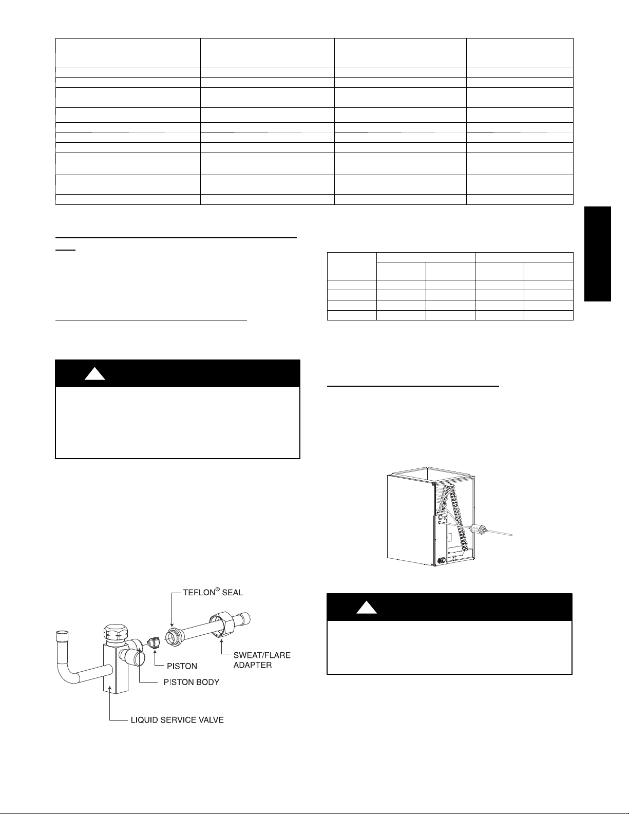
Table 1 – Accessory Usage
REQUIRED FOR LOW---AMBIENT
Accessory
Accumulator Standard Standard Standard
Ball Bearing Fan Motor Ye s { No No
Compressor Start Assist Capacitor and
Relay
Crankcase Heater Ye s
Evaporator Freeze Thermostat Ye s No No
Hard Shutoff TXV Ye s Ye s Yes
Isolation Relay Yes No No
Liquid Line Solenoid Valve No
Motor Master® Control or
Low Ambient Switch
Support Feet Recommended No Recommended
* For tubing line sets between 80 and 200 ft. (24.38 and 60.96 m) an d/or 20 ft. (6.09 m) vertical differential, refer to Residential Piping and Longline Guideline.
{ Additional requirement for Low ---Ambient Controller (full modulation feature) MotorMasterr Control.
Outdoor Unit Connected To Factory Approved Indoor
COOLING APPLICATIONS
(Below 55°F / 12.8°C)
Ye s Ye s No
Ye s No No
Table 2 – Refrigerant Connections and Recommended Liquid
Unit
Outdoor unit contains correct system refrigerant charge for
operation with approved ARI rated indoor unit when connected by
15 ft (4.57 m) of field--supplied or factory--accessory tubing, and
factory supplied filter drier. Check refrigerant charge for maximum
efficiency.
Refrigerant Tubing and Sweat Connections
Connect vapor tube to fitting on outdoor unit vapor service valves
(see Table 2). Connect liquid tubing to adapter tube on liquid
service valve. Use refrigerant grade tubing.
!
UNIT DAMAGE HAZARD
Failure to follow this caution may result in equipment
damage or improper operation.
Service valves must be wrapped in a heat--sinking material
such as a wet cloth while brazing.
CAUTION
UNIT SIZE
018, 024 3/8 3/8 5/8 5/8
030, 036 3/8 3/8 3/4 3/4
042, 048 3/8 3/8 7/8 7/8
060, 061 3/8 3/8 7/8 1--1/8
* Units are rated with 25 ft. (7.6 m) of lineset. See Product Data sheet for performance
data when using different size and length linesets.
Notes:
1. Do not apply capillary tube indoor coils to these units.
2. For Tubing Set lengths between 80 and 200 ft. (24.38 and 60.96 m) horizontal or
20 ft. (6.1 m) vertical di fferenti al, refer to the Residential Piping and Longline
Guideli ne using Puron ref rigerant .
Install Liquid Line Filter Drier Indoor
Refer to Fig. 5 and install filter drier as follows:
REQUIRED FOR
LONG LINE APPLICATIONS*
Ye s
See Long --- Line Application
Guideline
and Vapor Tube Diameters (In.)
Connection
LIQUID RATED VAPOR*
Diameter
Tub e
Diameter
1. Braze 5 in. (127 mm) liquid tube to the indoor coil.
2. Wrap filter drier with damp cloth.
3. Braze filter drier to 5 in. (127 mm) long liquid tube from
step 1.
REQUIRED FOR
SEA COAST APPLICATIONS
(Within 2 miles / 3.22 km)
No
No
Connection
Diameter
Tub e
Diameter
4. Connect and braze liquid refrigerant tube to the filter drier.
Remove plastic retainer holding outdoor piston in liquid service
valve, leaving the piston and piston retainer inside the valve.
Connect sweat/flare adapter provided, to valve. (See Fig. 4.)
Connect refrigerant tubing to fittings on outdoor unit vapor and
liquid service valves. Service valves are closed from factory and
ready for brazing. After wrapping service valve with a wet cloth,
tubing set can be brazed to service valve using either silver bearing
or non--silver bearing brazing material. Do not use soft solder
(materials which melt below 800°F/427°C). Consult local code
requirements. Refrigerant tubing and indoor coil are now ready for
leak testing. This check should include all field and factory joints.
A05227
Fig. 5 -- Liquid Line Filter Drier
25HCB3 / 25HCC5
Fig. 4 -- Liquid Service Valve
A05226
!
CAUTION
UNIT DAMAGE HAZARD
Failure to follow this caution may result in equipment damage
or improper operation.
Installation of filter drier in liquid line is required.
3
 Loading...