


COBRA™ Energy Recovery Units 48/50HJ004-014 with 62AQ060-300 Single-Package Rooftop Units with Energy Recovery Capability
Installation, Start-Up,
and Service Supplement
IMPORTANT: This is a supplemental instruction for the 48/50HJ and the 62AQ Installation, Start-Up and Service Instructions. It is not intended to take the place of either instruction or to be a complete piece in itself.
CONTENTS
Page
SAFETY CONSIDERATIONS . . . . . . . . . . . . . . . . . . . . . . 1
GENERAL . . . . . . . . . . . . . . . . . . . . . . . . . . . . . . . . . . . . . . . . 1
INSTALLATION . . . . . . . . . . . . . . . . . . . . . . . . . . . . . . . . 2-29
Step 1 — Inspect Shipment . . . . . . . . . . . . . . . . . . . . . . 2
Step 2 — Provide Unit Support . . . . . . . . . . . . . . . . . . . 2
• ROOF CURB
Step 3 — Field Fabricate Ductwork . . . . . . . . . . . . . . . 3
Step 4 — Rig and Place Unit . . . . . . . . . . . . . . . . . . . . . 6
•POSITIONING
Step 5 — Install Flue Hood (48HJ Only) . . . . . . . . . 11 Step 6 — Install Gas Piping (48HJ Only). . . . . . . . . 11
Step 7 — Install External Trap for Condensate Drain. . . . . . . . . . . . . . . . . . . . . . . . . . . . . . . . . . . . . . . . . . 11
Step 8 — Make Electrical Connections . . . . . . . . . . 11
•FIELD POWER SUPPLY
•FACTORY-SUPPLIED NON-FUSED DISCONNECT
•FIELD CONTROL WIRING
•HEAT ANTICIPATOR SETTINGS
Step 9 — Assemble and Mount
Supply-Air Hood . . . . . . . . . . . . . . . . . . . . . . . . . . . . . . 28
Step 10 — Mount the Barometric Relief Damper . . 28
Step 11 — Set the Outdoor Cooling and
Heating Thermostats. . . . . . . . . . . . . . . . . . . . . . . . . . 29
LIGHT COMMERCIAL THERMIDISTAT
ACCESSORY. . . . . . . . . . . . . . . . . . . . . . . . . . . . . . . 30-34
General. . . . . . . . . . . . . . . . . . . . . . . . . . . . . . . . . . . . . . . . . . 30
Power . . . . . . . . . . . . . . . . . . . . . . . . . . . . . . . . . . . . . . . . . . . 30
Dehumidification Equipment and Connections . . . 30
Step 1 — Select Light Commercial
Thermidistat Location . . . . . . . . . . . . . . . . . . . . . . . . . 30
Step 2 — Set DIP Switches. . . . . . . . . . . . . . . . . . . . . . . 30
Step 3 — Install Light Commercial Thermidistat . . 31
Step 4 — Set Light Commercial Thermidistat
Configuration. . . . . . . . . . . . . . . . . . . . . . . . . . . . . . . . . . 31
Step 5 — Conduct Light Commercial
Thermidistat Start-Up and Checkout . . . . . . . . . . . 33
Step 6 — Make Final Settings . . . . . . . . . . . . . . . . . . . . 34
OPERATIONAL INFORMATION . . . . . . . . . . . . . . . . . . 34
PRE-START-UP . . . . . . . . . . . . . . . . . . . . . . . . . . . . . . . . . . 35
START-UP . . . . . . . . . . . . . . . . . . . . . . . . . . . . . . . . . . . . . . . 35
SERVICE . . . . . . . . . . . . . . . . . . . . . . . . . . . . . . . . . . . . . 35-37
TROUBLESHOOTING . . . . . . . . . . . . . . . . . . . . . . . . . 38-41
ROOFTOP UNIT AND ENERGY$RECYCLER2
START-UP CHECKLIST . . . . . . . . . . . . . . . . CL-1, CL-2
SAFETY CONSIDERATIONS
Installation and servicing of air-conditioning equipment can be hazardous due to system pressure and electrical components. Only trained and qualified service personnel should install, repair, or service air-conditioning equipment.
Untrained personnel can perform basic maintenance functions of cleaning coils and filters and replacing filters. All other operations should be performed by trained service personnel. When working on air-conditioning equipment, observe precautions in the literature, tags and labels attached to the unit, and other safety precautions that apply.
Verify that the power source supplied to the unit matches the voltages and amperages listed on the unit rating plate.
Follow all safety codes. Wear safety glasses and work gloves. Use quenching cloth for unbrazing operations. Have fire extinguishers available for all brazing operations.
Disconnect gas piping from unit when leak testing at pressure greater than 1/2 psig. Pressures greater than 1/2 psig will cause gas valve damage resulting in hazardous condition. If gas valve is subjected to pressure greater than 1/2 psig, it must be replaced before use. When pressure testing fieldsupplied gas piping at pressures of 1/2 psig or less, a unit connected to such piping must be isolated by manually closing the gas valve.
Before performing service or maintenance operations on unit, turn off main power switch to unit and install a lockout tag. Electrical shock could cause personal injury.
GENERAL
Carrier’s factory-installed optional COBRA Energy Recovery units precondition ventilation air for the rooftop unit during winter and summer operation and recover energy from the building exhaust air. These units are designed to satisfy the higher ventilation requirements and other building codes while minimizing energy costs.
Factory installation of the energy recovery section provides the benefit of reduced field-installation time, single point power connections, and the assurance of a factory test for the complete COBRA Energy Recovery unit. The energy recovery section requires less maintenance than other energy recovery systems and can be serviced by any qualified refrigeration technician.
NOTE: Because of the location of the energy recovery section, the unit nameplate has been moved to the opposite end of the rooftop section, on the upper, right-hand part of the panel.
Manufacturer reserves the right to discontinue, or change at any time, specifications or designs without notice and without incurring obligations.
Book |
1 |
1 |
4 |
4 |
PC 111 Catalog No. 534-80122 |
Printed in U.S.A. |
Form 48/50HJ,62AQ-2SIS |
Pg 1 |
9-02 |
Replaces: 48/50HJ,62AQ-1SIS |
Tab |
1a |
1b |
6a |
6b |
|
|
|
|
|
|
|
|
|
|
|
|
|
|
|
|
|
INSTALLATION
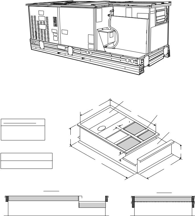
Step 1 — Inspect Shipment — File a claim with the shipping company if shipment is incomplete or damaged. See Fig. 1 for a typical shipping packaging for a COBRA™ energy recovery unit.
Step 2 — Provide Unit Support
ROOF CURB — The COBRA energy recovery unit can use a full-perimeter roof curb or a standard roof curb for the rooftop section of the unit with a supplemental equipment support for the
energy recovery section. The supplemental equipment support is not required. The standard rooftop unit roof curb is capable of supporting both the rooftop unit section and the energy recovery section. Assemble and install accessory roof curb in accordance with instructions shipped with curb. See Fig. 2A-4. Install insulation, cant strips, roofing felt, and counter flashing as shown.
Ductwork must be attached to curb, not to the unit. The accessory thru-the-bottom power and gas connection package must be installed before the unit is set on the roof curb.
Fig. 1 — Shipping Packaging (48/50HJ004-006 Shown)
|
Deck pans |
|
|
|
37 3/16" |
2" Return support. |
|
|
Only used on some |
||
|
67 3/8" |
||
|
applications. |
||
DUCT OPENING SIZES |
3 1/4 |
|
|
Supply = 13 7/8" x 20 1/4" |
R 1 |
|
|
|
Deck pans |
||
R1 = 13 5/8" x 17 3/4" |
|
||
|
R2 |
||
R2 = 13 5/8" x 12 5/16" |
14” |
||
|
|||
|
Supply |
|
|
|
|
14" |
|
R1 = Return from building to HVAC |
2" |
|
|
R2 = Return from building to 62AQ |
92 1/2" |
|
|
|
37 3/16" |
||
|
|
SIDE VIEW
END VIEW
Fig. 2A — COBRA Energy Recovery Unit Full-Perimeter Roof Curb — 48/50HJ004-007 with 62AQ060,100
2
|
Deck pans |
|
|
49 15/16" |
2" Return support. |
|
Only used on some |
|
|
|
|
|
78 1/4" |
applications. |
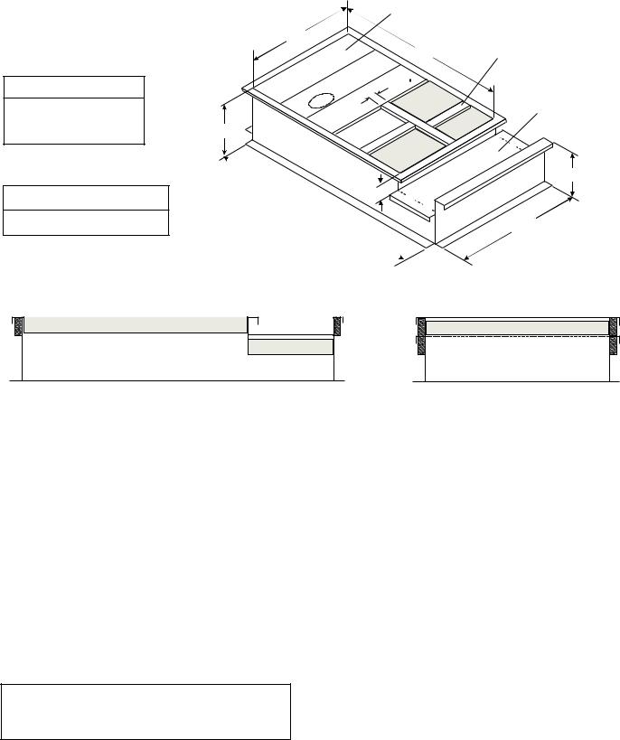
DUCT OPENING SIZES |
3 1/4 |
|
Supply = 15 11/16" x 31 3/8" |
R1 |
|
|
Deck pans |
|
R1 = 15 5/16" x 29 1/16" |
|
|
14" |
R 2 |
|
R2 = 15 5/16" x 9" |
|
|
|
Supply |
|
|
|
14" |
R1 = Return from building to HVAC |
2" |
|
110 11/16" |
|
|
|
|
|
R2 = Return from building to 62AQ |
|
49 15/16" |
|
|
SIDE VIEW
END VIEW
Fig. 2B — COBRA™ Energy Recovery Unit Full-Perimeter Roof Curb — 48/50HJ008-014 with 62AQ200,300
If electric control power or gas service is to be routed through the basepan, a field-installed accessory thru-the- bottom connection must be used. Attach the accessory to the basepan per the information in the accessory installation instructions. Thru-the-bottom connections must be installed before unit is set on roof.
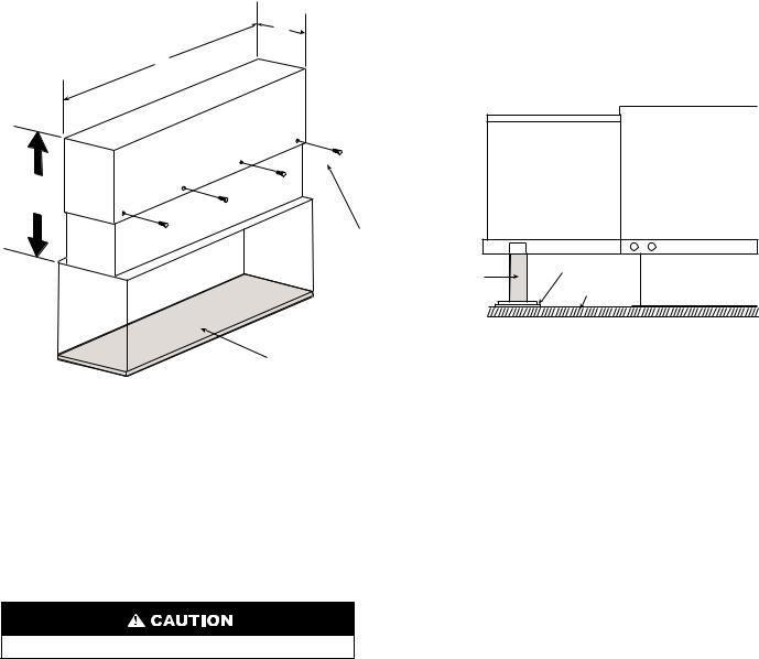
If the combined unit roof curb is not being used, additional support may be desired under the energy recovery section of the unit. An accessory support and pad for the energy recovery section can be used. See Fig. 4. Place the protective rubber pad on the roof so that the edge near the unit is located about 6-in. from the end of the energy recovery section. Measure the distance from the bottom of energy recovery rails to the pad. Adjust the energy recovery equipment support to match the measured distance and screw into place with the 4 screws provided. See Fig. 4. Place the support underneath the energy recovery unit and on the protective rubber pad. This is done by lifting the end of the energy recovery section slightly above level and then sliding the support underneath the rails.
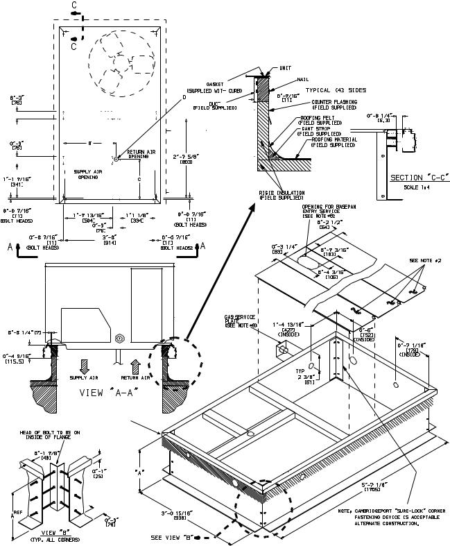
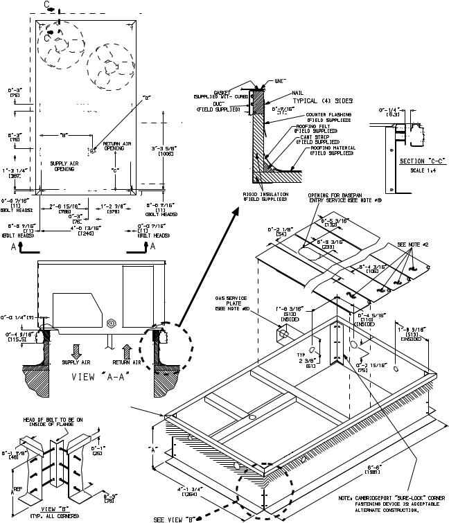
IMPORTANT: The gasketing of the unit to the roof curb is critical for a watertight seal. Install gasket supplied with the roof curb as shown in Fig. 3A and 3B. Improperly applied gasket can result in air leaks and poor unit performance.
Curb should be level. This is necessary for unit condensate drain to function properly. Refer to Accessory Roof Curb Installation Instructions for additional information as required.
Step 3 — Field Fabricate Ductwork — Secure all ducts to roof curb and building structure. Do not connect ductwork to unit. Insulate and weatherproof all external ductwork, joints, and roof openings with counter flashing and mastic in accordance with applicable codes. See Fig. 5A and 5B for duct dimensions.
Ducts passing through an unconditioned space must be insulated and covered with a vapor barrier. If a plenum return is used, the return should be ducted through the roof deck to comply with applicable fire codes.
A minimum clearance is not required around ductwork.
These units are designed for a minimum continuous heating return-air temperature of 50 F (dry bulb), or an intermittent operation down to 45 F (dry bulb), such as when used with a night set-back thermostat. To operate at lower return-air temperatures, a field-supplied outdoor-air temperature control must be used to initiate both stages of heat when the temperature is below 45 F. Indoor comfort may be compromised when these lower air temperatures are used with insufficient heating temperature rise.
3
CONNECTOR |
|
|
|
B |
|
|
C |
|
|
D ALT |
|
|
GAS |
|
|
|
|
POWER |
CONTROL |
|
||||||||||||||||||||||||||||||||||||
PKG. ACCY. |
|
|
|
|
|
DRAIN HOLE |
|
|
|
|
|
|
||||||||||||||||||||||||||||||||||||||||||||
|
|
|
|
|
|
|
|
|
|
|
|
|
|
|
|
|
|
|
|
|
|
|
|
|
|
|
|
|
|
|
|
|
|
|
|
|
|
|
|
|
||||||||||||||||
CRBTMPWR001A00 |
|
|
|
|
|
|
|
|
|
|
|
|
|
|
|
|
|
|
|
|
|
|
|
|
3/4″ |
|
3/4″ [19] NPT |
1/2″ |
||||||||||||||||||||||||||||
CRBTMPWR002A00 |
|
1′-911/16″ |
|
1′-4″ |
|
|
|
13/4″ |
[19] NPT |
|
|
11/4″ [31.7] |
[12.7] |
|
||||||||||||||||||||||||||||||||||||||||||
CRBTMPWR003A00 |
|
|
|
|
|
1 |
/2″ |
|
3/4″ [19] NPT |
|
|
|
|
|
||||||||||||||||||||||||||||||||||||||||||
|
[551] |
|
|
[406] |
[44.5] |
|
|
|
|
|
|
|
|
1/2″ |
||||||||||||||||||||||||||||||||||||||||||
|
|
|
|
|
|
|
|
|
|
|
|
|
[12.7] NPT |
|
|
|
|
|
|
|
|
|
|
|
|
|
||||||||||||||||||||||||||||||
CRBTMPWR004A00 |
|
|
|
|
|
|
|
|
|
|
|
|
|
|
|
|
|
|
|
|
|
|
3 |
/4″ |
|
|
11/4″ [31.7] |
[12.7] |
|
|||||||||||||||||||||||||||
|
|
|
|
|
|
|
|
|
|
|
|
|
|
|
|
|
|
|
|
|
|
|
|
|
|
|
|
|
|
|
|
|||||||||||||||||||||||||
|
|
|
|
|
|
|
|
|
|
|
|
|
|
|
|
|
|
|
|
|
|
|
|
|
|
|
|
[19] NPT |
|
|
|
|
|
|
|
|
|
|
|
|
|
|
|
|
|
|
||||||||||
|
|
|
|
|
|
|
|
|
|
|
|
|
|
|
|
|
|
|
|
|
|
|
|
|
|
|
|
|
|
|
|
|
|
|
|
|
|
|
|
|
|
|
|
|
|
|
|
|
|
|
|
|
|
|
|
|
|
|
|
|
|
|
|
|
|
|
|
|
|
|
|
|
|
|
|
|
|
|
|
|
|
|
|
|
|
|
|
|
|
|
|
|
|
|
|
|
|
|
|
|
|
|
|
|
|
|
|
|
|
|
|
|
|
|
|
|
|
|
|
|
|
|
|
|
|
|
|
|
|
|
|
|
|
|
|
|
|
|
|
|
|
|
|
|
|
|
|
|
|
|
|
|
|
|
|
|
|
|
|
|
|
|
|
|
|
|
|
|
|
|
|
|
|
|
|
|
|
|
|
|
|
|
|
|
|
|
|
|
|
|
|
|
|
|
|
|
|
|
|
|
|
|
|
|
|
|
|
|
|
|
|
|
|
|
|
|
|
|
|
|
|
|
|
|
|
|
|
|
|
|
|
|
|
|
|
|
|
|
|
|
|
|
|
|
|
|
|
|
|
|
|
|
|
|
|
|
|
|
|
|
|
|
|
|
|
|
|
|
|
|
|
|
|
|
|
|
|
|
|
|
|
|
|
|
|
|
|
|
|
|
|
|
|
|
|
|
|
|
|
|
|
|
|
|
|
|
|
|
|
|
|
|
|
|
|
|
|
|
|
|
|
|
|
|
|
|
|
|
|
|
|
|
|
|
|
|
|
|
|
|
|
|
|
|
|
|
|
|
|
|
|
|
|
|
|
|
|
|
|
|
|
|
|
|
|
|
|
|
|
|
|
|
|
|
|
|
|
|
|
|
|
|
|
|
|
|
|
|
|
|
|
|
|
|
|
|
|
|
|
|
|
|
|
|
|
|
|
|
|
|
|
|
|
|
|
|
|
|
|
|
|
|
|
|
|
|
|
|
|
|
|
|
|
|
|
|
|
|
|
|
|
|
|
|
|
|
|
|
|
|
|
|
|
|
|
|
|
|
|
|
|
|
|
|
|
|
|
|
|
|
|
|
|
|
|
|
|
|
|
|
|
|
|
|
|
|
|
|
|
|
|
|
|
|
|
|
|
|
|
|
|
|
|
|
|
|
|
|
|
|
|
|
|
|
|
|
|
|
|
|
|
|
|
|
|
|
|
|
|
|
|
|
|
|
|
|
|
|
|
|
|
|
|
|
|
|
|
|
|
|
|
|
|
|
|
|
|
|
|
|
|
|
|
|
|
|
|
|
|
|
|
|
|
|
|
|
|
|
|
|
|
|
|
|
|
|
|
|
|
|
|
|
|
|
|
|
|
|
|
|
|
|
|
|
|
|
|
|
|
|
|
|
|
|
|
|
|
|
|
|
|
|
|
|
|
|
|
|
|
|
|
|
|
|
|
|
|
|
|
|
|
|
|
|
|
|
|
|
|
|
|
|
|
|
|
|
|
|
|
|
|
|
|
|
|
|
|
|
|
|
|
|
|
|
|
|
|
|
|
|
|
|
|
|
|
|
|
|
|
|
|
|
|
|
|
|
|
|
|
|
|
|
|
|
|
|
|
|
|
|
|
|
|
|
|
|
|
|
|
|
|
|
|
|
|
|
|
|
|
|
|
|
|
|
|
|
|
|
|
|
|
|
|
|
|
|
|
|
|
|
|
|
|
|
|
|
|
|
|
|
|
|
|
|
|
|
|
|
|
|
|
|
|
|
|
|
|
|
|
|
|
|
|
|
|
|
|
|
|
|
|
|
|
|
|
|
|
|
|
|
|
|
|
|
|
|
|
|
|
|
|
|
|
|
|
|
|
|
|
|
|
|
|
|
|
|
|
|
|
|
|
|
|
|
|
|
|
|
|
|
|
|
|
|
|
|
|
|
|
|
|
|
|
|
|
|
|
|
|
|
|
|
|
|
|
|
|
|
|
|
|
|
|
|
|
|
|
|
|
|
|
|
|
|
|
|
|
|
|
|
|
|
|
|
|
|
|
|
|
|
|
|
|
|
|
|
|
|
|
|
|
|
|
|
|
|
|
|
|
|
|
|
|
|
|
|
|
|
|
|
|
|
|
|
|
|
|
|
|
|
|
|
|
|
|
|
|
|
|
|
|
|
|
|
|
|
|
|
|
|
|
|
|
|
|
|
|
|
|
|
|
|
|
|
|
|
|
|
|
|
|
|
|
|
|
|
|
|
|
|
|
|
|
|
|
|
|
|
|
|
|
|
|
|
|
|
|
|
|
|
|
|
|
|
|
|
|
|
|
|
|
|
|
|
|
|
|
|
|
|
|
|
|
|
|
|
|
|
|
|
|
|
|
|
|
|
|
|
|
|
|
|
|
|
|
|
|
|
|
|
|
|
|
|
|
|
|
|
|
|
|
|
|
|
|
|
|
|
|
|
|
|
|
|
|
|
|
|
|
|
|
|
|
|
|
|
|
|
|
|
|
|
|
|
|
|
|
|
|
|
|
|
|
|
|
|
|
|
|
|
|
|
|
|
|
|
|
|
|
|
|
|
|
|
|
|
|
|
|
|
|
|
|
|
|
|
|
|
|
|
|
|
|
|
|
|
|
|
|
|
|
|
|
|
|
|
|
|
|
|
|
|
|
|
|
|
|
|
|
|
|
|
|
|
|
|
|
|
|
|
|
|
|
|
|
|
|
|
|
|
|
|
|
|
|
|
|
|
|
|
|
|
|
|
|
|
|
|
|
|
|
|
|
|
|
|
|
|
|
|
|
|
|
|
|
|
|
|
|
|
|
|
|
|
|
|
|
|
|
|
|
|
|
|
|
|
|
|
|
|
|
|
|
|
|
|
|
|
|
|
|
|
|
|
|
|
|
|
|
|
|
|
|
|
|
|
|
|
|
|
|
|
|
|
|
|
|
|
|
|
|
|
|
|
|
|
|
|
|
|
|
|
|
|
|
|
|
|
|
|
|
|
|
|
|
|
|
|
|
|
|
|
|
|
|
|
|
|
|
|
|
|
|
|
|
|
|
|
|
|
|
|
|
|
|
|
|
|
|
|
|
|
|
|
|
|
|
|
|
|
|
|
|
|
|
|
|
|
|
|
|
|
|
|
|
|
|
|
|
|
|
|
|
|
|
|
|
|
|
|
|
|
|
|
|
|
|
|
|
|
|
|
|
|
|
|
|
|
|
|
|
|
|
|
|
|
|
|
|
|
|
|
|
|
|
|
|
|
|
|
|
|
|
|
|
|
|
|
|
|
|
|
|
|
|
|
|
|
|
|
|
|
|
|
|
|
|
|
|
|
|
|
|
|
|
|
|
|
|
|
|
|
|
|
|
|
|
|
|
|
|
|
|
|
|
|
|
|
|
|
|
|
|
|
|
|
|
|
|
|
|
|
|
|
|
|
|
|
|
|
|
|
|
|
|
|
|
|
|
|
|
|
|
|
|
|
|
|
|
|
|
|
|
|
|
|
|
|
|
|
|
|
|
|
|
|
|
|
|
|
|
|
|
|
|
|
|
|
|
|
|
|
|
|
|
|
|
|
|
|
|
|
|
|
|
|
|
|
|
|
|
|
|
|
|
|
|
|
|
|
|
|
|
|
|
|
|
|
|
|
|
|
|
|
|
|
|
|
|
|
|
|
|
|
|
|
|
|
|
|
|
|
|
|
|
|
|
|
|
|
|
|
|
|
|
|
|
|
|
|
|
|
|
|
|
|
|
|
|
|
|
|
|
|
|
|
|
|
|
|
|
|
|
|
|
|
|
|
|
|
|
|
|
|
|
|
|
|
|
|
|
|
|
|
|
|
|
|
|
|
|
|
|
|
|
|
|
|
|
|
|
|
|
|
|
|
|
|
|
|
|
|
|
|
|
|
|
|
|
|
|
|
|
|
|
|
|
|
|
|
|
|
|
|
|
|
|
|
|
|
|
|
|
|
|
|
|
|
|
|
|
|
|
|
|
|
|
|
|
|
|
|
|
|
|
|
|
|
|
|
|
|
|
|
|
|
|
|
|
|
|
|
|
|
|
|
|
|
|
|
|
|
|
|
|
|
|
|
|
|
|
|
|
|
|
|
|
|
|
|
|
|
|
|
|
|
|
|
|
|
|
|
|
|
|
|
|
|
|
|
|
|
|
|
|
|
|
|
|
|
|
|
|
|
|
|
|
|
|
|
|
|
|
|
|
|
|
|
|
|
|
|
|
|
|
|
|
|
|
|
|
|
|
|
|
|
|
|
|
|
|
|
|
|
|
|
|
|
|
|
|
|
|
|
|
|
|
|
|
|
|
|
|
|
|
|
|
|
|
|
|
|
|
|
|
|
|
|
|
|
|
|
|
|
|
|
|
ROOF CURB |
A |
UNIT SIZE |
|
ACCESSORY |
|||
|
|
||
CRRFCURB001A00 |
1′-2″ |
|
|
[356] |
48/50HJ |
||
|
|||
CRRFCURB002A00 |
2′-0″ |
004-007 |
|
[610] |
|
||
|
|
NOTES:
1.Roof curb accessory is shipped disassembled.
2.Insulated panels.
3. Dimensions in [ ] are in millimeters.
4.Roof curb: galvanized steel.
5.Attach ductwork to curb (flanges of duct rest on curb).
6.Service clearance: 4 ft on each side.
7. Direction of airflow.
8.Connector packages CRBTMPWR001A00 and 002A00 are for thru-the-curb type gas. Packages CRBTMPWR003A00 and 004A00 are for thru-the- bottom type gas connections.
TO ENSURE AIRTIGHT CONNECTION.
PLACE UNIT AS CLOSE TO THIS
END AS POSSIBLE
TO ENSURE AIRTIGHT CONNECTION.
PLACE UNIT AS CLOSE TO THIS
END AS POSSIBLE
Fig. 3A — Roof Curb Details (48/50HJ004-007 Section Only)
4
CONNECTOR |
|
|
|
|
|
|
|
|
|
|
|
|
|
|
|
|
|
|
|
|
|
|
|
|
|
|
|
D ALT |
|
|
|
|
|
|
|
|
|
|
|
|
|
|
|
|
|
|
|
|
|
|
|
|
|
||||||||||||
|
|
|
|
B |
|
|
|
|
|
|
C |
|
|
DRAIN |
|
|
|
GAS |
POWER |
|
|
|
CONTROL |
||||||||||||||||||||||||||||||||||||||||||
PKG. ACCY. |
|
|
|
|
|
|
|
|
|
|
|
|
|
|
|
|
|
|
|||||||||||||||||||||||||||||||||||||||||||||||
|
|
|
|
|
|
|
|
|
|
|
|
|
|
|
|
|
|
|
|
|
|
|
|
|
|
|
HOLE |
|
|
|
|
|
|
|
|
|
|
|
|
|
|
|
|
|
|
|
|
|
|
|
|
|
|||||||||||||
|
|
|
|
|
|
|
|
|
|
|
|
|
|
|
|
|
|
|
|
|
|
|
|
|
|
|
|
|
|
|
|
|
|
|
|
|
|
|
|
|
|
|
|
|
|
|
|
|
|
|
|
|
|
|
|
|
|
|
|
|
|
|
|
||
CRBTMPWR001A00 |
|
|
|
|
|
|
|
|
|
|
|
|
|
|
|
|
|
|
|
|
|
|
|
|
|
|
|
|
|
|
|
|
|
3/4″ |
3/4″ [19] NPT |
|
|
|
|
|
1/2″ |
||||||||||||||||||||||||
CRBTMPWR002A00 |
|
|
2′-87/16″ |
|
1′-1015/16″ |
|
|
|
|
13/4″ |
|
[19] NPT |
11/4″ [31.7] |
|
|
|
[12.7] NPT |
||||||||||||||||||||||||||||||||||||||||||||||||
CRBTMPWR003A00 |
|
|
|
|
|
|
|
1 |
/2″ |
3/4″ [19] NPT |
|
|
|
|
|
|
|
|
|
|
|||||||||||||||||||||||||||||||||||||||||||||
|
[827] |
|
|
|
|
[583] |
|
|
|
[44.5] |
|
|
|
|
|
|
|
|
|
|
|
1/2″ |
|||||||||||||||||||||||||||||||||||||||||||
|
|
|
|
|
|
|
|
|
|
|
|
|
|
|
|
|
|
|
|
[12.7] NPT |
|
|
|
|
|
|
|
|
|
|
|
|
|||||||||||||||||||||||||||||||||
CRBTMPWR004A00 |
|
|
|
|
|
|
|
|
|
|
|
|
|
|
|
|
|
|
|
|
|
|
|
|
|
|
|
|
|
3 |
/4″ |
11/4″ [31.7] |
|
|
|
[12.7] NPT |
|||||||||||||||||||||||||||||
|
|
|
|
|
|
|
|
|
|
|
|
|
|
|
|
|
|
|
|
|
|
|
|
|
|
|
|
|
|
|
|
|
|
|
|
|
|
|
|
|
|
|
|
|
|||||||||||||||||||||
|
|
|
|
|
|
|
|
|
|
|
|
|
|
|
|
|
|
|
|
|
|
|
|
|
|
|
|
|
|
|
|
|
|
|
|
|
|
|
|
|
|
[19] NPT |
|
|
|
|
|
|
|
|
|
|
|
|
|
|
|
|
|
||||||
|
|
|
|
|
|
|
|
|
|
|
|
|
|
|
|
|
|
|
|
|
|
|
|
|
|
|
|
|
|
|
|
|
|
|
|
|
|
|
|
|
|
|
|
|
|
|
|
|
|
|
|
|
|
|
|
|
|
|
|
|
|
|
|
|
|
|
|
|
|
|
|
|
|
|
|
|
|
|
|
|
|
|
|
|
|
|
|
|
|
|
|
|
|
|
|
|
|
|
|
|
|
|
|
|
|
|
|
|
|
|
|
|
|
|
|
|
|
|
|
|
|
|
|
|
|
|
|
|
|
|
|
|
|
|
|
|
|
|
|
|
|
|
|
|
|
|
|
|
|
|
|
|
|
|
|
|
|
|
|
|
|
|
|
|
|
|
|
|
|
|
|
|
|
|
|
|
|
|
|
|
|
|
|
|
|
|
|
|
|
|
|
|
|
|
|
|
|
|
|
|
|
|
|
|
|
|
|
|
|
|
|
|
|
|
|
|
|
|
|
|
|
|
|
|
|
|
|
|
|
|
|
|
|
|
|
|
|
|
|
|
|
|
|
|
|
|
|
|
|
|
|
|
|
|
|
|
|
|
|
|
|
|
|
|
|
|
|
|
|
|
|
|
|
|
|
|
|
|
|
|
|
|
|
|
|
|
|
|
|
|
|
|
|
|
|
|
|
|
|
|
|
|
|
|
|
|
|
|
|
|
|
|
|
|
|
|
|
|
|
|
|
|
|
|
|
|
|
|
|
|
|
|
|
|
|
|
|
|
|
|
|
|
|
|
|
|
|
|
|
|
|
|
|
|
|
|
|
|
|
|
|
|
|
|
|
|
|
|
|
|
|
|
|
|
|
|
|
|
|
|
|
|
|
|
|
|
|
|
|
|
|
|
|
|
|
|
|
|
|
|
|
|
|
|
|
|
|
|
|
|
|
|
|
|
|
|
|
|
|
|
|
|
|
|
|
|
|
|
|
|
|
|
|
|
|
|
|
|
|
|
|
|
|
|
|
|
|
|
|
|
|
|
|
|
|
|
|
|
|
|
|
|
|
|
|
|
|
|
|
|
|
|
|
|
|
|
|
|
|
|
|
|
|
|
|
|
|
|
|
|
|
|
|
|
|
|
|
|
|
|
|
|
|
|
|
|
|
|
|
|
|
|
|
|
|
|
|
|
|
|
|
|
|
|
|
|
|
|
|
|
|
|
|
|
|
|
|
|
|
|
|
|
|
|
|
|
|
|
|
|
|
|
|
|
|
|
|
|
|
|
|
|
|
|
|
|
|
|
|
|
|
|
|
|
|
|
|
|
|
|
|
|
|
|
|
|
|
|
|
|
|
|
|
|
|
|
|
|
|
|
|
|
|
|
|
|
|
|
|
|
|
|
|
|
|
|
|
|
|
|
|
|
|
|
|
|
|
|
|
|
|
|
|
|
|
|
|
|
|
|
|
|
|
|
|
|
|
|
|
|
|
|
|
|
|
|
|
|
|
|
|
|
|
|
|
|
|
|
|
|
|
|
|
|
|
|
|
|
|
|
|
|
|
|
|
|
|
|
|
|
|
|
|
|
|
|
|
|
|
|
|
|
|
|
|
|
|
|
|
|
|
|
|
|
|
|
|
|
|
|
|
|
|
|
|
|
|
|
|
|
|
|
|
|
|
|
|
|
|
|
|
|
|
|
|
|
|
|
|
|
|
|
|
|
|
|
|
|
|
|
|
|
|
|
|
|
|
|
|
|
|
|
|
|
|
|
|
|
|
|
|
|
|
|
|
|
|
|
|
|
|
|
|
|
|
|
|
|
|
|
|
|
|
|
|
|
|
|
|
|
|
|
|
|
|
|
|
|
|
|
|
|
|
|
|
|
|
|
|
|
|
|
|
|
|
|
|
|
|
|
|
|
|
|
|
|
|
|
|
|
|
|
|
|
|
|
|
|
|
|
|
|
|
|
|
|
|
|
|
|
|
|
|
|
|
|
|
|
|
|
|
|
|
|
|
|
|
|
|
|
|
|
|
|
|
|
|
|
|
|
|
|
|
|
|
|
|
|
|
|
|
|
|
|
|
|
|
|
|
|
|
|
|
|
|
|
|
|
|
|
|
|
|
|
|
|
|
|
|
|
|
|
|
|
|
|
|
|
|
|
|
|
|
|
|
|
|
|
|
|
|
|
|
|
|
|
|
|
|
|
|
|
|
|
|
|
|
|
|
|
|
|
|
|
|
|
|
|
|
|
|
|
|
|
|
|
|
|
|
|
|
|
|
|
|
|
|
|
|
|
|
|
|
|
|
|
|
|
|
|
|
|
|
|
|
|
|
|
|
|
|
|
|
|
|
|
|
|
|
|
|
|
|
|
|
|
|
|
|
|
|
|
|
|
|
|
|
|
|
|
|
|
|
|
|
|
|
|
|
|
|
|
|
|
|
|
|
|
|
|
|
|
|
|
|
|
|
|
|
|
|
|
|
|
|
|
|
|
|
|
|
|
|
|
|
|
|
|
|
|
|
|
|
|
|
|
|
|
|
|
|
|
|
|
|
|
|
|
|
|
|
|
|
|
|
|
|
|
|
|
|
|
|
|
|
|
|
|
|
|
|
|
|
|
|
|
|
|
|
|
|
|
|
|
|
|
|
|
|
|
|
|
|
|
|
|
|
|
|
|
|
|
|
|
|
|
|
|
|
|
|
|
|
|
|
|
|
|
|
|
|
|
|
|
|
|
|
|
|
|
|
|
|
|
|
|
|
|
|
|
|
|
|
|
|
|
|
|
|
|
|
|
|
|
|
|
|
|
|
|
|
|
|
|
|
|
|
|
|
|
|
|
|
|
|
|
|
|
|
|
|
|
|
|
|
|
|
|
|
|
|
|
|
|
|
|
|
|
|
|
|
|
|
|
|
|
|
|
|
|
|
|
|
|
|
|
|
|
|
|
|
|
|
|
|
|
|
|
|
|
|
|
|
|
|
|
|
|
|
|
|
|
|
|
|
|
|
|
|
|
|
|
|
|
|
|
|
|
|
|
|
|
|
|
|
|
|
|
|
|
|
|
|
|
|
|
|
|
|
|
|
|
|
|
|
|
|
|
|
|
|
|
|
|
|
|
|
|
|
|
|
|
|
|
|
|
|
|
|
|
|
|
|
|
|
|
|
|
|
|
|
|
|
|
|
|
|
|
|
|
|
|
|
|
|
|
|
|
|
|
|
|
|
|
|
|
|
|
|
|
|
|
|
|
|
|
|
|
|
|
|
|
|
|
|
|
|
|
|
|
|
|
|
|
|
|
|
|
|
|
|
|
|
|
|
|
|
|
|
|
|
|
|
|
|
|
|
|
|
|
|
|
|
|
|
|
|
|
|
|
|
|
|
|
|
|
|
|
|
|
|
|
|
|
|
|
|
|
|
|
|
|
|
|
|
|
|
|
|
|
|
|
|
|
|
|
|
|
|
|
|
|
|
|
|
|
|
|
|
|
|
|
|
|
|
|
|
|
|
|
|
|
|
|
|
|
|
|
|
|
|
|
|
|
|
|
|
|
|
|
|
|
|
|
|
|
|
|
|
|
|
|
|
|
|
|
|
|
|
|
|
|
|
|
|
|
|
|
|
|
|
|
|
|
|
|
|
|
|
|
|
|
|
|
|
|
|
|
|
|
|
|
|
|
|
|
|
|
|
|
|
|
|
|
|
|
|
|
|
|
|
|
|
|
|
|
|
|
|
|
|
|
|
|
|
|
|
|
|
|
|
|
|
|
|
|
|
|
|
|
|
|
|
|
|
|
|
|
|
|
|
|
|
|
|
|
|
|
|
|
|
|
|
|
|
|
|
|
|
|
|
|
|
|
|
|
|
|
|
|
|
|
|
|
|
|
|
|
|
|
|
|
|
|
|
|
|
|
|
|
|
|
|
|
|
|
|
|
|
|
|
|
|
|
|
|
|
|
|
|
|
|
|
|
|
|
|
|
|
|
|
|
|
|
|
|
|
|
|
|
|
|
|
|
|
|
|
|
|
|
|
|
|
|
|
|
|
|
|
|
|
|
|
|
|
|
|
|
|
|
|
|
|
|
|
|
|
|
|
|
|
|
|
|
|
|
|
|
|
|
|
|
|
|
|
|
|
|
|
|
|
|
|
|
|
|
|
|
|
|
|
|
|
|
|
|
|
|
|
|
|
|
|
|
|
|
|
|
|
|
|
|
|
|
|
|
|
|
|
|
|
|
|
|
|
|
|
|
|
|
|
|
|
|
|
|
|
|
|
|
|
|
|
|
|
|
|
|
|
|
|
|
|
|
|
|
|
|
|
|
|
|
|
|
|
|
|
|
|
|
|
|
|
|
|
|
|
|
|
|
|
|
|
|
|
|
|
|
|
|
|
|
|
|
|
|
|
|
|
|
|
|
|
|
|
|
|
|
|
|
|
|
|
|
|
|
|
|
|
|
|
|
|
|
|
|
|
|
|
|
|
|
|
|
|
|
|
|
|
|
|
|
|
|
|
|
|
|
|
|
|
|
|
|
|
|
|
|
|
|
|
|
|
|
|
|
|
|
|
|
|
|
|
|
|
|
|
|
|
|
|
|
|
|
|
|
|
|
|
|
|
|
|
|
|
|
|
|
|
|
|
|
|
|
|
|
|
|
|
|
|
|
|
|
|
|
|
|
|
|
|
|
|
|
|
|
|
|
|
|
|
|
|
|
|
|
|
|
|
|
|
|
|
|
|
|
|
|
|
|
|
|
|
|
|
|
|
|
|
|
|
|
|
|
|
|
|
|
|
|
|
|
|
|
|
|
|
|
|
|
|
|
|
|
|
|
|
|
|
|
|
|
|
|
|
|
|
|
|
|
|
|
|
|
|
|
|
|
|
|
|
|
|
|
|
|
|
|
|
|
|
|
|
|
|
|
|
|
|
|
|
|
|
|
|
|
|
|
|
|
|
|
|
|
|
|
|
|
|
|
|
|
|
|
|
|
|
|
|
|
|
|
|
|
|
|
|
|
|
|
|
|
|
|
|
|
|
|
|
|
|
|
|
|
|
|
|
|
|
|
|
|
|
ROOF CURB |
“A” |
UNIT SIZE |
|
ACCESSORY |
48/50HJ |
||
|
|||
CRRFCURB003A00 |
1′-2″ [356] |
008-014 |
|
CRRFCURB004A00 |
2′-0″ [610] |
||
|
NOTES:
1.Roof curb accessory is shipped disassembled.
2.Insulated panels: 1-in. thick polyurethane foam,
13/4 lb density.
3. Dimensions in [ ] are in millimeters.
4.Roof curb: 16-gage steel.
5.Attach ductwork to curb (flanges of duct rest on curb).
6.Service clearance 4 ft on each side.
7. Direction of airflow.
8.Connector packages CRBTMPWR001A00 and 2A00 are for thru-the-curb gas type. Packages CRBTMPWR003A00 and 4A00 are for thru- the-bottom type gas connections.
TO ENSURE AN AIRTIGHT CONNECTION,
PLACE UNIT ON CURB AS CLOSE TO
DUCT END AS POSSIBLE.
TO ENSURE AN AIRTIGHT CONNECTION,
PLACE UNIT ON CURB AS CLOSE TO
DUCT END AS POSSIBLE.
Fig. 3B — Roof Curb Details (48/50HJ008-014 Section Only)
5
|
UNIT SIZE |
EQUIPMENT SUPPORT |
DIMENSIONS (in.) |
|
|||||
4” |
PART NUMBER |
A |
B |
C |
|
||||
|
|
||||||||
3-6 Ton |
CRAQSUPT001A00 |
36.9 |
40 |
8 to 14 |
|
||||
|
|||||||||
A |
CRAQSUPT002A00 |
36.9 |
40 |
14 to 24 |
|
||||
|
|
||||||||
|
|
CRAQSUPT003A00 |
49.7 |
54 |
8 to 14 |
|
|||
71/2-121/2 |
Ton |
||||||||
CRAQSUPT004A00 |
49.7 |
54 |
14 to 24 |
||||||
|
|
|
|||||||
|
|
|
|
|
|
|
|
|
|
|
|
ENERGY |
HVAC UNIT |
|
|
RECOVERY |
|
C” |
|
SECTION |
|
|
|
|
|
|
SCREW |
|
|
|
SUPPORT |
|
|
|
IN PLACE |
PAD |
|
|
ADJUSTABLE |
CURB |
|
|
|
||
|
EQUIPMENT |
|
|
|
ROOF |
|
|
|
SUPPORT |
|
|
|
|
|
10” x B (SEE CHART) PROTECTIVE RUBBER PAD (EPDM)
Fig. 4 — Supplemental Energy Recovery Section Equipment Support
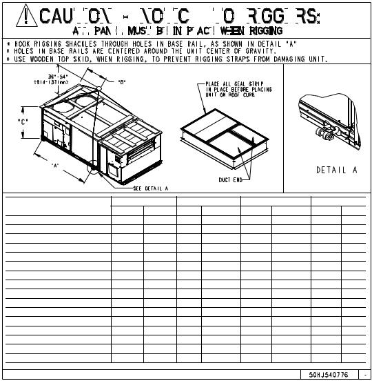
Step 4 — Rig and Place Unit — Keep unit upright and do not drop. Spreader bars are not required if top crating is left on unit. Rollers may be used to move unit across a roof. Remove the bottom wooden skids that are under the unit by removing the wooden plates that hold the bottom wooden frame to the unit. Level by using unit frame as a reference. Lifting holes are provided in base rails as shown in Fig. 6A and 6B. Refer to rigging instructions on unit.
All panels must be in place when rigging.
POSITIONING — Maintain clearance around and above unit to provide minimum distance from combustible materials, proper airflow, and service access. A properly positioned unit will have the following clearances between unit and roof curb: 1/4-in. clearance between roof curb and base rails on each side and duct end of unit; 1/4-in. clearance between roof curb and condenser coil end of unit.
Do not install unit in an indoor location. Do not locate unit air inlets near exhaust vents or other sources of contaminated air.
Be sure that unit is installed such that snow will not block the combustion intake or flue outlet.
Unit may be installed directly on wood flooring or on Class A, B, or C roof-covering material when roof curb is used.
Although unit is weatherproof, guard against water from higher level runoff and overhangs.
Flue vent discharge must have a minimum horizontal clearance of 4 ft from electric and gas meters, gas regulators, and gas relief equipment.
Minimum distance between unit and other electrically live parts is 48 inches.
Flue gas can deteriorate building materials. Orient unit such that flue gas will not affect building materials. Locate mechanical draft system flue assembly at least 48 in. from an adjacent building or combustible material.
Adequate combustionand ventilation-air space must be provided for proper operation of this equipment. Be sure that installation complies with all local codes and Section 5.3, Air for Combustion and Ventilation, NFGC (National Fuel Gas Code), and ANSI (American National Standards Institute) Z223.1, and NFPA (National Fire Protection Association) 54 TIA-54-84-1. In Canada, installation must be in accordance with the CAN1-B149 installation codes for gas burning appliances.
After unit is in position, remove rigging skids and shipping materials.
6
REAR
|
RIGHT |
LEFT |
SIDE |
SIDE |
|
7
FRONT
RIGHT SIDE
LEFT SIDE |
FRONT |
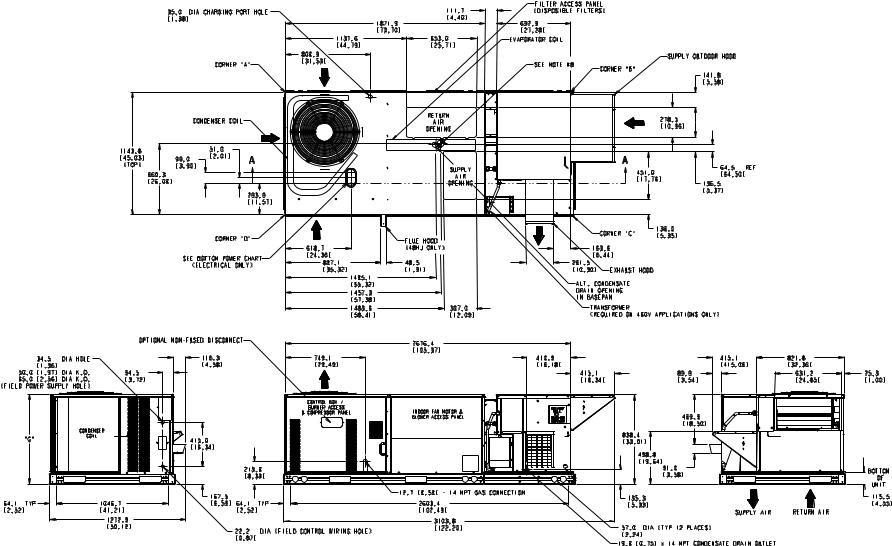
Fig. 5A — Base Unit Dimensions — COBRA™ Energy Recovery Unit — 48/50HJ004-007 with 62AQ060,100

8
Fig. 5A — Base Unit Dimensions — COBRA™ Energy Recovery Unit — 48/50HJ004-007 with 62AQ060,100 (cont)
9
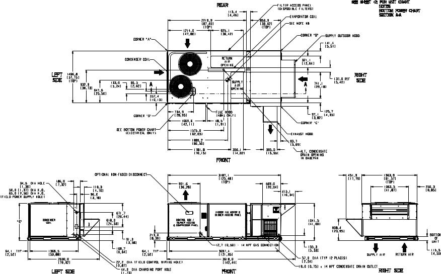
Fig. 5B — Base Unit Dimensions — COBRA™ Energy Recovery Unit — 48/50HJ008-014 with 62AQ200,300
10
Fig. 5B — Base Unit Dimensions — COBRA™ Energy Recovery Unit — 48/50HJ008-014 with 62AQ200,300 (cont)
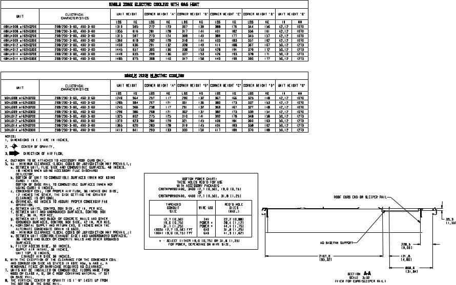
|
|
MAX WEIGHT |
|
A |
|
B |
|
|
C |
||
|
|
lb |
kg |
in. |
mm |
in |
|
mm |
in. |
|
mm |
48HJ004 w/62AQ060 |
890 |
404 |
95.6 |
2428.20 |
57.38 |
|
1457.30 |
33.35 |
|
847 |
|
48HJ004 w/62AQ100 |
905 |
411 |
95.6 |
2428.20 |
57.38 |
|
1457.30 |
33.35 |
|
847 |
|
48HJ005 w/62AQ060 |
900 |
409 |
95.6 |
2428.20 |
57.38 |
|
1457.30 |
33.35 |
|
847 |
|
48HJ005 w/62AQ100 |
915 |
415 |
95.6 |
2428.20 |
57.38 |
|
1457.30 |
33.35 |
|
847 |
|
48HJ006 w/62AQ060 |
920 |
418 |
95.6 |
2428.20 |
57.38 |
|
1457.30 |
33.35 |
|
847 |
|
48HJ006 w/62AQ100 |
935 |
425 |
95.6 |
2428.20 |
57.38 |
|
1457.30 |
33.35 |
|
847 |
|
48HJ007 w/62AQ060 |
995 |
452 |
95.6 |
2428.20 |
57.38 |
|
1457.30 |
42.12 |
|
1070 |
|
48HJ007 w/62AQ100 |
1010 |
459 |
95.6 |
2428.20 |
57.38 |
|
1457.30 |
42.12 |
|
1070 |
|
50HJ004 w/62AQ060 |
795 |
361 |
95.6 |
2428.20 |
57.38 |
|
1457.30 |
33.35 |
|
847 |
|
50HJ004 w/62AQ100 |
810 |
368 |
95.6 |
2428.20 |
57.38 |
|
1457.30 |
33.35 |
|
847 |
|
50HJ005 w/62AQ060 |
805 |
365 |
95.6 |
2428.20 |
57.38 |
|
1457.30 |
33.35 |
|
847 |
|
50HJ005 w/62AQ100 |
820 |
372 |
95.6 |
2428.20 |
57.38 |
|
1457.30 |
33.35 |
|
847 |
|
50HJ006 w/62AQ060 |
825 |
375 |
95.6 |
2428.20 |
57.38 |
|
1457.30 |
33.35 |
|
847 |
|
50HJ006 w/62AQ100 |
840 |
381 |
95.6 |
2428.20 |
57.38 |
|
1457.30 |
33.35 |
|
847 |
|
50HJ007 w/62AQ060 |
880 |
400 |
95.6 |
2428.20 |
57.38 |
|
1457.30 |
42.12 |
|
1070 |
|
50HJ007 w/62AQ100 |
895 |
407 |
95.6 |
2428.20 |
57.38 |
|
1457.30 |
42.12 |
|
1070 |
|
Fig. 6A — Rigging Label — COBRA™ Energy Recovery Unit — Sizes 48/50HJ004-007
Step 5 — Install Flue Hood (48HJ Rooftop Sections Only) — Refer to the 48HJ installation instructions for information on installing the flue hood.
Step 6 — Install Gas Piping (48HJ Rooftop Sections Only) — Refer to the 48HJ installation instructions for information on installing the gas piping.
Step 7 — Install External Trap For Condensate Drain — The condensate from the rooftop unit along with condensate from the upper coil of the energy recovery section is internally piped to the condensate pan in the lower section of the energy recovery section. For this reason, the bottom drain on the rooftop unit CANNOT be used for a condensate drain. The 3/4-in. drain connection on the energy recovery section is located near the bottom left of the exhaust air section. See Fig. 5A and 5B. The energy recovery section must have a field-fabricated, external, P-trap installed for condensate drainage. Trap must be at least 4-in. deep to protect against freezeup. If the drain line is installed downstream from the external
trap, pitch the line away from the unit at 1-in. per 10-ft of run. Do not use a pipe smaller than the connection (3/4-in.).
Step 8 — Make Electrical Connections
Unit cabinet must have an uninterrupted, unbroken electrical ground to minimize the possibility of personal injury if an electrical fault should occur. This ground may consist of electrical wire connected to unit ground lug in control compartment, or conduit approved for electrical ground when installed in accordance with NEC (National Electrical Code), ANSI/NFPA, latest edition, and local electrical codes. Do not use gas piping as an electrical ground. Failure to follow this warning could result in the installer being liable for personal injury of others.
FIELD POWER SUPPLY — All units except 208/230-v units are factory wired for the voltage shown on the nameplate.
11
|
|
|
|
|
|
|
|
|
|
|
|
|
|
|
|
|
|
|
|
|
|
|
|
|
|
|
|
|
|
|
|
|
|
|
|
|
|
|
|
|
|
|
|
|
|
|
|
|
|
|
|
|
|
|
|
|
|
|
|
|
|
|
|
|
|
|
|
|
|
|
|
|
|
|
|
|
|
|
|
|
|
|
|
|
|
|
|
|
|
|
|
|
|
|
|
|
|
|
|
|
|
|
|
|
|
|
|
|
|
|
|
|
|
|
|
|
|
|
|
|
|
|
|
|
|
|
|
|
|
|
|
|
|
|
|
|
|
|
|
|
|
|
|
|
|
|
|
|
|
|
|
|
|
|
|
|
|
|
|
|
|
|
|
|
|
|
|
|
|
|
|
|
|
|
|
|
|
|
|
|
|
|
|
|
|
|
|
|
|
|
|
|
|
|
|
|
|
|
|
|
|
|
|
|
|
|
|
|
|
|
|
|
|
|
|
|
|
|
|
|
|
|
|
|
|
|
|
|
|
|
|
|
|
|
|
|
|
|
|
|
|
|
|
|
|
|
|
|
|
|
|
|
|
|
MAX WEIGHT |
|
|
|
|
|
A |
|
|
|
B |
|
C |
||||||||||||||||||||
|
|
|
|
|
|
|
|
|
|
|
|
|
|
|
|
lb |
|
|
kg |
|
|
in. |
|
|
|
|
|
mm |
|
in. |
|
mm |
in. |
mm |
|||||||||||||
48HJ008 w/62AQ200 |
1310 |
|
595 |
77.42 |
1966.5 |
66.50 |
1689.10 |
42.12 |
1070 |
||||||||||||||||||||||||||||||||||||||
48HJ008 w/62AQ300 |
1355 |
|
616 |
77.42 |
1966.5 |
66.50 |
1689.10 |
42.12 |
1070 |
||||||||||||||||||||||||||||||||||||||
48HJ009 w/62AQ200 |
1315 |
|
597 |
77.42 |
1966.5 |
66.50 |
1689.10 |
42.12 |
1070 |
||||||||||||||||||||||||||||||||||||||
48HJ009 w/62AQ300 |
1360 |
|
618 |
77.42 |
1966.5 |
66.50 |
1689.10 |
42.12 |
1070 |
||||||||||||||||||||||||||||||||||||||
48HJ012 w/62AQ200 |
1400 |
|
636 |
77.42 |
1966.5 |
66.50 |
1689.10 |
50.12 |
1273 |
||||||||||||||||||||||||||||||||||||||
48HJ012 w/62AQ300 |
1445 |
|
657 |
77.42 |
1966.5 |
66.50 |
1689.10 |
50.12 |
1273 |
||||||||||||||||||||||||||||||||||||||
48HJ014 w/62AQ200 |
1440 |
|
655 |
77.42 |
1966.5 |
66.50 |
1689.10 |
50.12 |
1273 |
||||||||||||||||||||||||||||||||||||||
48HJ014 w/62AQ300 |
1485 |
|
675 |
77.42 |
1966.5 |
66.50 |
1689.10 |
50.12 |
1273 |
||||||||||||||||||||||||||||||||||||||
50HJ008 w/62AQ200 |
1240 |
|
564 |
77.42 |
1966.5 |
66.50 |
1689.10 |
42.12 |
1070 |
||||||||||||||||||||||||||||||||||||||
50HJ008 w/62AQ300 |
1285 |
|
584 |
77.42 |
1966.5 |
66.50 |
1689.10 |
42.12 |
1070 |
||||||||||||||||||||||||||||||||||||||
50HJ009 w/62AQ200 |
1245 |
|
566 |
77.42 |
1966.5 |
66.50 |
1689.10 |
42.12 |
1070 |
||||||||||||||||||||||||||||||||||||||
50HJ009 w/62AQ300 |
1290 |
|
586 |
77.42 |
1966.5 |
66.50 |
1689.10 |
42.12 |
1070 |
||||||||||||||||||||||||||||||||||||||
50HJ012 w/62AQ200 |
1325 |
|
602 |
77.42 |
1966.5 |
66.50 |
1689.10 |
42.12 |
1070 |
||||||||||||||||||||||||||||||||||||||
50HJ012 w/62AQ300 |
1370 |
|
623 |
77.42 |
1966.5 |
66.50 |
1689.10 |
42.12 |
1070 |
||||||||||||||||||||||||||||||||||||||
50HJ014 w/62AQ200 |
1345 |
|
620 |
77.42 |
1966.5 |
66.50 |
1689.10 |
42.12 |
1070 |
||||||||||||||||||||||||||||||||||||||
50HJ014 w/62AQ300 |
1410 |
|
641 |
77.42 |
1966.5 |
66.50 |
1689.10 |
42.12 |
1070 |
||||||||||||||||||||||||||||||||||||||
Fig. 6B — Rigging Label — COBRA™ Energy Recovery Unit — Sizes 48/50HJ008-014
If the 208/230-v unit is to be connected to a 208-v power supply, the transformer must be rewired by moving the black wire with the 1/4-in. female space connector from the 230-volt connection and moving to the 200-volt 1/4-in. male terminal on the primary side of the transformer.
Refer to unit label diagram for additional information. Pigtails are provided for field wire connections. Use factorysupplied splices or UL (Underwriters’ Laboratories) approved copper/aluminum connector.
When installing units, provide a disconnect per the NEC.
All field wiring must comply with NEC and local requirements.
Install field wiring as follows:
1.Install conduit through side panel openings. Install conduit between disconnect and control box.
2.Install power lines to terminal connections as shown in Fig. 7.
Voltage to compressor terminals during operation must be within voltage range indicated on unit nameplate (see Tables 1A-1H). On 3-phase units, voltages between phases must be balanced within 2% and the current within 10%. Use the formula shown in the legend for Tables 1A-1H, Note 2 to determine the percent of voltage imbalance. Operation on improper line voltage or excessive phase imbalance constitutes abuse and
may cause damage to electrical components. Such operation would invalidate any applicable Carrier warranty.
FACTORY-SUPPLIED NON-FUSED DISCONNECT — The factory-supplied disconnect is capable of handling disconnect amps up to 80 A for a COBRA Energy Recovery unit. For disconnect amps greater than 80 A, a field-supplied disconnect is required.
FIELD CONTROL WIRING — Install a Carrier-approved accessory thermidistat assembly according to installation instructions included with the accessory. Locate thermidistat assembly on a solid wall in the conditioned space to sense average temperature in accordance with thermidistat installation instructions on page 30. Connect thermidistat wires to terminal board.
Route thermidistat cable or equivalent single leads of colored wire from subbase terminals through connector on unit to low-voltage connections (shown in Fig. 8). Thermidistat control wiring is routed to both the rooftop unit control box and the energy recovery section control box.
If a PremierLink™ control is used, a thermidistat does not need to be used. A humidistat and a separate room air sensor are used. Two extra terminal blocks (TB2 and TB3) are provided in the control box for all units with PremierLink controls. No wiring should be directly connected to the PremierLink control. Wire sensors to TB2 or TB3. Humidistat is wired to TB1 and energy recovery section control box.
12
NOTE: For wire runs up 50 ft, use no. 18 AWG (American Wire Gage) insulated wire (35 C minimum). For 50 to 75 ft, use no. 16 AWG insulated wire (35 C minimum). For over 75 ft, use no. 14 AWG insulated wire (35 C minimum). All wire larger than no. 18 AWG cannot be directly connected to the thermostat and will require a junction box and splice at the thermostat.
Pass the control wires through the hole provided in the corner post; then feed wires through the raceway built into the corner post to the 24-v barrier located on the left side of the
control box. See Fig. 10. The raceway provides the UL required clearance between highand low-voltage wiring.
NOTE: A humidistat and a temperature sensor can be used in place of a thermidistat for PremierLink™ units.
HEAT ANTICIPATOR SETTINGS — Set heat anticipator settings at .14 amp for the first stage and .14 amp for secondstage heating, when available.
Table 1A — Electrical Data (COBRA™ Energy Recovery 48HJ004-007 Units with 62AQ060)
|
NOMINAL |
IFM |
CONV |
62AQ |
POWER SUPPLY |
DISCONNECT SIZE* |
||
UNIT |
V-PH-Hz |
TYPE |
OUTLET |
FLA |
MCA |
FUSE OR |
FLA |
LRA |
|
HACR BKR |
|||||||
|
|
|
|
|
|
|
|
|
|
208/230-1-60 |
STD |
NO |
9.2 |
34.8/34.8 |
40/40 |
35/35 |
135/135 |
|
STD |
YES |
9.2 |
40.8/40.8 |
45/45 |
41/41 |
140/140 |
|
|
|
|||||||
|
|
STD |
NO |
9.2 |
27.7/27.7 |
35/35 |
29/29 |
124/124 |
|
208/230-3-60 |
STD |
YES |
9.2 |
33.7/33.7 |
40/35 |
34/34 |
129/129 |
|
HIGH STATIC |
NO |
9.2 |
28.6/28.6 |
35/35 |
30/30 |
154/154 |
|
48HJ004 |
|
|||||||
|
HIGH STATIC |
YES |
9.2 |
34.6/34.6 |
40/40 |
35/35 |
158/158 |
|
|
|
|||||||
|
|
STD |
NO |
9.2 |
13.6 |
20 |
14 |
63 |
|
460-3-60 |
STD |
YES |
9.2 |
16.3 |
20 |
20 |
67 |
|
|
HIGH STATIC |
NO |
9.2 |
14.0 |
20 |
15 |
77 |
|
|
HIGH STATIC |
YES |
9.2 |
16.7 |
20 |
20 |
82 |
|
208/230-1-60 |
STD |
NO |
9.2 |
44.4/44.4 |
60/60 |
44/44 |
173/173 |
|
STD |
YES |
9.2 |
50.4/50.4 |
60/60 |
50/50 |
178/178 |
|
|
|
|||||||
|
|
STD |
NO |
9.2 |
31.7/31.7 |
40/40 |
33/33 |
140/140 |
|
208/230-3-60 |
STD |
YES |
9.2 |
37.7/37.7 |
40/40 |
38/38 |
145/145 |
48HJ005 |
|
HIGH STATIC |
NO |
9.2 |
32.6/32.6 |
40/40 |
34/34 |
170/170 |
|
HIGH STATIC |
YES |
9.2 |
38.6/38.6 |
45/45 |
39/39 |
174/174 |
|
|
|
|||||||
|
|
STD |
NO |
9.2 |
15.2 |
20 |
16 |
70 |
|
460-3-60 |
STD |
YES |
9.2 |
17.9 |
20 |
21 |
75 |
|
HIGH STATIC |
NO |
9.2 |
15.6 |
20 |
16 |
84 |
|
|
|
|||||||
|
|
HIGH STATIC |
YES |
9.2 |
18.3 |
20 |
22 |
89 |
|
208/230-1-60 |
STD |
NO |
9.2 |
55.5/55.5 |
70/70 |
56/56 |
250/250 |
|
STD |
YES |
9.2 |
61.5/61.5 |
70/70 |
61/61 |
255/255 |
|
|
|
|||||||
|
|
STD |
NO |
9.2 |
38.1/38.1 |
45/45 |
39/39 |
202/202 |
|
208/230-3-60 |
STD |
YES |
9.2 |
44.1/44.1 |
50/50 |
44/44 |
207/207 |
|
HIGH STATIC |
NO |
9.2 |
39.8/39.8 |
45/45 |
41/41 |
221/221 |
|
48HJ006 |
|
|||||||
|
HIGH STATIC |
YES |
9.2 |
45.8/45.8 |
50/50 |
46/46 |
226/226 |
|
|
|
|||||||
|
|
STD |
NO |
9.2 |
19.3 |
25 |
20 |
101 |
|
460-3-60 |
STD |
YES |
9.2 |
22.0 |
25 |
25 |
106 |
|
HIGH STATIC |
NO |
9.2 |
20.1 |
25 |
20 |
110 |
|
|
|
|||||||
|
|
HIGH STATIC |
YES |
9.2 |
22.8 |
25 |
26 |
115 |
|
208/230-3-60 |
STD |
NO |
9.2 |
42.0/42.0 |
50/50 |
42/42 |
234/234 |
|
STD |
YES |
9.2 |
48.0/48.0 |
60/60 |
48/48 |
239/239 |
|
|
|
|||||||
|
208/230-3-60 |
HIGH STATIC |
NO |
9.2 |
43.7/43.7 |
50/50 |
44/44 |
253/253 |
|
HIGH STATIC |
YES |
9.2 |
49.7/49.7 |
60/60 |
50/50 |
258/258 |
|
48HJ007 |
|
|||||||
|
STD |
NO |
9.2 |
19.8 |
25 |
20 |
114 |
|
|
|
|||||||
|
460-3-60 |
STD |
YES |
9.2 |
22.5 |
25 |
26 |
118 |
|
HIGH STATIC |
NO |
9.2 |
20.6 |
25 |
21 |
123 |
|
|
|
|||||||
|
|
HIGH STATIC |
YES |
9.2 |
23.3 |
30 |
26 |
128 |
|
LEGEND |
FLA |
— Full Load Amps |
HACR |
— Heating, Air Conditioning and Refrigeration |
IFM |
— Indoor (Evaporator) Fan Motor |
LRA |
— Locked Rotor Amps |
MCA |
— Minimum Circuit Amps |
MOCP — Maximum Overcurrent Protection |
|
NEC |
— National Electrical Code |
UL |
— Underwriters’ Laboratories |
*Used to determine minimum disconnect per NEC.
†Single point box CRSINGLE017A00 is part of base unit.
NOTES:
1.In compliance with NEC requirements for multimotor and combination load equipment (refer to NEC Articles 430 and 440), the overcurrent protective device for the unit shall be fuse or HACR breaker. UL, Canada units may be fuse or circuit breaker.
2.Unbalanced 3-Phase Supply Voltage
Never operate a motor where a phase imbalance in supply voltage is greater than 2%. Use the following formula to determine the percent of voltage imbalance.
= 100 x
max voltage deviation from average voltage
average voltage
Example: Supply voltage is 460-3-60.
AB = 452 v
BC = 464 v
AC = 455 v
Average Voltage =
452 + 464 + 455
3
=
1371
3
= 457
Determine maximum deviation from average voltage. (AB) 457 – 452 = 5 v
(BC) 464 – 457 = 7 v (AC) 457 – 455 = 2 v
Maximum deviation is 7 v.
Determine percent of voltage imbalance.
7 % Voltage Imbalance = 100 x 457
= 1.53%
This amount of phase imbalance is satisfactory as it is below the maximum allowable 2%.
IMPORTANT: If the supply voltage phase imbalance is more than 2%, contact your local electric utility company immediately.
13
Table 1B — Electrical Data (COBRA™ Energy Recovery 50HJ004-007 Units with 62AQ060)
|
|
|
|
|
HEATER |
HEAT |
|
POWER SUPPLY |
|
|
SINGLE |
DISCONNECT SIZE* |
||||
UNIT |
NOMINAL |
IFM |
CONV |
62AQ |
CRHEATER |
|
|
|
FUSE OR |
|
|
POINT BOX |
|
|
|
|
V-PH-Hz |
TYPE |
OUTLET |
FLA |
FLA |
MCA |
MOCP |
CRSINGLE |
FLA |
LRA |
|||||||
|
---A00 |
HACR BKR |
||||||||||||||
|
|
|
|
|
|
|
|
|
|
---A00 |
|
|
|
|||
|
|
|
|
|
|
|
|
|
|
|
|
|
|
|
||
|
|
|
|
|
NONE |
—/— |
34.8/ 34.8 |
40/40 |
— |
|
— |
35/ 35 |
135/135 |
|||
|
|
|
|
|
001 |
15.9/18.3 |
35.7/ |
38.8 |
40/45 |
— |
|
— |
35/ |
37 |
135/135 |
|
|
|
STD |
NO |
9.2 |
002 |
23.5/27.1 |
45.2/ |
49.7 |
50/50 |
— |
|
— |
43/ |
47 |
135/135 |
|
|
|
003 |
31.4/36.3 |
55.1/ |
61.2 |
— |
60/ |
70 |
004 |
52/ |
58 |
135/135 |
||||
|
|
|
|
|
||||||||||||
|
|
|
|
|
004 |
37.9/43.8 |
63.2/ |
70.5 |
— |
70/ |
80 |
004 |
60/ |
67 |
135/135 |
|
|
208/230-1-60 |
|
|
|
002+002 |
46.9/54.2 |
74.5/ |
83.6 |
— |
80/ |
90 |
005 |
70/ |
79 |
135/135 |
|
|
|
|
|
NONE |
—/— |
40.8/ 40.8 |
45/45 |
— |
|
— |
41/ 41 |
140/140 |
||||
|
|
|
|
|
|
|||||||||||
|
|
|
|
|
001 |
15.9/18.3 |
40.8/ |
43.0 |
45/50 |
— |
|
— |
41/ |
42 |
140/140 |
|
|
|
STD |
YES |
9.2 |
002 |
23.5/27.1 |
50.0/ |
53.9 |
60/60 |
— |
|
— |
49/ |
52 |
140/140 |
|
|
|
003 |
31.4/36.3 |
59.9/ |
65.4 |
— |
60/ |
70 |
004 |
58/ |
63 |
140/140 |
||||
|
|
|
|
|
||||||||||||
|
|
|
|
|
004 |
37.9/43.8 |
68.0/ |
74.7 |
— |
70/ |
80 |
005 |
65/ |
71 |
140/140 |
|
|
|
|
|
|
002+002 |
46.9/54.2 |
79.3/ |
87.8 |
— |
80/ |
90 |
005 |
76/ |
83 |
140/140 |
|
|
|
|
|
|
NONE |
—/— |
27.7/ 27.7 |
35/35 |
— |
|
— |
29/ 29 |
124/124 |
|||
|
|
|
|
|
001 |
9.2/10.6 |
27.7/ |
29.1 |
35/35 |
— |
|
— |
29/ |
29 |
124/124 |
|
|
|
STD |
NO |
9.2 |
002 |
13.6/15.6 |
32.8/ |
35.4 |
40/40 |
— |
|
— |
32/ |
34 |
124/124 |
|
|
|
003 |
18.1/20.9 |
38.5/ |
42.0 |
45/45 |
— |
|
— |
37/ |
40 |
124/124 |
||||
|
|
|
|
|
|
|||||||||||
|
|
|
|
|
004 |
21.9/25.3 |
43.2/ |
47.4 |
45/50 |
— |
|
— |
41/ |
45 |
124/124 |
|
|
|
|
|
|
005 |
33.4/38.5 |
57.5/ |
64.0 |
— |
60/ |
70 |
002 |
55/ |
60 |
124/124 |
|
|
|
|
|
|
NONE |
—/— |
33.7/ 33.7 |
40/35 |
— |
|
— |
34/ 34 |
129/129 |
|||
|
|
|
|
|
001 |
9.2/10.6 |
33.7/ |
33.7 |
40/40 |
— |
|
— |
34/ |
34 |
129/129 |
|
|
|
STD |
YES |
9.2 |
002 |
13.6/15.6 |
37.6/ |
39.6 |
45/45 |
— |
|
— |
37/ |
39 |
129/129 |
|
|
|
003 |
18.1/20.9 |
43.3/ |
46.2 |
50/50 |
— |
|
— |
43/ |
45 |
129/129 |
||||
|
|
|
|
|
|
|||||||||||
|
|
|
|
|
004 |
21.9/25.3 |
48.0/ |
51.6 |
50/60 |
— |
|
— |
47/ |
50 |
129/129 |
|
|
208/230-3-60 |
|
|
|
005 |
33.4/38.5 |
62.3/ |
68.2 |
— |
70/ |
70 |
002 |
60/ |
65 |
129/129 |
|
|
|
|
|
NONE |
—/— |
28.6/ 28.6 |
35/35 |
— |
|
— |
30/ 30 |
154/154 |
||||
|
|
|
|
|
|
|||||||||||
|
|
|
|
|
001 |
9.2/10.6 |
28.6/ |
30.0 |
35/35 |
— |
|
— |
30/ |
30 |
154/154 |
|
|
|
HIGH STATIC |
NO |
9.2 |
002 |
13.6/15.6 |
33.7/ |
36.3 |
40/40 |
— |
|
— |
33/ |
35 |
154/154 |
|
|
|
003 |
18.1/20.9 |
39.4/ |
42.9 |
45/45 |
— |
|
— |
38/ |
41 |
154/154 |
||||
50HJ004 |
|
|
|
|
|
|||||||||||
|
|
|
|
004 |
21.9/25.3 |
44.1/ |
48.3 |
50/50 |
— |
|
— |
42/ |
46 |
154/154 |
||
|
|
|
|
|
005 |
33.4/38.5 |
58.4/ |
64.9 |
— |
60/ |
70 |
002 |
56/ |
62 |
154/154 |
|
|
|
|
|
|
NONE |
—/— |
34.6/ 34.6 |
40/40 |
— |
|
— |
35/ 35 |
158/158 |
|||
|
|
|
|
|
001 |
9.2/10.6 |
34.6/ |
34.6 |
40/40 |
— |
|
— |
35/ |
35 |
158/158 |
|
|
|
HIGH STATIC |
YES |
9.2 |
002 |
13.6/15.6 |
38.5/ |
40.5 |
45/45 |
— |
|
— |
38/ |
40 |
158/158 |
|
|
|
003 |
18.1/20.9 |
44.2/ |
47.1 |
50/50 |
— |
|
— |
44/ |
46 |
158/158 |
||||
|
|
|
|
|
|
|||||||||||
|
|
|
|
|
004 |
21.9/25.3 |
48.9/ |
52.5 |
60/60 |
— |
|
— |
48/ |
51 |
158/158 |
|
|
|
|
|
|
005 |
33.4/38.5 |
63.2/ |
69.1 |
— |
70/ |
70 |
003 |
61/ |
66 |
158/158 |
|
|
|
|
|
|
NONE |
— |
13.6 |
20 |
— |
|
— |
14 |
|
63 |
||
|
|
|
|
|
006 |
7.2 |
16.7 |
20 |
— |
|
— |
14 |
|
63 |
||
|
|
STD |
NO |
9.2 |
007 |
10.6 |
20.9 |
25 |
— |
|
— |
15 |
|
63 |
||
|
|
|
|
|
008 |
13.8 |
25.0 |
25 |
— |
|
— |
24 |
|
63 |
||
|
|
|
|
|
009 |
16.8 |
28.7 |
30 |
— |
|
— |
27 |
|
63 |
||
|
|
|
|
|
NONE |
— |
16.3 |
20 |
— |
|
— |
20 |
|
67 |
||
|
|
|
|
|
006 |
7.2 |
18.8 |
25 |
— |
|
— |
20 |
|
68 |
||
|
|
STD |
YES |
9.2 |
007 |
10.6 |
23.0 |
25 |
— |
|
— |
20 |
|
68 |
||
|
|
|
|
|
008 |
13.8 |
27.1 |
30 |
— |
|
— |
29 |
|
68 |
||
|
460-3-60 |
|
|
|
009 |
16.8 |
30.8 |
35 |
— |
|
— |
32 |
|
68 |
||
|
|
|
|
NONE |
— |
14.0 |
20 |
— |
|
— |
15 |
|
77 |
|||
|
|
|
|
|
|
|
||||||||||
|
|
|
|
|
006 |
7.2 |
17.1 |
20 |
— |
|
— |
15 |
|
77 |
||
|
|
HIGH STATIC |
NO |
9.2 |
007 |
10.6 |
21.3 |
25 |
— |
|
— |
15 |
|
77 |
||
|
|
|
|
|
008 |
13.8 |
25.4 |
30 |
— |
|
— |
24 |
|
77 |
||
|
|
|
|
|
009 |
16.8 |
29.1 |
30 |
— |
|
— |
28 |
|
77 |
||
|
|
|
|
|
NONE |
— |
16.7 |
20 |
— |
|
— |
20 |
|
82 |
||
|
|
|
|
|
006 |
7.2 |
19.2 |
25 |
— |
|
— |
20 |
|
82 |
||
|
|
HIGH STATIC |
YES |
9.2 |
007 |
10.6 |
23.4 |
25 |
— |
|
— |
20 |
|
82 |
||
|
|
|
|
|
008 |
13.8 |
27.5 |
30 |
— |
|
— |
29 |
|
82 |
||
|
|
|
|
|
009 |
16.8 |
31.2 |
35 |
— |
|
— |
32 |
|
82 |
||
|
|
|
|
|
NONE |
—/— |
44.4/ 44.4 |
60/60 |
— |
|
— |
44/ 44 |
173/173 |
|||
|
|
|
|
|
001 |
15.9/18.3 |
44.4/ |
44.4 |
60/60 |
— |
|
— |
44/ |
44 |
173/173 |
|
|
|
STD |
NO |
9.2 |
003 |
31.4/36.3 |
55.1/ |
61.2 |
— |
60/ |
70 |
004 |
52/ |
58 |
173/173 |
|
|
|
002+002 |
46.9/54.2 |
74.5/ |
83.6 |
— |
80/ |
90 |
005 |
70/ |
79 |
173/173 |
||||
|
|
|
|
|
||||||||||||
|
|
|
|
|
003+003 |
62.8/72.5 |
94.4/106.5 |
— |
100/110 |
005 |
88/100 |
173/173 |
||||
|
208/230-1-60 |
|
|
|
004+004 |
75.8/87.5 |
110.6/125.2 |
— |
125/150 |
005 |
103/117 |
173/173 |
||||
|
|
|
|
NONE |
—/— |
50.4/ 50.4 |
60/60 |
— |
|
— |
50/ 50 |
178/178 |
||||
|
|
|
|
|
|
|||||||||||
|
|
|
|
|
001 |
15.9/18.3 |
50.4/ |
50.4 |
60/60 |
— |
|
— |
50/ |
50 |
178/178 |
|
|
|
STD |
YES |
9.2 |
003 |
31.4/36.3 |
59.9/ |
65.4 |
— |
60/ |
70 |
004 |
58/ |
63 |
178/178 |
|
|
|
002+002 |
46.9/54.2 |
79.3/ |
87.8 |
— |
80/ |
90 |
005 |
76/ |
83 |
178/178 |
||||
|
|
|
|
|
||||||||||||
|
|
|
|
|
003+003 |
62.8/72.5 |
99.2/110.7 |
— |
100/125 |
005 |
94/104 |
178/178 |
||||
|
|
|
|
|
004+004 |
75.8/87.5 |
115.4/129.4 |
— |
125/150 |
005 |
109/122 |
178/178 |
||||
|
|
|
|
|
NONE |
—/— |
31.7/ 31.7 |
40/40 |
— |
|
— |
33/ 33 |
140/140 |
|||
|
|
|
|
|
002 |
13.6/15.6 |
32.8/ |
35.4 |
40/40 |
— |
|
— |
33/ |
34 |
140/140 |
|
|
|
STD |
NO |
9.2 |
003 |
18.1/20.9 |
38.5/ 42.0 |
45/45 |
— |
|
— |
37/ 40 |
140/140 |
|||
|
|
|
|
|
005 |
33.4/38.5 |
57.5/ |
64.0 |
— |
60/ |
70 |
002 |
55/ |
60 |
140/140 |
|
|
|
|
|
|
004+004 |
43.8/50.5 |
70.6/ |
79.0 |
— |
80/ |
80 |
003 |
67/ |
74 |
140/140 |
|
50HJ005 |
|
|
|
|
NONE |
—/— |
37.7/ 37.7 |
40/40 |
— |
|
— |
38/ 38 |
145/145 |
|||
|
|
|
|
002 |
13.6/15.6 |
37.7/ |
39.6 |
45/45 |
— |
|
— |
38/ |
39 |
145/145 |
||
|
|
STD |
YES |
9.2 |
003 |
18.1/20.9 |
43.3/ 46.2 |
50/50 |
— |
|
— |
43/ 45 |
145/145 |
|||
|
|
|
|
|
005 |
33.4/38.5 |
62.3/ |
68.2 |
— |
70/ |
70 |
002 |
60/ |
65 |
145/145 |
|
|
208/230-3-60 |
|
|
|
004+004 |
43.8/50.5 |
75.4/ |
83.2 |
— |
80/ |
90 |
003 |
72/ |
79 |
145/145 |
|
|
|
|
|
NONE |
—/— |
32.6/ 32.6 |
40/40 |
— |
|
— |
34/ 34 |
170/170 |
||||
|
|
|
|
|
|
|||||||||||
|
|
|
|
|
002 |
13.6/15.6 |
33.7/ |
36.3 |
40/40 |
— |
|
— |
34/ |
35 |
170/170 |
|
|
|
HIGH STATIC |
NO |
9.2 |
003 |
18.1/20.9 |
39.4/ 42.9 |
45/45 |
— |
|
— |
38/ 41 |
170/170 |
|||
|
|
|
|
|
005 |
33.4/38.5 |
58.4/ |
64.9 |
— |
60/ |
70 |
002 |
56/ |
62 |
170/170 |
|
|
|
|
|
|
004+004 |
43.8/50.5 |
71.5/ |
79.9 |
— |
80/ |
80 |
003 |
68/ |
75 |
170/170 |
|
|
|
|
|
|
NONE |
—/— |
38.6/ 38.6 |
45/45 |
— |
|
— |
39/ 39 |
174/174 |
|||
|
|
|
|
|
002 |
13.6/15.6 |
38.6/ |
40.5 |
45/45 |
— |
|
— |
39/ |
40 |
174/174 |
|
|
|
HIGH STATIC |
YES |
9.2 |
003 |
18.1/20.9 |
44.2/ 47.1 |
50/50 |
— |
|
— |
44/ 46 |
174/174 |
|||
|
|
|
|
|
005 |
33.4/38.5 |
63.2/ |
69.1 |
— |
70/ |
70 |
003 |
61/ |
66 |
174/174 |
|
|
|
|
|
|
004+004 |
43.8/50.5 |
76.3/ |
84.1 |
— |
80/ |
90 |
003 |
73/ |
80 |
174/174 |
|
|
|
|
|
|
NONE |
— |
15.2 |
20 |
— |
|
— |
16 |
|
70 |
||
|
460-3-60 |
STD |
NO |
9.2 |
006 |
7.2 |
16.7 |
20 |
— |
|
— |
16 |
|
71 |
||
|
008 |
13.8 |
25.0 |
25 |
— |
|
— |
18 |
|
71 |
||||||
|
|
|
|
|
009 |
16.8 |
28.7 |
30 |
— |
|
— |
27 |
|
71 |
||
|
|
|
|
|
008+008 |
27.7 |
42.3 |
45 |
— |
|
025 |
40 |
|
71 |
||
14
 Loading...