


PSD006-070

50PSH, PSV, PSD006-070
Single-Stage Water Source Heat Pumps
with PURON® Refrigerant (R-410A)
Installation, Start-Up, and
Service Instructions
AQUAZONE™
CONTENTS
Page
SAFETY CONSIDERATIONS . . . . . . . . . . . . . . . . . . . . . . . 2
GENERAL. . . . . . . . . . . . . . . . . . . . . . . . . . . . . . . . . . . . . . . . . . 2
INSTALLATION. . . . . . . . . . . . . . . . . . . . . . . . . . . . . . . . . . 2-31
Step 1 — Check Jobsite. . . . . . . . . . . . . . . . . . . . . . . . . . . . 2
Step 2 — Check Unit . . . . . . . . . . . . . . . . . . . . . . . . . . . . . . . 3
• STORAGE
• PROTECTION
• INSPECT UNIT
Step 3 — Locate Unit . . . . . . . . . . . . . . . . . . . . . . . . . . . . . . 8
• FIELD CONVERSION OF DISCHARGE AIR
Step 4 — Mount the Unit . . . . . . . . . . . . . . . . . . . . . . . . . . . 9
• HORIZONTAL UNIT
• VERTICAL UNITS
Step 5 — Check Duct System . . . . . . . . . . . . . . . . . . . . . . 9
• SOUND ATTENUATION
• EXISTING DUCT SYSTEM
Step 6 — Install Condensate Drain . . . . . . . . . . . . . . . . . 9
• HORIZONTAL UNIT
• VERTICAL UNITS
• VENTING
Step 7 — Pipe Connections . . . . . . . . . . . . . . . . . . . . . . . 10
• WATER LOOP APPLICATIONS
• GROUND-WATER APPLICATIONS
• GROUND-LOOP APPLICATIONS
• INSTALLATION OF SUPPLY AND RETURN HOSE
KIT
Step 8 — Wire Field Power Supply . . . . . . . . . . . . . . . . 13
• POWER CONNECTION
• SUPPLY VOLTAGE
• 208-VOLT OPERATION
• 460-VOLT OPERATION
Step 9 — Wire Field Controls . . . . . . . . . . . . . . . . . . . . . 27
• THERMOSTAT CONNECTIONS
• WATER FREEZE PROTECTION
• AIR COIL FREEZE PROTECTION
• ACCESSORY CONNECTIONS
• WATER SOLENOID VALVES
• WSHP OPEN WIRING
Step 10 — Operate ECM Interface Board . . . . . . . . . . 29
• COOLING
• HEATING
• CFM ADJUST
• DEHUMIDIFICATION MODE
PRE-START-UP . . . . . . . . . . . . . . . . . . . . . . . . . . . . . . . . . . . 32
System Checkout . . . . . . . . . . . . . . . . . . . . . . . . . . . . . . . . . 32
FIELD SELECTABLE INPUTS . . . . . . . . . . . . . . . . . . 32-35
Complete C Control Jumper Settings . . . . . . . . . . . . . 32
Deluxe D Control Jumper Settings . . . . . . . . . . . . . . . . 32
Complete C Control DIP Switches. . . . . . . . . . . . . . . . . 32
Deluxe D Control DIP Switches . . . . . . . . . . . . . . . . . . . 32
Units with Modulating Hot Water Reheat
(HWR) Option . . . . . . . . . . . . . . . . . . . . . . . . . . . . . . . . . . . 33
Deluxe D Control Accessory
Relay Configurations . . . . . . . . . . . . . . . . . . . . . . . . . . . 35
Page
START-UP . . . . . . . . . . . . . . . . . . . . . . . . . . . . . . . . . . . . . . 35-42
Operating Limits . . . . . . . . . . . . . . . . . . . . . . . . . . . . . . . . . .35
Scroll Compressor Rotation. . . . . . . . . . . . . . . . . . . . . . .35
Unit Start-Up Cooling Mode . . . . . . . . . . . . . . . . . . . . . . .35
Unit Start-Up Heating Mode . . . . . . . . . . . . . . . . . . . . . . .36
Unit Start-Up with WSHP Open Controls . . . . . . . . . .40
Flow Regulation. . . . . . . . . . . . . . . . . . . . . . . . . . . . . . . . . . .41
Flushing . . . . . . . . . . . . . . . . . . . . . . . . . . . . . . . . . . . . . . . . . .41
Antifreeze . . . . . . . . . . . . . . . . . . . . . . . . . . . . . . . . . . . . . . . . .41
Cooling Tower/Boiler Systems . . . . . . . . . . . . . . . . . . . .42
Ground Coupled, Closed Loop and Plateframe
Heat Exchanger Well Systems. . . . . . . . . . . . . . . . . . .42
OPERATION. . . . . . . . . . . . . . . . . . . . . . . . . . . . . . . . . . . . 42-46
Power Up Mode . . . . . . . . . . . . . . . . . . . . . . . . . . . . . . . . . . .42
Units with Aquazone Complete C Control . . . . . . . . .42
Units with Aquazone Deluxe D Control . . . . . . . . . . . .42
Units with HWR Option. . . . . . . . . . . . . . . . . . . . . . . . . . . .43
Units with WSHP Open Multiple Protocol. . . . . . . . . .43
COMPLETE C AND DELUXE D BOARD
SYSTEM TEST . . . . . . . . . . . . . . . . . . . . . . . . . . . . . . . 46,47
Test Mode. . . . . . . . . . . . . . . . . . . . . . . . . . . . . . . . . . . . . . . . .46
WSHP Open Test Mode. . . . . . . . . . . . . . . . . . . . . . . . . . . .47
Retry Mode. . . . . . . . . . . . . . . . . . . . . . . . . . . . . . . . . . . . . . . .47
Aquazone Deluxe D Control LED Indicators . . . . . . .47
SERVICE . . . . . . . . . . . . . . . . . . . . . . . . . . . . . . . . . . . . . . . 48,49
Filters . . . . . . . . . . . . . . . . . . . . . . . . . . . . . . . . . . . . . . . . . . . . .48
Water Coil . . . . . . . . . . . . . . . . . . . . . . . . . . . . . . . . . . . . . . . . .48
Condensate Drain Pans . . . . . . . . . . . . . . . . . . . . . . . . . . .48
Refrigerant System. . . . . . . . . . . . . . . . . . . . . . . . . . . . . . . .48
Compressor. . . . . . . . . . . . . . . . . . . . . . . . . . . . . . . . . . . . . . .48
Fan Motors . . . . . . . . . . . . . . . . . . . . . . . . . . . . . . . . . . . . . . . .48
Condensate Drain Cleaning . . . . . . . . . . . . . . . . . . . . . . .48
Air Coil Cleaning . . . . . . . . . . . . . . . . . . . . . . . . . . . . . . . . . .48
Condenser Cleaning . . . . . . . . . . . . . . . . . . . . . . . . . . . . . .48
Checking System Charge . . . . . . . . . . . . . . . . . . . . . . . . .49
Refrigerant Charging. . . . . . . . . . . . . . . . . . . . . . . . . . . . . .49
Air Coil Fan Motor Removal . . . . . . . . . . . . . . . . . . . . . . .49
Replacing the WSHP Open Controller’s
Battery . . . . . . . . . . . . . . . . . . . . . . . . . . . . . . . . . . . . . . . . . .49
TROUBLESHOOTING. . . . . . . . . . . . . . . . . . . . . . . . . . . 49-57
Control Sensors
Thermistor . . . . . . . . . . . . . . . . . . . . . . . . . . . . . . . . . . . . . . . .49
WSHP Open Controller . . . . . . . . . . . . . . . . . . . . . . . . . . . .50
Thermostatic Expansion Valves
Stopped or Malfunctioned ECM Motor. . . . . . . . . . . . . 54
Moisture Check . . . . . . . . . . . . . . . . . . . . . . . . . . . . . . . . . . . . 55
APPENDIX A — WSHP OPEN SCREEN
CONFIGURATION . . . . . . . . . . . . . . . . . . . . . . . . . . . . 58-63
50PSH,PSV,PSD START-UP
CHECKLIST . . . . . . . . . . . . . . . . . . . . . . . . . . . . CL-1, CL-2
IMPORTANT: Read the entire instruction manual before
starting installation.
. . . . . . . . . . . . . . . . . . . . . . . . . . . . . . . . . . . 49
. . . . . . . . . . . . . . . . . . . 50
Manufacturer reserves the right to discontinue, or change at any time, specifications or designs without notice and without incurring obligations.
Catalog No. 04-53500055-01 Printed in U.S.A. Form 50PS-3SI Pg 1 7-09 Replaces: 50PS-2SI
SAFETY CONSIDERATIONS
Installation and servicing of air-conditioning equipment can
be hazardous due to system pressure and electrical components. Only trained and qualified service personnel should
install, repair, or service air-conditioning equipment.
Untrained personnel can perform basic maintenance functions such as cleaning coils and filters and replacing filters. All
other operations should be performed by trained service personnel. When working on air-conditioning equipment, observe
precautions in the literature, tags and labels attached to the unit,
and other safety precautions that may apply.
Improper installation, adjustment, alteration, service, maintenance, or use can cause explosion, fire, electrical shock or
other conditions which may cause personal injury or property
damage. Consult a qualified installer, service agency, or a local
distributor or branch for information or assistance. The
qualified installer or agency must use factory-authorized kits or
accessories when modifying this product. Refer to the individual instructions packaged with the kits or accessories when
installing.
Follow all safety codes. Wear safety glasses and work
gloves. Use quenching cloth for brazing operations. Have fire
extinguisher available. Read these instructions thoroughly and
follow all warnings or cautions attached to the unit. Consult
local building codes and the National Electrical Code (NEC)
for special installation requirements.
Understand the signal words — DANGER, WARNING,
and CAUTION. DANGER identifies the most serious hazards
which will result in severe personal injury or death.
WARNING signifies hazards that could result in personal injury or death. CAUTION is used to identify unsafe practices,
which would result in minor personal injury or product and
property damage.
Recognize safety information. This is the safety-alert
symbol ( ). When this symbol is displayed on the unit and in
instructions or manuals, be alert to the potential for personal
injury.
WARNING
Electrical shock can cause personal injury or death. Before
installing or servicing system, always turn off main power
to system. There may be more than one disconnect switch.
Turn off accessory heater power if applicable.
Water source heat pumps (WSHPs) are single-package horizontally and vertically mounted units with electronic controls
designed for year-round cooling and heating. Aquazone
WSHPs are available in the following unit configurations:
• 50PSH unit with horizontal airflow and right, left or back
discharge
• 50PSV unit with vertical airflow and top discharge
• 50PSD unit with vertical airflow and bottom discharge
(downflow)
IMPORTANT: The installation of water source heat pump
units and all associated components, parts, and accessories
which make up the installation shall be in accordance with
the regulations of ALL authorities having jurisdiction and
MUST conform to all applicable codes. It is the responsibility of the installing contractor to determine and comply
with ALL applicable codes and regulations.
INSTALLATION
Step 1 — Check Jobsite —
maintenance instructions are provided with each unit. Before
unit start-up, read all manuals and become familiar with the
unit and its operation. Thoroughly check out the system before
operation. Complete the inspections and instructions listed
below to prepare a unit for installation. See Table 1 for unit
physical data.
IMPORTANT: This equipment is designed for indoor
installation ONLY. Extreme variations in temperature,
humidity and corrosive water or air will adversely affect
the unit performance, reliability and service life.
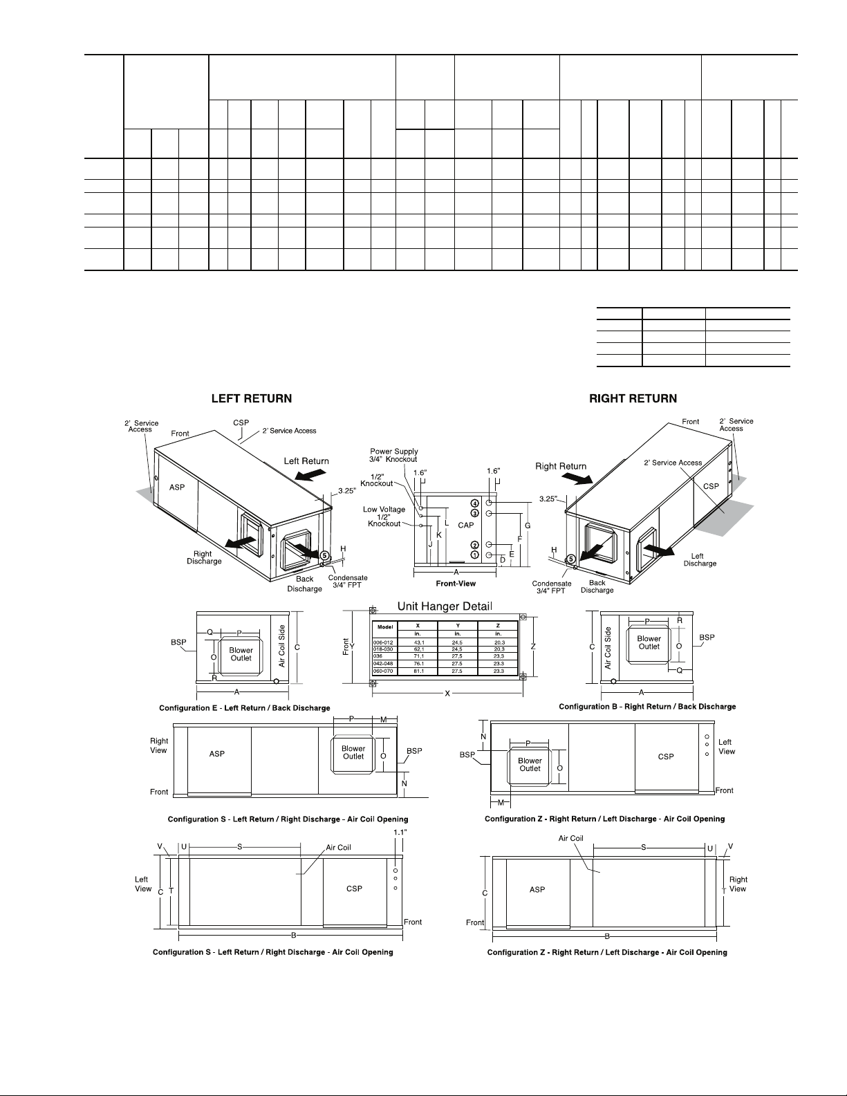
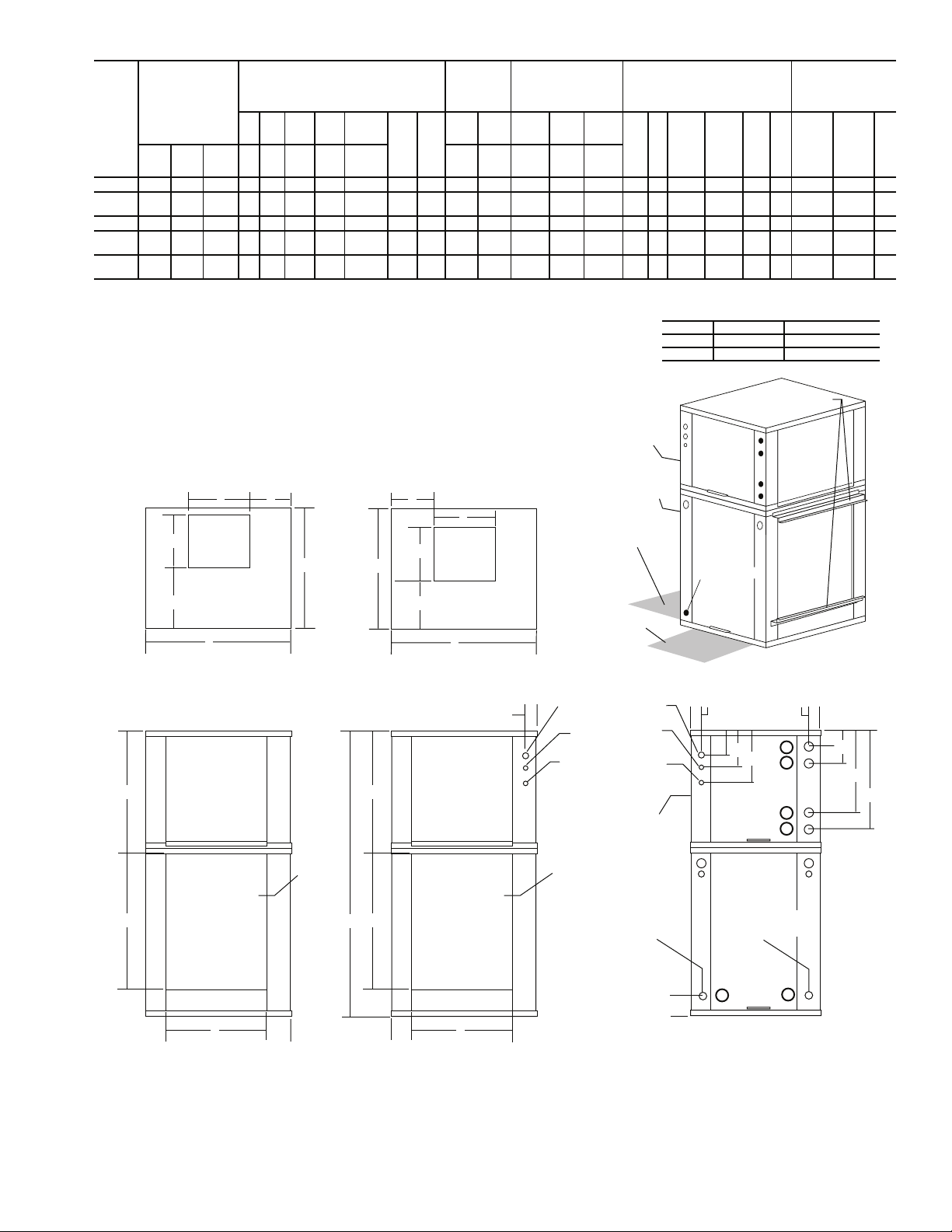
HORIZONTAL UNIT (50PSH) —
ed for indoor installation only. Be sure to allow adequate space
around the unit for servicing. Refer to Fig. 1 for an illustration of
a typical horizontal installation. See Fig. 2 for overall unit
dimensions.
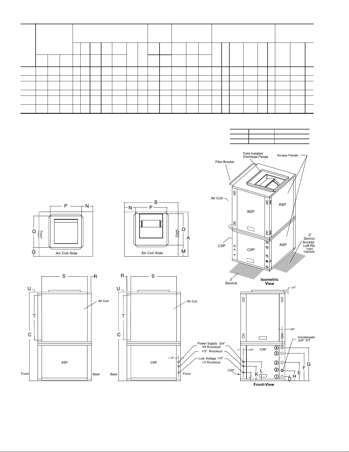
VERTICAL AND DOWNFLOW UNITS (50PSV, PSD) —
Vertical units are designed for indoor installations. While vertical units are typically installed in a floor-level closet or a small
mechanical room, the unit access guidelines for these units are
very similar to those described for horizontal units. See Fig. 3
and 4 for overall dimensions. Refer to Fig. 5 for an example of
a typical vertical installation. Refer to Fig. 6 for a sample
downflow installation.
Installation, operation and
Horizontal units are design-
GENERAL
This installation and start-up instructions literature is for
Aquazone™ single-stage water source heat pump systems.
CAUTION
To avoid equipment damage, do not use these units as a
source of heating or cooling during the construction process. The mechanical components and filters used in these
units quickly becomes clogged with construction dirt and
debris which may cause system damage.
2

Table 1 — Physical Data — 50PSH, PSV, PSD018-070 Units
50PS UNIT SIZE 006* 009* 012* 018 024 030 036 042 048 060 070
COMPRESSOR (1 Each) Rotary Scroll
FACTORY CHARGE R-410A (oz) 24 32 34 50 56 58 70 80 80 136 144
ECM FAN MOTOR AND BLOWER
Fan Motor (Hp) N/A N/A N/A
Blower Wheel Size (D x W) (in.) N/A N/A N/A 9 x 7 9 x 7 9 x 7 11 x 10 11 x 10 11 x 10 11 x 10 11 x 10
PSC FAN MOTOR AND BLOWER
(3 Speeds)
Fan Motor (Hp)
High Static Fan Motor (Hp) N/A N/A N/A
Blower Wheel Size (D x W) (in.) 6 x 5 6 x 5 6 x 5 9 x 7 9 x 7 9 x 7 10 x 10 10 x 10 10 x 10 11 x 10 11 x 10
Heat Exchanger Water Volume (gal.) 0.56 0.56 0.56 0.56 0.76 0.76 0.92 1.24 1.24 1.56 1.56
COAXIAL VOLUME (gal.) .17 .29 .45 .56 .76 .76 .92 1.24 1.24 1.56 1.56
WATER CONNECTION SIZE, FPT (in.)
HWG CONNECTION SIZE, FPT (in.) N/A N/A N/A
VERTICAL UPFLOW/DOWNFLOW
Air Coil Dimensions (H x W) (in.) 16 x 16 16 x 16 16 x 16 24 x 20 28 x 20 28 x 20 28 x 25 32 x 25 32 x 25 36 x 25 36 x 25
Throwaway Filter, Standard 1-in.,
Qty...Size 1...
Weight
Operating (lb) 126 146 150 252 266 268 327 414 416 441 443
Packag ed (lb) 136 156 160 262 276 278 337 424 426 451 453
HORIZONTAL
Air Coil Dimensions (H x W) (in.) 16 x 16 16 x 16 16 x 16 18 x 27 18 x 31 18 x 31 20 x 35 20 x 40 20 x 40 20 x 45 20 x 45
Throwaway Filter, Standard 1-in.,
Qty...Size 1...
Weight
Operating (lb) 136 156 160 257 266 268 327 414 416 441 443
Packag ed (lb) 146 166 170 267 276 278 337 424 426 451 453
Corner (lb)
Left Front 45.0 55.0 56.0 74.7 78.8 79.4 104.4 144.3 145.0 182.3 183.1
Left Rear 33.0 36.0 37.0 66.2 69.9 70.4 83.7 97.7 98.1 78.4 78.8
Right Front 30.0 33.0 34.0 63.6 67.2 67.7 74.9 92.1 92.6 72.5 72.8
Right Rear 28.0 32.0 33.0 47.5 50.2 50.5 64.0 79.9 80.3 107.8 108.3
ECM — Electronically Controlled Motor PSC — Permanent Split Capacitor
FPT — Female Pipe Thread TXV — Thermostatic Expansion Valve
HWG — Hot Water Generator
LEGEND *Unit sizes 006-012 not available on 50PSD unit.
1
/
25
1
/
2
16 x 20
16 x 20
1
/
20
1
/
2
1...
16 x 20
1...
16 x 20
1
/
8
1
/
2
1...
16 x 20
1...
16 x 20
1
/
2
1
/
6
1
/
5
3
/
4
1
/
2
1...
24 x 24
2...
18 x 18
1
/
2
1
/
5
1
/
3
3
/
4
1
/
2
1...
28 x 24
2...
18 x 18
NOTE: All units have spring compressor mountings, TXV expansion devices, and
in. and 3/4-in. electrical knockouts.
1
/
2
1
/
3
1
/
2
3
/
4
1
/
2
1...
28 x 24
2...
18 x 18
1
/
2
1
/
2
1
/
2
3
/
4
1
/
2
1...
28 x 30
1...
12 x 20;
1...
20 x 25
1
/
2
1
/
2
3
/
4
1111
1
/
2
2...
16 x 30
1...
18 x 20;
1...
20 x 24
111
3
/
4
3
/
4
1
/
2
2...
16 x 30
1...
18 x 20;
1...
20 x 24
11
1N/A
1
/
2
1...
16 x 30;
20 x 30
20 x 24
1...
2...
16 x 30;
20 x 30
20 x 24
1...
2...
1
/
2
1..
1
/2-
Step 2 — Check Unit — Upon receipt of shipment at
the jobsite, carefully check the shipment against the bill of
lading. Make sure all units have been received. Inspect the carton or crating of each unit, and inspect each unit for damage.
Ensure the shipping company makes proper notation of any
shortages or damage on all copies of the freight bill. Concealed
damage not discovered during unloading must be reported to
the shipping company within 15 days of receipt of shipment.
NOTE: It is the responsibility of the purchaser to file all
necessary claims with the shipping company.
1. Be sure that the location chosen for unit installation provides ambient temperatures maintained above freezing.
Well water applications are especially susceptible to
freezing.
2. Be sure the installation location is isolated from sleeping
areas, private offices and other acoustically sensitive
spaces.
NOTE: A sound control accessory package may be used
to help eliminate sound in sensitive spaces.
3. Check local codes to be sure a secondary drain pan is not
required under the unit.
4. Be sure unit is mounted at a height sufficient to provide
an adequate slope of the condensate lines. If an appropriate slope cannot be achieved, a field-supplied condensate
pump may be required.
5. Provide sufficient space for duct connection. Do not allow the weight of the ductwork to rest on the unit.
6. Provide adequate clearance for filter replacement and
drain pan cleaning. Do not allow piping, conduit, etc. to
block filter access.
7. Provide sufficient access to allow maintenance and
servicing of the fan and fan motor, compressor and coils.
Removal of the entire unit from the closet should not be
necessary.
8. Provide an unobstructed path to the unit within the closet
or mechanical room. Space should be sufficient to allow
removal of unit if necessary.
9. Provide ready access to water valves and fittings, and
screwdriver access to unit side panels, discharge collar,
and all electrical connections.
10. Where access to side panels is limited, pre-removal of the
control box side mounting screws may be necessary for
future servicing.
STORAGE — If the equipment is not needed immediately at
the jobsite, it should be left in its shipping carton and stored in a
clean, dry area of the building or in a warehouse. Units must be
stored in an upright position at all times. If carton stacking is
necessary, stack units a maximum of 3 high. Do not remove
any equipment from its shipping package until it is needed for
installation.
PROTECTION — Once the units are properly positioned on
the jobsite, cover them with either a shipping carton, vinyl film,
or an equivalent protective covering. Cap open ends of pipes
stored on the jobsite. This precaution is especially important in
areas where painting, plastering, or spraying of fireproof material, etc. is not yet complete. Foreign material that accumulates
within the units can prevent proper start-up and necessitate
costly clean-up operations.
3
Before installing any of the system components, be sure to
examine each pipe, fitting, and valve, and remove any dirt or
foreign material found in or on these components.
CAUTION
DO NOT store or install units in corrosive environments or
in locations subject to temperature or humidity extremes
(e.g., attics, garages, rooftops, etc.). Corrosive conditions
and high temperature or humidity can significantly reduce
performance, reliability, and service life. Always move
units in an upright position. Tilting units on their sides may
cause equipment damage.
INSPECT UNIT — To prepare the unit for installation, complete the procedures listed below:
1. Compare the electrical data on the unit nameplate with
ordering and shipping information to verify that the
correct unit has been shipped.
2. Do not remove the packaging until the unit is ready for
installation.
Filter Access
Field-supplied transition to
minimize pressure loss
Supply Air
Insulated supply duct with
at least one 90 degree elbow
to reduce air noise
(field-supplied)
Flexible
Connection
Field-Supplied
Electric Heat
(if applicable)
Aux Electric
Heat Disconnect
Power Wiring
Unit Power
Disconnect
(by others)
Unit Hanger
(factorysupplied)
3/8” threaded rods
(by others)
Return Air
(Ductwork
not shown)
Unit Power
3. Verify that the unit’s refrigerant tubing is free of kinks or
dents, and that it does not touch other unit components.
4. Inspect all electrical connections. Be sure connections are
clean and tight at their terminations.
5. Loosen compressor bolts until the compressor rides freely
on springs. Remove shipping restraints.
6. Remove the four
1
/4 in. shipping bolts from compressor
support plate (two bolts on each side) to maximize vibration and sound alternation.
CAUTION
Failure to remove shipping brackets from spring-mounted
compressors will cause excessive noise and could cause
component failure due to added vibration.
7. Remove any blower support cardboard from inlet of the
blower.
8. Locate and verify any accessory kit located in compressor
and/or blower section.
9. Remove any access panel screws that may be difficult to
remove once unit is installed.
Thermostat
Wiring
Stainless steel
braid hose
with integral
“J” swivel
(field-installed
accessory)
Ball Valve with optional
integral P/T plug (typical for supply
and return piping)
Balancing Valve (fieldinstalled accessory)
Low Pressure Drop Water
Control Valve (optional)
(field-installed accessory)
Building
Loop
Water Out
Water In
(field-installed accessory)
3/8” Threaded
Rod (by others)
Vibration Isolator
(white-compressor end
and red-blower end)
Washer
(by others)
Double Hex Nuts
(by others)
Integral hanger supportpre-attached in factory
UNIT HANGER ISOLATION DETAIL
Fig. 1 — Typical Installation — 50PSH Unit
A50-7728
4
WATER CONNECTIONS
F
HWG
In
G
HWG
Out
(in.)
H
Con-
densate
Loop
Wate r
FPT
1
/2N/A N/A N/A 3.8 6.3 8.8 5.3 4.1 9.0 9.0 5.3 4.1 17.1 15.3 2.1 1.0
3
/
4
4
4
OVER ALL
50PSH
UNIT
SIZE
006,009,
012
CABINET
(in.)
12 3 4 5
A
WidthBDepthCHeightDInEOut
22.4 43.1 17.3 3.7 9.7 N/A N/A 0.8
018 22.4 62.2 19.3 2.1 10.0 13.9 16.9 0.6
024,
22.4 62.2 19.3 2.1 10.0 13.9 16.9 0.63/
030
036 25.4 71.2 21.3 3.4 10.8 15.6 18.9 0.63/
042,
25.4 76.2 21.3 3.4 10.8 15.6 18.9 0.6 11/25.96 13.13 3.6 6.1 8.6 3.1 1.2 19.0 17.5 3.1 1.0 39.8 18.2 3.1 1.5
048
060,
25.4 81.2 21.3 3.4 10.8 15.6 18.9 0.6 11/25.96 13.13 3.6 6.1 8.6 3.1 1.2 19.0 17.5 3.1 1.0 44.8 18.2 3.1 1.5
070
NOTES:
1. Condensate is
2. Horizontal unit shipped with filter bracket only. This bracket should be
removed for return duct connection.
3. Discharge flange and hanger kit is factory installed.
4. Shaded areas are recommended service areas, not required.
3
/4-in. FPT copper.
a50-8231
WATER
CONNECTIONS (in.) UNITS WITH
HWR
12
HWG
FPT
Loop
Loop
In D
Out E
1
/22.1 10.0 3.6 6.1 8.6 3.6 2.0 12.5 15.5 3.6 2.0 28.1 16.2 2.3 1.5
1
/25.26 13.13 3.6 6.1 8.6 3.6 2.0 12.5 15.5 3.6 2.0 33.8 16.2 2.3 1.5
1
/25.96 13.13 3.6 6.1 8.6 3.1 1.2 19.0 17.5 3.1 1.0 34.8 18.2 3.1 1.5
ASP — Alternate Service Panel
BSP — Blower Service Panel
CAP — Control Access Panel
CSP — Compressor Service Panel
FPT — Female Pipe Thread
HWG — Hot Water Generator
HWR — Hot Water Reheat
LH — Left Hand
RH — Right Hand
ELECTRICAL
KNOCKOUTS
J
1
/
2
Cond
Low
Vol ta g e
LEGEND
(in.)
K
1
/
Cond
Ext
Pump
DISCHARGE CONNECTION (in.)
DUCT FLANGE INSTALLED
(±0.10 in.)
L
3
/
2
4
M
Cond
Power
Supply
(LH
rtrn)
NO
Supply
Height
P
Supply
Width
Q
(RH
rtrn)
RS
PSC BLOWER AIRFLOW
CONFIGURATION
CODE RETURN DISCHARGE
E Left Back
B Right Back
S Left Right
Z Right Left
RETURN
CONNECTION (in.)
USING RETURN
AIR OPENING
(±0.10 in.)
Depth
T
Return
Height
Return
UV
Fig. 2 — 50PSH Dimensional Data
5
WATER CONNECTIONS
F
HWG
In
G
HWG
Out
(in.)
H
Conden-
sate
Loop
Water
FPT
4
4
4
OVERALL
50PSV
UNIT
SIZE
006,009,
012
018 22.4 25.6 44.6 2.1 10.0 13.9 16.9 7.83/
024,
030
036 25.4 30.6 50.5 3.4 10.8 15.6 18.9 7.83/
042,
048
060,
070
NOTES:
1. Condensate is 3/4-in. FPT copper and is switchable from side to front.
2. Vertical unit shipped with filter bracket only, extending from unit 2.5-in.
This bracket should be removed for return duct connection.
3. Discharge flange field installed.
4. Shaded areas are recommended service areas, not required.
CABINET
(in.)
12 3 4 5
A
WidthBDepthCHeightDInEOut
22.4 21.6 34.5 3.7 9.7 N/A N/A 7.41/2N/A N/A N/A 3.8 6.3 8.8 6.7 6.3 9.0 9.0 6.7 2.3 17.1 15.3
22.4 25.6 48.5 2.1 10.0 13.9 16.9 7.83/
25.4 30.6 54.5 3.4 10.8 15.6 18.9 7.8 11/25.96 13.13 3.6 6.1 8.6 6.4 6.3 18.0 18.0 5.3 2.2 26.1 31.2
25.4 30.6 58.5 3.4 10.8 15.6 18.9 7.8 11/25.96 13.13 3.6 6.1 8.6 6.4 6.3 18.0 18.0 5.3 2.2 26.1 35.2
WATER
CONNECTIONS (in.) UNITS WITH
HWR
12
HWG
FPT
Loop
Loop
In D
Out E
1
/22.1 10.0 3.6 6.1 8.6 7.2 5.8 14.0 14.0 4.9 2.2 21.1 23.2
1
/25.26 13.13 3.6 6.1 8.6 7.2 5.8 14.0 14.0 4.9 2.2 21.1 27.2
1
/25.96 13.13 3.6 6.1 8.6 6.4 6.3 18.0 18.0 5.3 2.2 26.1 27.2
ASP — Alternate Service Panel
BSP — Blower Service Panel
CAP — Control Access Panel
CSP — Compressor Service Panel
FPT — Female Pipe Thread
HWG — Hot Water Generator
HWR — Hot Water Reheat
LH — Left Hand
RH — Right Hand
ELECTRICAL
KNOCKOUTS
J
1
/
2
Cond
Low
Vol t ag e
LEGEND
(in.)
K
1
/
Cond
Ext
Pump
2
L
3
/
4
Cond
Powe r
Supply
DISCHARGE CONNECTION (in.)
DUCT FLANGE INSTALLED
(±0.10 in.)
M
(LH
rtrn)
NO
Supply
Width
P
Supply
Depth
PSC BLOWER AIRFLOW
CONFIGURATION
CODE RETURN DISCHARGE
L Left Top
R Right Top
Q
(RH
rtrn)
RS
RETURN
CONNECTION (in.)
USING RETURN
AIR OPENING
(±0.10 in.)
Return
Depth
T
Return
Height
U
1.0
1.0
1.0
1.0
1.0
1.0
R - Configuration Right Return / Top Discharge
- Top View
Right Return
- Air Coil Opening
- Right Side View
a50-8183
L - Configuration Left Return / Top Discharge
- Top View
Left Return
- Air Coil Opening
- Left Side View
Fig. 3 — 50PSV Dimensional Data
6
WATER CONNECTIONS
F
HWG
In
G
HWG
Out
(in.)
H
Conden-
sate
Loop
Wate r
FPT
4
4
4
OVERALL
50PSD
UNIT
SIZE
018 22.4 25.6 48.4 2.1 10.0 13.9 16.9 3.63/
024,
030
036 25.4 30.6 54.5 3.4 10.8 15.6 18.9 3.63/
042,
048
060,
070
NOTES:
1. Condensate is
2. Vertical unit shipped with filter bracket only, extending from unit 2.5-in.
This bracket should be removed for return duct connection.
3. Downflow unit does not have discharge flange, and is rated for zero
clearance installation.
4. Shaded areas are recommended service areas, not required.
CABINET
(in.)
12 3 4 5
A
WidthBDepthCHeightDInEOut
22.4 25.6 52.5 2.1 10.0 13.9 16.9 3.63/
25.4 30.6 58.5 3.4 10.8 15.6 18.9 3.6 11/25.96 13.13 3.6 6.1 8.6 7.2 9.0 13.4 12.9 10.4 2.2 26.1 31.2 1.0
25.4 30.6 62.5 3.4 10.8 15.6 18.9 3.6 11/25.96 13.13 3.6 6.1 8.6 7.2 9.0 13.4 12.9 10.4 2.2 26.1 35.2 1.0
3
/4-in. FPT copper and is switchable from side to front.
WATER
CONNECTIONS (in.) UNITS WITH
HWR
12
HWG
FPT
Loop
Loop
In D
Out E
1
/22.1 10.0 3.6 6.1 8.6 6.7 8.4 10.1 9.1 10.8 2.2 21.1 23.2 1.0
1
/25.96 13.13 3.6 6.1 8.6 6.7 8.4 10.1 9.1 10.8 2.2 21.1 27.2 1.0
1
/25.96 13.13 3.6 6.1 8.6 7.2 9.0 13.4 12.9 10.4 2.2 26.1 27.2 1.0
ASP — Alternate Service Panel
BSP — Blower Service Panel
CAP — Control Access Panel
CSP — Compressor Service Panel
FPT — Female Pipe Thread
HWG — Hot Water Generator
HWR — Hot Water Reheat
LH — Left Hand
RH — Right Hand
KNOCKOUTS
J
1
/
2
Cond
Low
Vol ta ge
LEGEND
ELECTRICAL
(in.)
K
1
/
2
Cond
Ext
Pump
L
3
/
4
Cond
Power
Supply
DISCHARGE CONNECTION (in.)
DUCT FLANGE INSTALLED
(±0.10 in.)
M
(LH
rtrn)
NO
Supply
Width
CODE RETURN DISCHARGE
P
Supply
Depth
PSC BLOWER AIRFLOW
CONFIGURATION
L Left Bottom
R Right Bottom
Standard Filter Bracket
Q
(RH
rtrn)
RS
RETURN
CONNECTION (in.)
USING RETURN
AIR OPENING
(±0.10 in.)
Return
Depth
T
Return
Height
U
a50-7846ef
P
Blower
O
Opening
Front
Q
Air Coil Side
B
Right Return / Bottom Discharge
U
ASP
N
A
Air Coil
N
P
Blower
O
A
Opening
M
Air Coil Side
B
Left Return / Bottom Discharge
1.1
U
CSP
2' Optional Service
Access Right Rtn
(left opposite)
Front
2' Service
Power Supply 3/4”
HV Knockout
1/2” Knockout
Low Voltage 1/2”
LV Knockout
Air Coil
Access
CSP
CSP
ASP
CAP
BSP
Condensate 3/4”
FPT
Isometric View
1.6
L
K
J
CAP
BSP
ASP
1.6
G
4
3
F
E
D
2
1
T
Front
S
Right Return Right View -
Air Coil Opening
Front
Condensate
3/4” FPT
Right Return
H
Condensate
3/4” FPT
5
Left Return
Front-View
5
T
C
Back
R
Back
R
Left Return Left View -
Air Coil Opening
S
Fig. 4 — 50PSD Dimensional Data
7
Supply Air
Building
Flexible
Connection
Return
Air
Power
Thermostat
Wiring
Compressor
Access Panel
A50-7730
NOTE: Ball valve with integral pressure temperature plug recommended.
Loop
Water
Out
Water
In
Stainless steel
braid hose
with integral
“J” swivel
(field-installed
accessory)
integral P/T plug
(typical for supply and
return piping) (field-Installed
accessory)
Control Valve
(optional)
(field-installed
accessory)
Ball Valve with optional
Balancing Valve
(field-installed
accessory)
Low Pressure
Drop Water
Fig. 5 — Typical Vertical Installation — 50PSV Unit
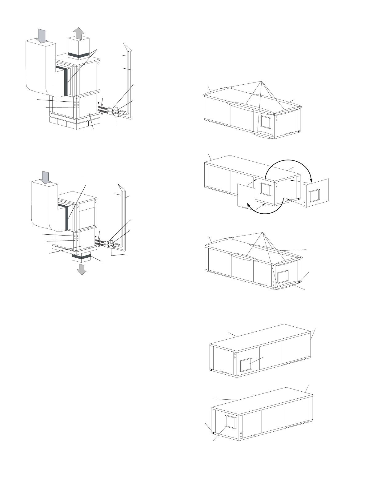
FIELD CONVERSION OF DISCHARGE AIR — The discharge air of the 50PSH horizontal units can be converted
between side and back discharge in the field. The conversion
process is the same for right and left return configurations. See
Fig. 7 and 8.
NOTE: It is not possible to convert return air between left or
right return models in the field due to refrigerant piping
changes.
Water
Connection End
Side Discharge
Water
Connection End
Remove Screws
Return Air
Rotate
Return Air
Flexible
Connection
Return
Air
Power
Thermostat
Wiring
Compressor
Access Panel
A50-7729
NOTE: Ball valve with integral pressure temperature plug recommended.
Supply Air
Building
Loop
Water
Out
Stainless
steel
braid hose
with
integral ”J”
swivel(fieldinstalled
accessory)
Flexible
Connection
Water
In
Balancing Valve
(field-installed
accessory)
Low Pressure
Drop Water
Control Valve
(optional)
(field-installed
accessory)
Ball Valve with
optional integral
P/T plug (typical for
supply and return
piping)(field-installed
accessory)
Fig. 6 — Typical Downflow Installation —
50PSD Unit
Step 3 — Locate Unit — The following guidelines
should be considered when choosing a location for a WSHP:
• Units are for indoor use only.
• Locate in areas where ambient temperatures are between
39 F and 102 F and relative humidity is no greater than
75%.
• Provide sufficient space for water, electrical and duct
connections.
• Locate unit in an area that allows easy access and removal
of filter and access panels.
• Allow enough space for service personnel to perform
maintenance.
• Return air must be able to freely enter the space if unit needs
to be installed in a confined area such as a closet.
NOTE: Correct placement of the horizontal unit can play an
important part in minimizing sound problems. Since
ductwork is normally applied to these units, the unit can be
placed so that the principal sound emission is outside the occupied space in sound-critical applications. A fire damper
may be required by the local code if a fire wall is penetrated.
Connection End
A50-6256
Return Air
Drain
Discharge Air
Move to Side
Water
Back Discharge
Replace Screws
Fig. 7 — Conversion Left Return,
Side Discharge to Back Discharge
Return Air
Supply
Duct
Side Discharge
Back Discharge
Connection End
Fig. 8 — Conversion Right Return,
Side Discharge to Back Discharge
Return Air
Drain
Discharge Air
Water
Connection End
Water
A50-6257
8
Preparation
— The unit should be on the ground in a well lit
area. Hung units should be taken down to ground level before
converting.
Side to Back Discharge Conversion
1. Remove screws to free the top and discharge panels. Set
screws aside for later use. See Fig. 7.
2. Remove the access panel and set aside.
3. Lift the discharge panel from side of unit and rotate it to
back using care not to damage blower wiring.
4. Check blower wire routing and connections for undue
tension or contact with sheet metal edges. Re-route if
necessary.
5. Check refrigerant tubing for contact with other components. Adjust if necessary.
6. Reinstall top panel using screws set aside in Step 1.
NOTE: Location for some screws at bottom of discharge
panel may have to be changed.
7. Manually spin fan wheel to check for obstructions.
Adjust for any obstruction found.
8. Replace access panel.
Back to Side Discharge Conversion
— Follow instructions
above for Side to Back Discharge Conversion, noting the
panels would be reversed.
Step 4 — Mount the Unit
HORIZONTAL UNIT (50PSH) — Horizontal units should
be mounted using the factory-installed hangers. Proper attachment of hanging rods to building structure is critical for safety.
See Fig. 1. Rod attachments must be able to support the weight
of the unit. See Table 1 for unit operating weights.
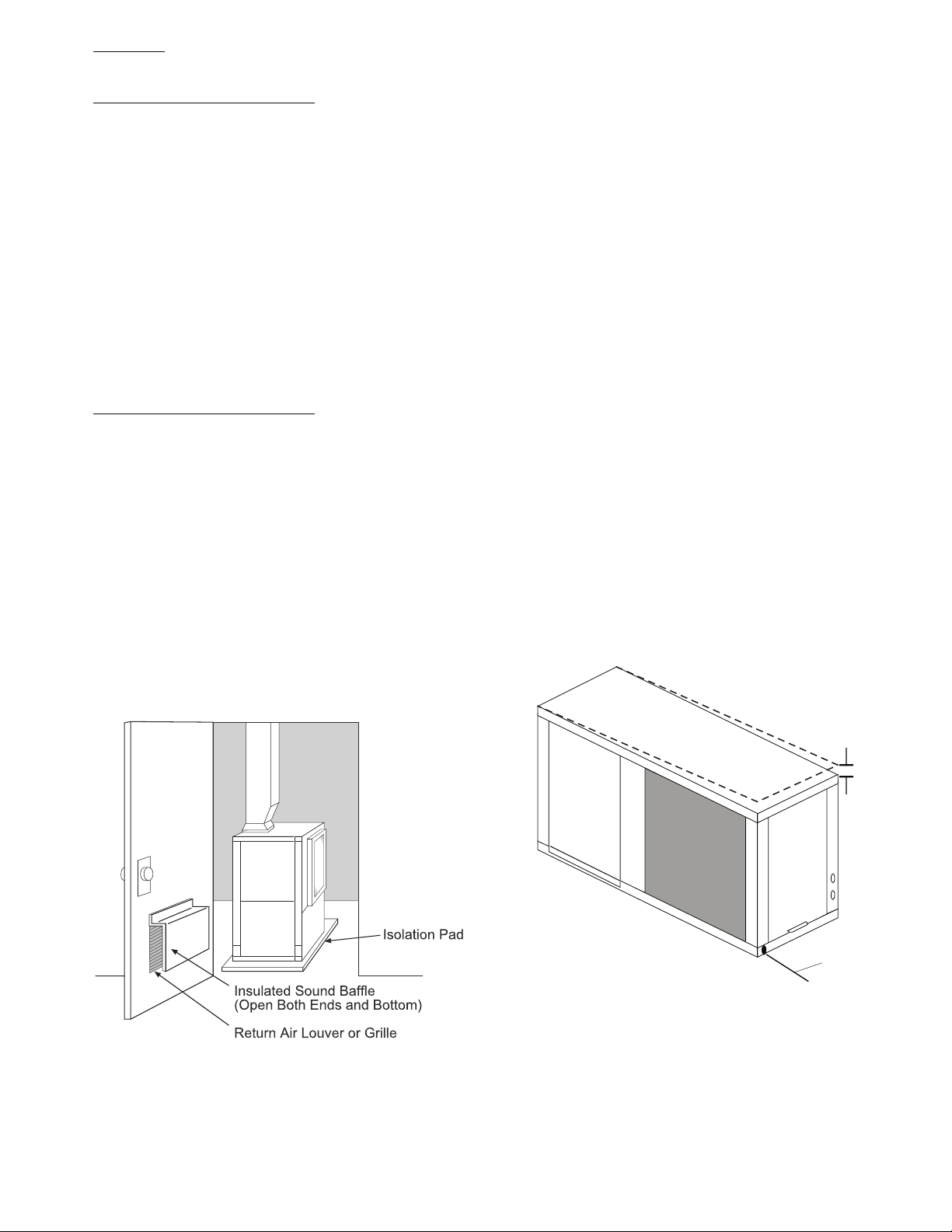
VERTICAL UNITS (50PSV, PSD) — Vertical and downflow
units are available in left or right return air configurations. See
Fig. 3 and 4. Mount the unit (except 50PSD) on a vibration
absorption pad slightly larger than the entire base to minimize
vibration transmission. It is not necessary to mount the unit on
the floor. See Fig. 9.
NOTE: Some codes require the use of a secondary drain pan
under vertical units. Check local codes for more information.
Step 5 — Check Duct System — Size the duct sys-
tem to handle the design airflow quietly.
NOTE: Depending on the unit, the fan wheel may have a ship-
ping support installed at the factory. This must be removed
before operating unit.
SOUND ATTENUATION — To eliminate the transfer of
vibration to the duct system, a flexible connector is recommended for both discharge and return air duct connections on
metal duct systems. The supply and return plenums should include internal duct liner of fiberglass or be made of duct board
construction to maximize sound attenuation of the blower.
Installing the WSHP unit to uninsulated ductwork in an unconditioned space is not recommended since it will sweat and
adversely affect the unit’s performance.
To reduce air noise, at least one 90-degree elbow could be
included in the supply and return air ducts, provided system
performance is not adversely impacted. The blower speed can
also be changed in the field to reduce air noise or excessive airflow, provided system performance is not adversely impacted.
EXISTING DUCT SYSTEM — If the unit is connected to
existing ductwork, consider the following:
• Verify that the existing ducts have the proper capacity to
handle the unit airflow. If the ductwork is too small, install
larger ductwork.
• Check existing ductwork for leaks and repair as necessary.
NOTE: Local codes may require ventilation air to enter the
space for proper indoor air quality. Hard-duct ventilation
may be required for the ventilating air supply. If hard
ducted ventilation is not required, be sure that a proper air
path is provided for ventilation air to unit to meet ventila-
tion requirement of the space.
Step 6 — Install Condensate Drain
HORIZONTAL UNIT (50PSH) — Slope the unit toward the
drain at
quired pitch, install a condensate at the unit to pump condensate to building drain.
1
/4 in. See Fig. 10. If it is not possible to meet the re-
A50-7731ef
Fig. 9 — 50PSV Units Mounted With
Vibration Absorption Pad
1/4Ó Pitch for
Drainage
Pitch Toward
Drain
A50-6260
Drain Connection
Fig. 10 — Horizontal Unit Pitch
Horizontal units are not internally trapped, therefore an external trap is necessary. Install each unit with its own individual
trap and means to flush or blow out the condensate drain line.
Do not install units with a common trap or vent. See Fig. 11 for
typical condensate connections.
NOTE: Never use a pipe size smaller than the connection.
9
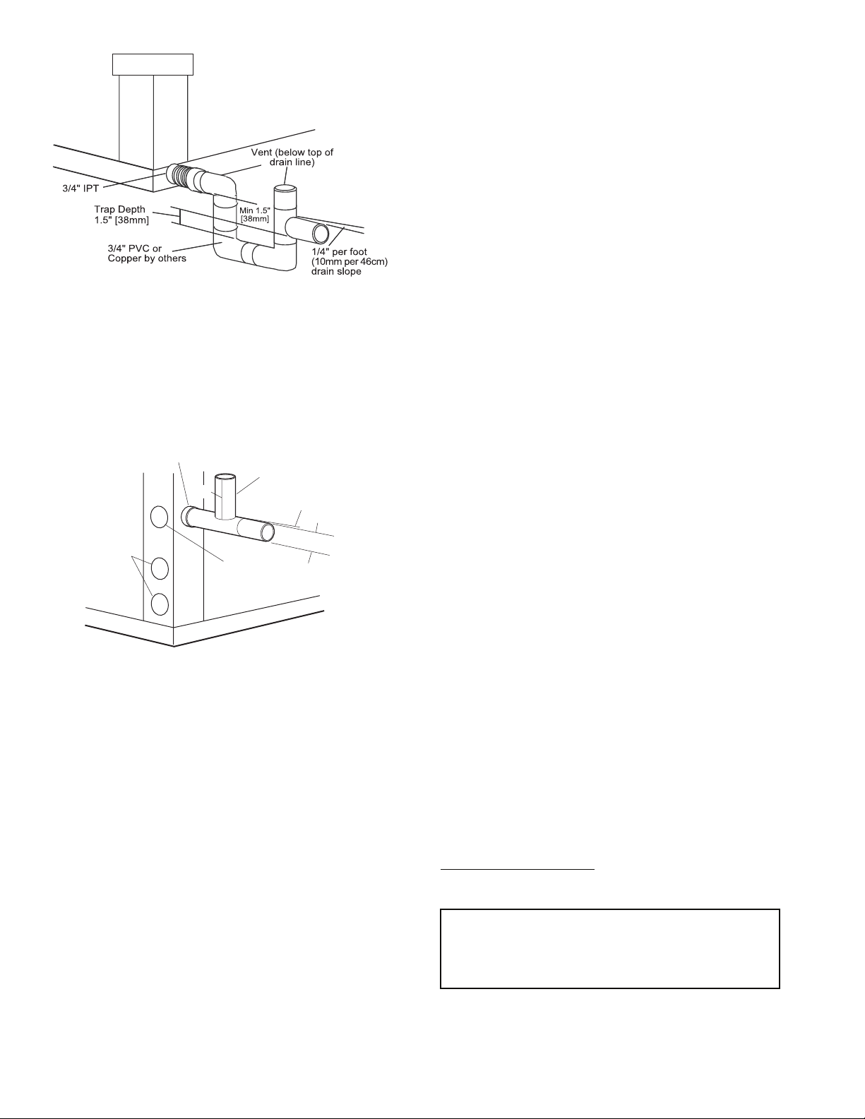
A50-7732
NOTE: Trap should be deep enough to offset maximum unit static
difference. A 4-in. trap is recommended.
Fig. 11 — Trap Condensate Drain Connection
VERTICAL UNITS (50PSV, PSD) — Each unit uses a condensate hose inside all cabinets as a trapping loop, therefore an
external trap is not necessary. See Fig. 12.
Each unit must be installed with its own individual vent and
means to flush or blow out the condensate drain line. Do not install units with a common trap or vent.
3/4” Copper FPT/PVC
1/2”
Water
Connections
A50-6262
NOTE: Unit does not need to be sloped toward drain.
3/4” PVC
Vent
Alternate
Condensate
Location
1/4” per foot
slope to drain
1/2”
Fig. 12 — Vertical Condensate Connection
VENTING — Install a vent in the condensate line of any
application that may allow dirt or air to collect in the line. Consider the following:
• Always install a vent where an application requires a long
horizontal run.
• Always install a vent where large units are working against
higher external static pressure and to allow proper drainage
for multiple units connected to the same condensate main.
• Be sure to support the line where anticipated sagging from
the condensate or when “double trapping” may occur.
• If condensate pump is present on unit, be sure drain connec-
tions have a check valve to prevent back flow of condensate
into other units.
Step 7 — Pipe Connections — Depending on the
application, there are 3 types of WSHP piping systems to
choose from: water loop, ground-water and ground loop. Refer
to Piping Section of Carrier System Design Manual for additional information.
All WSHP units use low temperature soldered female pipe
thread fittings for water connections to prevent annealing and
out-of-round leak problems which are typically associated with
high temperature brazed connections. Refer to Table 1 for
connection sizes. When making piping connections, consider
the following:
• Use a backup wrench when making screw connections to
unit to prevent internal damage to piping.
• Insulation may be required on piping to avoid condensation
in the case where fluid in loop piping operates at temperatures below dew point of adjacent air.
• Piping systems that contain steel pipes or fittings may be
subject to galvanic corrosion. Dielectric fittings may be
used to isolate the steel parts of the system to avoid galvanic
corrosion.
WATER LOOP APPLICATIONS — Water loop applications
usually include a number of units plumbed to a common piping system. Maintenance to any of these units can introduce air
into the piping system. Therefore, air elimination equipment
comprises a major portion of the mechanical room plumbing.
The flow rate is usually set between 2.25 and 3.5 gpm per
ton of cooling capacity. For proper maintenance and servicing,
pressure-temperature (P/T) ports are necessary for temperature
and flow verification.
Cooling tower/boiler systems typically utilize a common
loop maintained at 60 to 95 F. The use of a closed circuit evaporative cooling tower with a secondary heat exchange between
the tower and the water loop is recommended. If an open type
cooling tower is used continuously, chemical treatment and filtering will be necessary.
In addition to complying with any applicable codes, consid-
er the following for system piping:
• Piping systems using water temperatures below 50 F
require
1
/2-in. closed cell insulation on all piping surfaces to
eliminate condensation.
• Avoid all plastic to metal threaded fittings due to the potential to leak. Use a flange fitted substitute.
• Teflon tape thread sealant is recommended to minimize
internal fouling of the heat exchanger.
• Use backup wrench. Do not overtighten connections.
• Route piping to avoid service access areas to unit.
• Flush the piping system prior to operation to remove dirt
and foreign materials from the system.
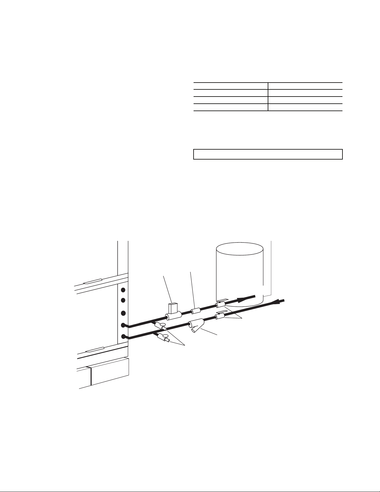
GROUND-WATER APPLICATIONS — Typical groundwater piping is shown in Fig. 13. In addition to complying
with any applicable codes, consider the following for system piping:
• Install shut-off valves for servicing.
• Install pressure-temperature plugs to measure flow and
temperature.
• Connect boiler drains and other valves using a “T” connector to allow acid flushing for the heat exchanger.
• Do not overtighten connections.
• Route piping to avoid service access areas to unit.
• Use PVC SCH80 or copper piping material.
NOTE: PVC SCH40 should not be used due to system high
pressure and temperature extremes.
Water Supply and Quantity
— Check water supply. Water
supply should be plentiful and of good quality. See Table 2 for
water quality guidelines.
IMPORTANT: Failure to comply with the above required
water quality and quantity limitations and the closedsystem application design requirements may cause damage
to the tube-in-tube heat exchanger. This damage is not the
responsibility of the manufacturer.
10
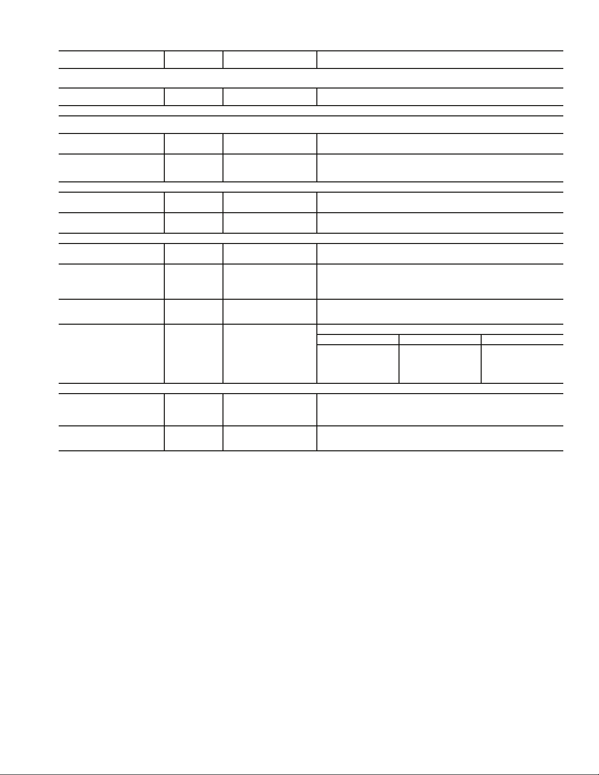
Table 2 — Water Quality Guidelines
CONDITION
Scaling Potential — Primary Measurement
Above the given limits, scaling is likely to occur. Scaling indexes should be calculated using the limits below.
pH/Calcium
Hardness Method
Index Limits for Probable Scaling Situations (Operation outside these limits is not recommended.)
Scaling indexes should be calculated at 150 F for direct use and HWG applications, and at 90 F for indirect HX use. A monitoring plan should be
implemented.
Ryznar Stability Index
Langelier Saturation Index
Iron Fouling
Iron Fe2+ (Ferrous)
(Bacterial Iron Potential)
Iron Fouling
Corrosion Prevention††
pH
Hydrogen Sulfide (H2S)
Ammonia Ion as Hydroxide,
Chloride, Nitrate and Sulfate
Compounds
Maximum Chloride Levels Maximum allowable at maximum water temperature.
Erosion and Clogging
Particulate Size and Erosion
Brackish
LEGEND
HWG — Hot Water Generator
HX — Heat Exchanger
N/A — Design Limits Not Applicable Considering Recirculating
NR — Application Not Recommended
SS — Stainless Steel
*Heat exchanger materials considered are copper, cupronickel, 304 SS
(stainless steel), 316 SS, titanium.
†Closed recirculating system is identified by a closed pressurized piping
system.
**Recirculating open wells should obser ve the open recirculating design
considerations.
Potable Water
HX
MATERIAL*
All N/A pH < 7.5 and Ca Hardness, <100 ppm
All N/A
All N/A
All N/A
All N/A
All
All N/A
All N/A
Copper N/A
Cupronickel N/A <150 ppm NR NR
304 SS N/A <400 ppm <250 ppm <150 ppm
316 SS N/A <1000 ppm <550 ppm <375 ppm
Titanium N/A >1000 ppm >550 ppm >375 ppm
All
All N/A
CLOSED
RECIRCULATING†
Monitor/treat as needed.
<10 ppm of particles and a
maximum velocity of 6 fps.
6 - 8.5
Filtered for maximum
800 micron size.
OPEN LOOP AND RECIRCULATING WELL**
6.0 - 7.5
If >7.5 minimize steel pipe use.
–0.5 to +0.5
Based upon 150 F HWG and direct well, 85 F indirect well HX.
If Fe2+ (ferrous) >0.2 ppm with pH 6 - 8, O2<5 ppm check for iron bacteria.
Minimize steel pipe below 7 and no open tanks with pH <8.
At H2S>0.2 ppm, avoid use of copper and cupronickel piping of HXs.
Copper alloy (bronze or brass) cast components are okay to <0.5 ppm.
50 F (10 C) 75 F (24 C) 100 F (38 C)
<20 ppm NR NR
<10 ppm (<1 ppm “sandfree” for reinjection) of par ticles and a maximum
velocity of 6 fps. Filtered for maximum 800 micron size. Any particulate that
is not removed can potentially clog components.
Use cupronickel heat exchanger when concentrations of calcium or sodium
chloride are greater than 125 ppm are present. (Seawater is approximately
25,000 ppm.)
††If the concentration of these corrosives exceeds the maximum allow-
able level, then the potential for serious corrosion problems exists.
Sulfides in the water quickly oxidize when exposed to air, requiring that
no agitation occur as the sample is taken. Unless tested immediately
at the site, the sample will require stabilization with a few drops of one
Molar zinc acetate solution, allowing accurate sulfide determination up
to 24 hours after sampling. A low pH and high alkalinity cause system
problems, even when both values are within ranges shown. The term
pH refers to the acidity, basicity, or neutrality of the water supply.
Below 7.0, the water is considered to be acidic. Above 7.0, water is
considered to be basic. Neutral water contains a pH of 7.0.
To convert ppm to grains per gallon, divide by 17. Hardness in mg/l is
equivalent to ppm.
If <–0.5 minimize steel pipe use.
<0.2 ppm (Ferrous)
<0.5 ppm of Oxygen
Above this level deposition will occur.
6 - 8.5
<0.5 ppm
Rotten egg smell appears at 0.5 ppm level.
<0.5 ppm
11
In all applications, the quality of the water circulated
through the heat exchanger must fall within the ranges listed in
the Water Quality Guidelines table. Consult a local water firm,
independent testing facility, or local water authority for specific
recommendations to maintain water quality within the published limits.
GROUND-LOOP APPLICATIONS — Temperatures between 25 and 110 F and a cooling capacity of 2.25 to 3 gpm of
flow per ton is recommended. In addition to complying with
any applicable codes, consider the following for system piping:
• Limit piping materials to only polyethylene fusion in the
buried sections of the loop.
• Do not use galvanized or steel fittings at any time due to
corrosion.
• Avoid all plastic to metal threaded fittings due to the poten-
tial to leak. Use a flange fitted substitute.
• Do not overtighten connections.
• Route piping to avoid service access areas to unit.
• Use pressure-temperature (P/T) plugs to measure flow of
pressure drop.
INSTALLATION OF SUPPLY AND RETURN HOSE
KIT — Follow these piping guidelines.
1. Install a drain valve at the base of each supply and return
riser to facilitate system flushing.
2. Install shutoff/balancing valves and unions at each unit to
permit unit removal for servicing.
3. Place strainers at the inlet of each system circulating
pump.
4. Select the proper hose length to allow slack between connection points. Hoses may vary in length by +2% to –4%
under pressure.
5. Refer to Table 3. Do not exceed the minimum bend radius
for the hose selected. Exceeding the minimum bend radius may cause the hose to collapse, which reduces water
flow rate. Install an angle adapter to avoid sharp bends
in the hose when the radius falls below the required
minimum.
NOTE: Piping must comply with all applicable codes.
Table 3 — Metal Hose Minimum Bend Radii
HOSE DIAMETER (in.) MINIMUM BEND RADII (in.)
1
/
2
3
/
4
15
21/
2
4
1
/
2
Insulation is not required on loop water piping except where
the piping runs through unheated areas or outside the building
or when the loop water temperature is below the minimum expected dew point of the pipe ambient. Insulation is required if
loop water temperature drops below the dew point.
IMPORTANT: Do not bend or kink supply lines or hoses.
Pipe joint compound is not necessary when Teflon threaded
tape is pre-applied to hose assemblies or when flared-end
connections are used. If pipe joint compound is preferred, use
compound only in small amounts on the male pipe threads of
the fitting adapters. Prevent sealant from reaching the flared
surfaces of the joint.
NOTE: When anti-freeze is used in the loop, assure that it is
compatible with Teflon tape or pipe joint compound employed.
Maximum allowable torque for brass fittings is 30 ft-lb. If a
torque wrench is not available, tighten finger-tight plus one
quarter turn. Tighten steel fittings as necessary.
Water
Control
Valve
(field-installed
accessory)
Flow
Regulator
(field-installed
accessory)
Boiler
Drains
(field-installed)
Pressure
Ta nk
Water Out
Shut-Off
Valve (field-installed accessory)
Strainer (field-installed accessory)
(16 to 20 mesh recommended for
filter sediment)
Fig. 13 — Typical Ground-Water Piping Installation
A50-7733
Water In
From Pump
12
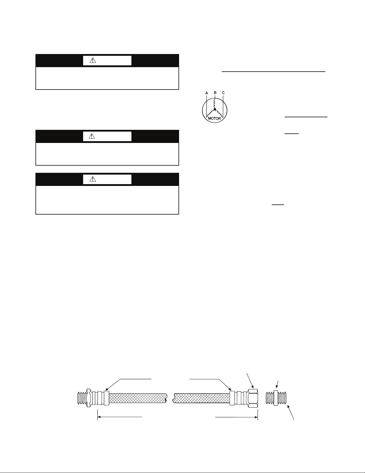
Optional pressure-rated hose assemblies designed specifically for use with Carrier units are available. Similar hoses can
be obtained from alternate suppliers. Supply and return hoses
are fitted with swivel-joint fittings at one end to prevent kinking during installation.
CAUTION
Backup wrench is required when tightening water connections to prevent water line damage. Failure to use a backup
wrench could result in equipment damage.
Refer to Fig. 14 for an illustration of a supply/return hose
kit. Male adapters secure hose assemblies to the unit and risers.
Install hose assemblies properly and check them regularly to
avoid system failure and reduced service life.
Step 8 — Wire Field Power Supply
WARNING
To avoid possible injury or death due to electrical shock,
open the power supply disconnect switch and secure it in
an open position during installation.
CAUTION
Use only copper conductors for field-installed electrical
wiring. Unit terminals are not designed to accept other
types of conductors. Failure to use copper conductors could
result in equipment damage.
All field-installed wiring, including the electrical ground,
MUST comply with the National Electrical Code (NEC) as
well as applicable local codes. In addition, all field wiring must
conform to the Class II temperature limitations described in the
NEC.
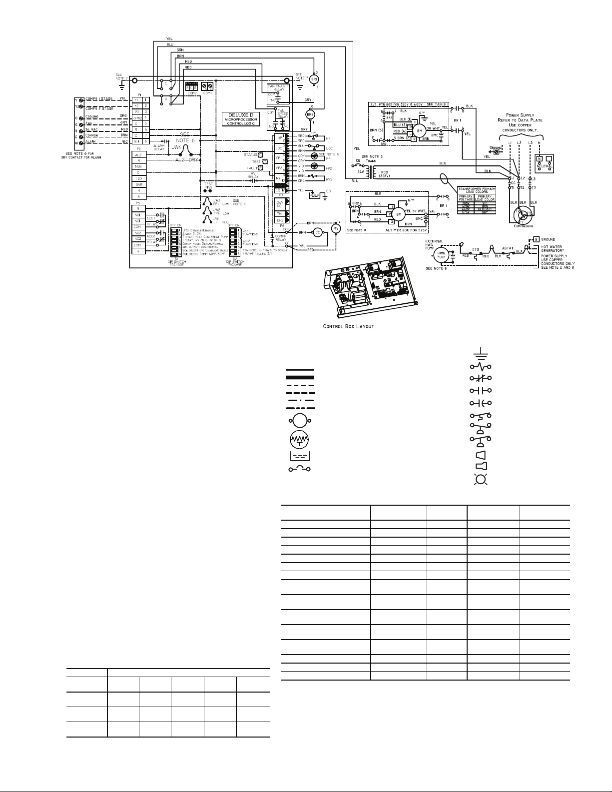
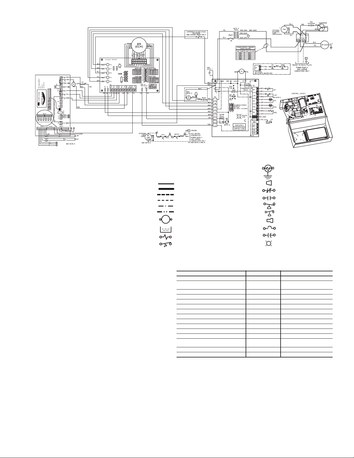
Refer to unit wiring diagrams Fig. 15-25 for a schematic of
the field connections, which must be made by the installing (or
electrical) contractor. Refer to Tables 4-6 for fuse sizes.
Consult the unit wiring diagram located on the inside of the
compressor access panel to ensure proper electrical hookup.
The installing (or electrical) contractor must make the field
connections when using field-supplied disconnect.
Operating voltage must be the same voltage and phase as
shown in electrical data shown in Tables 4-6.
Make all final electrical connections with a length of flexible conduit to minimize vibration and sound transmission to
the building.
POWER CONNECTION — Make line voltage connection
by connecting the incoming line voltage wires to the line
side of the compressor contactor terminal as shown in
Fig. 26. See Tables 4-6 for amperage ratings to provide correct wire and maximum overcurrent protection sizing.
SUPPLY VOLTAGE — Operating voltage to unit must be
within voltage range indicated on unit nameplate.
On 3-phase units, voltages under load between phases must
be balanced within 2%. Use the following formula to determine the percentage voltage imbalance:
% Voltage Imbalance
= 100 x
Example: Supply voltage is 460-3-60.
Determine maximum deviation from average voltage:
(AB) 457 – 452 = 5 v
(BC) 464 – 457 = 7 v
(AC) 457 – 455 = 2 v
Maximum deviation is 7 v.
Determine percent voltage imbalance.
% Voltage Imbalance = 100 x
below the maximum allowable 2%.
imbalance constitutes abuse and may cause damage to electrical components.
NOTE: If more than 2% voltage imbalance is present, contact
your local electric utility.
208-VOLT OPERATION — All 208-230 volt units are factory
wired for 208 volts. The transformers may be switched to
230-volt operation by switching the red (208 volt) wire with
the orange (230 volt) wire at the L1 terminal.
460-VOLT OPERATION — Units using 460-v and an
ECM (electronically commutated motor) fan motor, modulating HWR, and/or internal secondary pump will require a
neutral wire from the supply side in order to feed accessory
with 265-v.
max voltage deviation from average voltage
average voltage
AB = 452 volts
BC = 464 volts
AC = 455 volts
Average Voltage =
= 1.53%
This amount of phase imbalance is satisfactory as it is
Operation on improper line voltage or excessive phase
452 + 464 + 455
1371
=
3
= 457
7
457
3
A50-7734
Swivel
Brass
Rib Crimped
Fitting
Length
(2 ft Length Standard)
Fig. 14 — Supply/Return Hose Kit
13
Brass
Fitting
MPT
LEGEND
AL — Alarm Relay Contacts
ASTAT — Aquastat
BR — Blower Relay
CB — Circuit Breaker
CC — Compressor Contactor
CO — Condensate Overflow Sensor
COMPR — Compressor
DTS — Discharge Temp Switch
FP1 — Water Coil Freeze Protection Sensor
FP2 — Air Coil Freeze Protection Sensor
HP — High-Pressure Switch
HWG — Hot Water Generator
JW — Jumper Wire
LOC — Loss of Charge Pressure Switch
MV — Motorized Valve
NEC — National Electrical Code
PSC — Permanent Split Capacitor
P1 — Field Wiring Terminal Block
RVS — Reversing Valve Solenoid
*Optional.
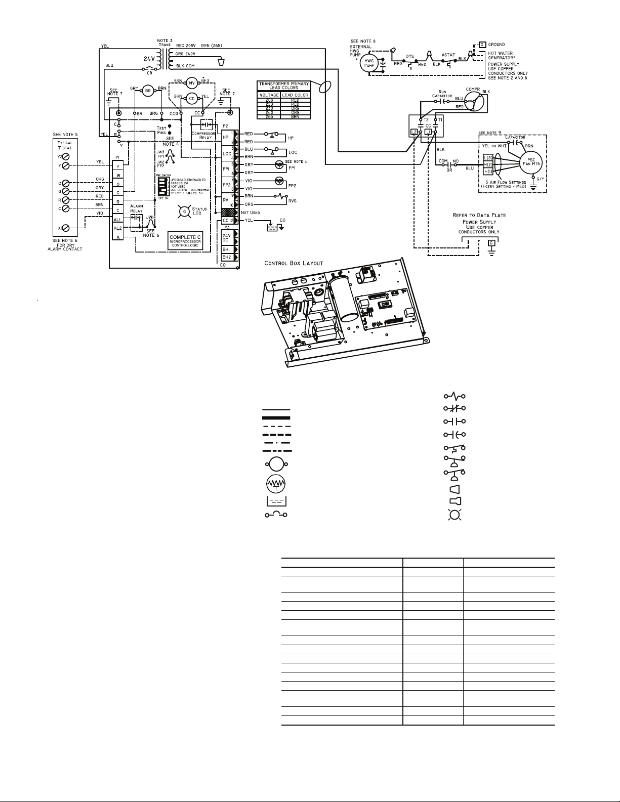
NOTES:
1. Compressor and blower motor thermally protected internally.
2. All wiring to the unit must comply with NEC and local codes.
3. 208/230 v transformer will be connected for 208 v operation. For
230 v operation, disconnect RED lead at L1 and attach ORANGE
lead to L1. Insulate open end of RED lead. Transformer is energy
limiting or may have circuit breaker.
4. FP1 thermistor provides freeze protection for water. When using
antifreeze solutions, cut JW3 jumper.
5. Check installation wiring information for specific thermostat hookup.
Refer to thermostat installation instructions for wiring to the unit.
Thermostat wiring must be “Class 1” and voltage rating equal to or
greater than unit supply voltage.
6. 24-v alarm signal shown. For dry alarm contact, cut JW1 jumper
and dry contact will be available between AL1 and AL2.
7. Transformer secondary ground via Complete C board standoffs and
screws to control box. (Ground available from top two standoffs as
shown.)
8. Aquastat is supplied with unit and must be wired in series with the
hot leg to the pump. Aquastat is rated for voltage up to 277 v.
9. Fan motors factory wired for medium speed. For high and low speed
remove BLU wire from fan motor speed tap ‘M’ and connect to ‘H’
for high or ‘L’ for low.
TRANS — Transformer
UPS — Unit Performance Sentinel
Solenoid Coil
Factory Low Voltage Wiring
Factory Line Voltage Wiring
Field Low Voltage Wiring
Field Line Voltage Wiring
Printed Circuit Trace
Optional Wiring
Relay/Contactor Coil
Thermistor
Condensate Pan
Circuit Breaker
COMPLETE C CONTROLLER FAULT CODES
DESCRIPTION OF OPERATION LED ALARM RELAY
Normal Mode ON Open
Normal Mode with UPS Warning ON
Complete C is Non-Functional OFF Open
Fault Retry Slow Flash Open
Lockout Fast Flash Closed
Over/Under Voltage Shutdown Slow Flash
Test Mode-No Fault in Memory Flashing Code 1 Cycling Code 1
Test Mode-HP Fault in Memory Flashing Code 2 Cycling Code 2
Test Mode-LP Fault in Memory Flashing Code 3 Cycling Code 3
Test Mode-FP1 Fault in Memory Flashing Code 4 Cycling Code 4
Test Mode-FP2 Fault in Memory Flashing Code 5 Cycling Code 5
Test Mode-CO Fault in Memory Flashing Code 6 Cycling Code 6
Test Mode-Over/Under Shutdown
in Memory
Test Mode-UPS in Memory Flashing Code 8 Cycling Code 8
Swapped FP1/FP2 Lockout Flashing Code 9 Cycling Code 9
Flashing Code 7 Cycling Code 7
Relay Contacts - N.C.
Relay Contacts - N.O.
Capacitor
Temperature Switch
Low Pressure Switch
High Pressure Switch
Wire Nut
Splice Cap
G
LED
Cycle (Closed 5 Sec.
Open 25 Sec.)
(Closed After 15 Min.)
Open
Fig. 15 — Units with Complete C Controller, Single-Phase
14
AL — Alarm Relay Contacts
ASTAT — Aquastat
BM — Blower Motor
BMC — Blower Motor Capacitor
BR — Blower Relay
CB — Circuit Breaker
CC — Compressor Contactor
CO — Condensate Overflow Sensor
COMPR — Compressor
DTS — Discharge Temp Switch
FP1 — Water Coil Freeze Protection Sensor
FP2 — Air Coil Freeze Protection Sensor
HP — High-Pressure Switch
HWG — Hot Water Generator
JW — Jumper Wire
LOC — Loss of Charge Pressure Switch
MV — Motorized Valve
NEC — National Electric Code
*Optional.
NOTES:
1. Compressor and blower motor thermally protected inter nally.
2. All wiring to the unit must comply with NEC and local codes.
3. Transformer is wired to 460 v (BLK/RED) lead for 460/60/3 units,
575 v (GRY) lead for 575/60/3. Transformer is energy limiting or may
have circuit breaker.
4. FP1 ther mistor provides freeze protection for water. When using antifreeze solutions, cut JW3 jumper.
5. Check installation wiring information for specific thermostat hookup.
Refer to thermostat installation instructions for wiring to the unit.
Thermostat wiring must be “Class 1” and voltage rating equal to or
greater than unit supply voltage.
6. 24-v alar m signal shown. For dry alarm contact, cut JW4 jumper and
dry contact will be available between AL1 and AL2.
7. Transformer secondary ground via Deluxe D board standoffs and
screws to control box. (Ground available from top two standoffs as
shown.)
8. Aquastat is supplied with unit and must be wired in series with the
hot leg to the pump. Aquastat is rated for voltage up to 277 v.
9. Blower motor is factory wired for high and low speeds. No other combination is available.
10. The 460-v units using an ECM (electronically commutated motor) fan
motor, modulating HWR, and/or an internal secondary pump will
require a neutral wire from the supply side in order to feed the accessory with 265-v.
TABLE 1 WIRE NUMBER
Blower
Speeds
Factory
HI + MED
HI + LOW
MED + LOW
12345
BM(H) to
BM(H) to
BM(H) to
BR2(6)
BR2(6)
BR2(3)
BM(R) to
BR2(3)
BM(R) to
BR2(3)
BM(R) to
BR2(3)
BM(M) to
BR2(7)
Not Used
BM(M) to
BR2(6)
Not Used
BM(L) to
BR2(7)
BM(L) to
BR2(7)
BR2(6) to
BR2(4)
BR2(6) to
BR2(4)
BR2(2) to
BR2(4)
LEGEND
P1 — Field Wiring Terminal Block
RVS — Reversing Valve Solenoid
TRANS — Transformer
Normal Mode ON OFF Note 2 Open
Deluxe D is Non-Functional OFF OFF OFF Open
Test Mode — ON Note 2 Cycle (Note 3)
Night Setback Flashing Code 2 — Note 2 —
Emergency Shut Down Flashing Code 3 — Note 2 —
Invalid Thermostat Inputs Flashing Code 4 — Note 2 —
No Fault in Memory ON OFF Flashing Code 1 Open
HP Fault/(Lockout) Note 1
LP Fault/(Lockout) Note 1
FP1 Fault/(Lockout) Note 1
FP2 Fault/(Lockout) Note 1
CC Fault/(Lockout) Note 1
Over-Under Voltage Slow Flash OFF Flashing Code 7 Open (Note 4)
Normal Mode with UPS ON OFF Flashing Code 8 Cycle (Note 5)
Swapped FP1/FP2 Lockout Fast Flash OFF Flashing Code 9 Closed
NOTES:
1. Status LED (GREEN) Slow Flash - Controller In - Fault Retry Mode. Fast Flash - Controller in Lockout Mode. Slow Flash = 1 Flash per every 2 seconds. Fast Flash = 2 Flashes per every 1 second.
2. Fault LED (RED) flashes a code representing last fault in memory. If no fault in memory code 1 is
flashed.
3. Cycles appropriate code, by cycling alarm relay in the same sequence as fault LED.
4. Alarm relay closes after 15 minutes.
5. Alarm relay cycles. Closed for 5 seconds and open for 25 seconds.
Factory Low Voltage Wiring
Factory Line Voltage Wiring
Field Low Voltage Wiring
Field Line Voltage Wiring
Printed Circuit Trace
Optional Wiring
Relay/Contactor Coil
Thermistor
Condensate Pan
Circuit Breaker
OPERATION
DELUXE D CONTROLLER FAULT CODES
STATUS LED
(GREEN)
Slow Flash/
(Fast Flash)
Slow Flash/
(Fast Flash)
Slow Flash/
(Fast Flash)
Slow Flash/
(Fast Flash)
Slow Flash/
(Fast Flash)
TEST LED
(YELLOW)
OFF Flashing Code 2 Open/(Closed)
OFF Flashing Code 3 Open/(Closed)
OFF Flashing Code 4 Open/(Closed)
OFF Flashing Code 5 Open/(Closed)
OFF Flashing Code 6 Open/(Closed)
Ground
Solenoid Coil
Relay Contacts - N.C.
Relay Contacts - N.O.
Capacitor
Temperature Switch
Low Pressure Switch
High Pressure Switch
Wire Nut
Splice Cap
G
LED
FAULT LED
(RED)
ALARM
RELAY
Fig. 16 — Units with Deluxe D Controller, Three-Phase (460/575 V)
15
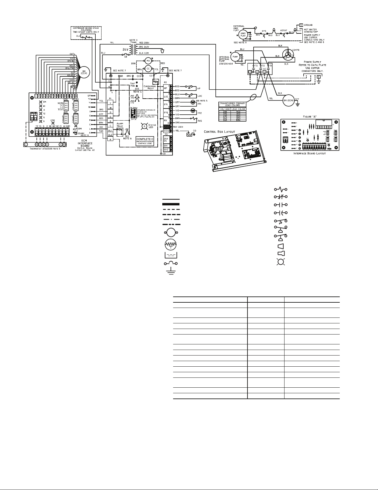
AL — Alarm Relay Contacts
ASTAT — Aquastat
BM — Blower Motor
BR — Blower Relay
CB — Circuit Breaker
CC — Compressor Contactor
CO — Condensate Overflow Sensor
COMPR — Compressor
DTS — Discharge Temp Switch
ECM — Electronically Commutated Motor
FP1 — Water Coil Freeze Protection Sensor
FP2 — Air Coil Freeze Protection Sensor
HP — High-Pressure Switch
HWG — Hot Water Generator
JW — Jumper Wire
LOC — Loss of Charge Pressure Switch
LWT — Leaving Water Temperature
MV — Motorized Valve
NEC — National Electric Code
P1 — Field Wiring Terminal Block
*Optional.
LEGEND
RVS — Reversing Valve Solenoid
TRANS — Transformer
UPS — Unit Performance Sentinel
Factory Low Voltage Wiring
Factory Line Voltage Wiring
Field Low Voltage Wiring
Field Line Voltage Wiring
Printed Circuit Trace
Optional Wiring
Relay/Contactor Coil
Thermistor
Condensate Pan
Circuit Breaker
Ground
Solenoid Coil
Relay Contacts - N.C.
Relay Contacts - N.O.
Capacitor
Temperature Switch
Low Pressure Switch
High Pressure Switch
Wire Nut
Splice Cap
G
LED
NOTES:
1. Compressor and blower motor thermally protected internally.
2. All wiring to the unit must comply with NEC and local codes.
3. 208/230 v transformer will be connected for 208 v operation. For
230 v operation, disconnect RED lead at L1 and attach ORANGE
lead to L1. Insulate open end of RED lead. Transformer is energy
limiting or may have circuit breaker.
4. FP1 thermistor provides freeze protection for water. When using
antifreeze solutions, cut JW3 jumper.
5. Check installation wiring information for specific thermostat hookup.
Refer to thermostat installation instructions for wiring to the unit.
Thermostat wiring must be “Class 1” and voltage rating equal to or
greater than unit supply voltage.
6. 24-v alarm signal shown. For dry alarm contact, cut JW1 jumper
and dry contact will be available between AL1 and AL2.
7. Transformer secondary ground via Complete C board standoffs and
screws to control box. (Ground available from top two standoffs as
shown.)
8. Aquastat is supplied with unit and must be wired in series with the
hot leg to the pump. Aquastat is rated for voltage up to 277 v.
Fig. 17 — Units with Complete C ECM Blower, Three-Phase (208/230 V)
COMPLETE C CONTROLLER FAULT CODES
DESCRIPTION OF OPERATION LED ALARM RELAY
Normal Mode ON Open
Normal Mode with UPS Warning ON
Complete C is Non-Functional OFF Open
Fault Retry Slow Flash Open
Lockout Fast Flash Closed
Over/Under Voltage Shutdown Slow Flash
Test Mode-No Fault in Memory Flashing Code 1 Cycling Code 1
Test Mode-HP Fault in Memory Flashing Code 2 Cycling Code 2
Test Mode-LP Fault in Memory Flashing Code 3 Cycling Code 3
Test Mode-FP1 Fault in Memory Flashing Code 4 Cycling Code 4
Test Mode-FP2 Fault in Memory Flashing Code 5 Cycling Code 5
Test Mode-CO Fault in Memory Flashing Code 6 Cycling Code 6
Test Mode-Over/Under Shutdown
in Memory
Test Mode-UPS in Memory Flashing Code 8 Cycling Code 8
Swapped FP1/FP2 Lockout Flashing Code 9 Cycling Code 9
Flashing Code 7 Cycling Code 7
Cycle (Closed 5 Sec.
Open 25 Sec.)
Open
(Closed After 15 Min.)
16
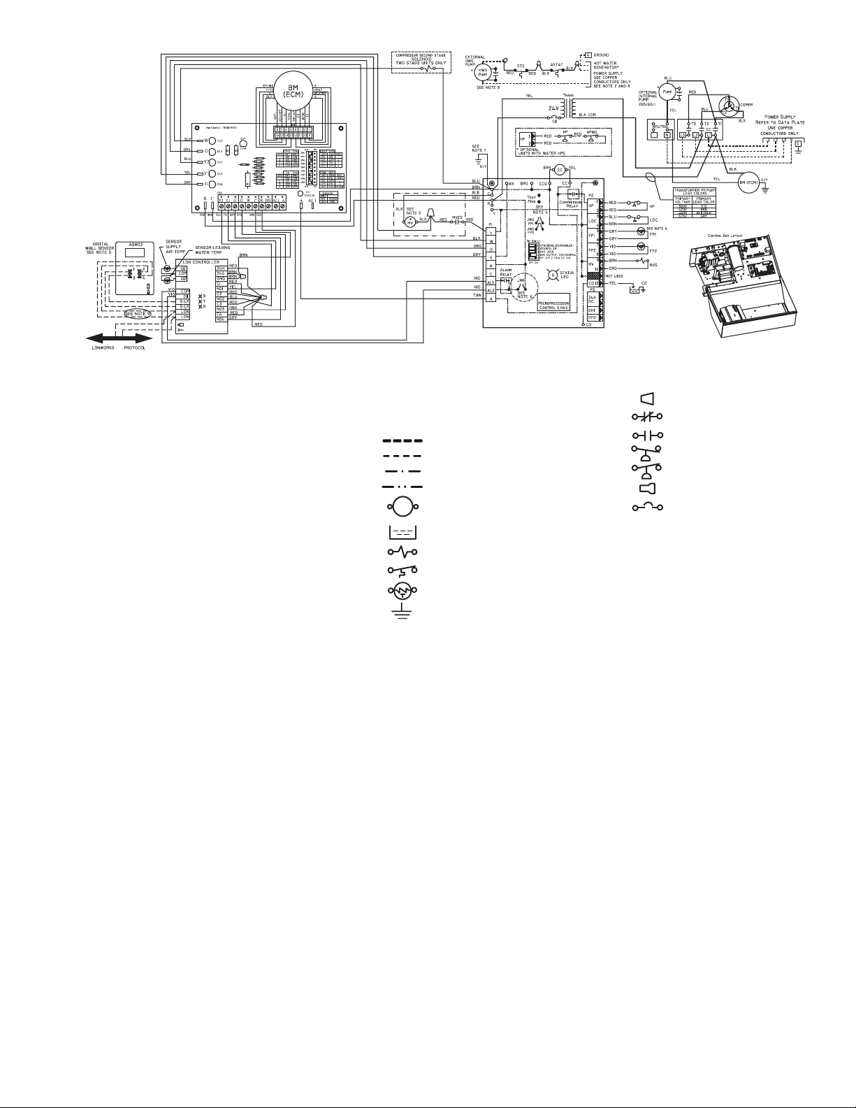
LEGEND
a50-8363
Complete C
AL — Alarm Relay Contacts
ASTAT — Aquastat
BM — Blower Motor
BMC — Blower Motor Capacitor
BR — Blower Relay
CB — Circuit Breaker
CC — Compressor Contactor
CO — Sensor, Condensate Overflow
DTS — Discharge Temperature Switch
ECM — Electronically Commutated Motor
FP1 — Sensor, Water Coil Freeze Protection
FP2 — Sensor, Air Coil Freeze Protection
HP — High-Pressure Switch
HPWS — High-Pressure Water Switch
HWG — Hot Water Generator
JW1 — Clippable Field Selection Jumper
LOC — Loss of Charge Pressure Switch
LON — Local Operating Network
MV — Motorized Valve
MVES — Motorized Valve End Switch
*Optional Wiring.
NOTES:
1. Compressor and blower motor thermally protected internally.
2. All wiring to the unit must comply with NEC and local codes.
3. Transformer is wired to 460 v (BLK/RED) lead for 460/3/60
units. Transformer is energy limiting or may have circuit
breaker.
4. FP1 thermistor provides freeze protection for water. When
using antifreeze solutions, cut JW3 jumper.
5. Typical thermostat wiring shown. Refer to thermostat installation instructions for wiring to the unit. Thermostat wiring must
be Class 1 and voltage rating equal to or greater than unit supply voltage.
6. Factory cut JW1 jumper. Dry contact will be available between
AL1 and AL2.
7. Transformer secondary ground via Complete C board standoffs
and screws to control box. (Ground available from top two
standoffs as shown.)
NEC — National Electrical Code
P1 — Field Wiring Terminal Block
RVS — Reversing Valve Solenoid
TRANS — Transformer
Wire Nut
Relay Contacts - N.C.
Field Line Voltage Wiring
Field Low Voltage Wiring
Printed Circuit Trace
Optional Wiring
Relay/Contactor Coil
Condensate Pan
Solenoid Coil
Temperature Switch
Thermistor
Ground
8. Aquastat is supplied with unit and must be wired in series with
the hot leg to the pump. Aquastat is rated for voltages up to
277-v.
9. Optional LON wires. Only connect if LON connection is desired
at the wall sensor.
10. Fan motors are factory wired for medium speed. For high or low
speed, remove BLU wire from fan motor speed tap “M” and
connect to “H” for high speed or “L” for low speed.
11. For low speed, remove BLK wire from BR “6” and replace with
RED. Connect BLK and BRN wires together.
12. For blower motors with leads. For medium or low speed,
disconnect BLK wire from BR “6”. Connect BLK and ORG/PUR
wire together. Connect RED for low or BLU for medium to
BR “6”.
13. The 460-v units using an ECM (electronically commutated
motor) fan motor, modulating HWR (hot water reheat), and/or
an internal secondary pump will require a neutral wire from the
supply side in order to feed the accessory with 265-v.
Relay Contacts - N.O.
Low Pressure Switch
High Pressure Switch
Splice Cap
Circuit Breaker
Fig 18 — Units with ECM, Complete C and LON Controller (460 V)
17
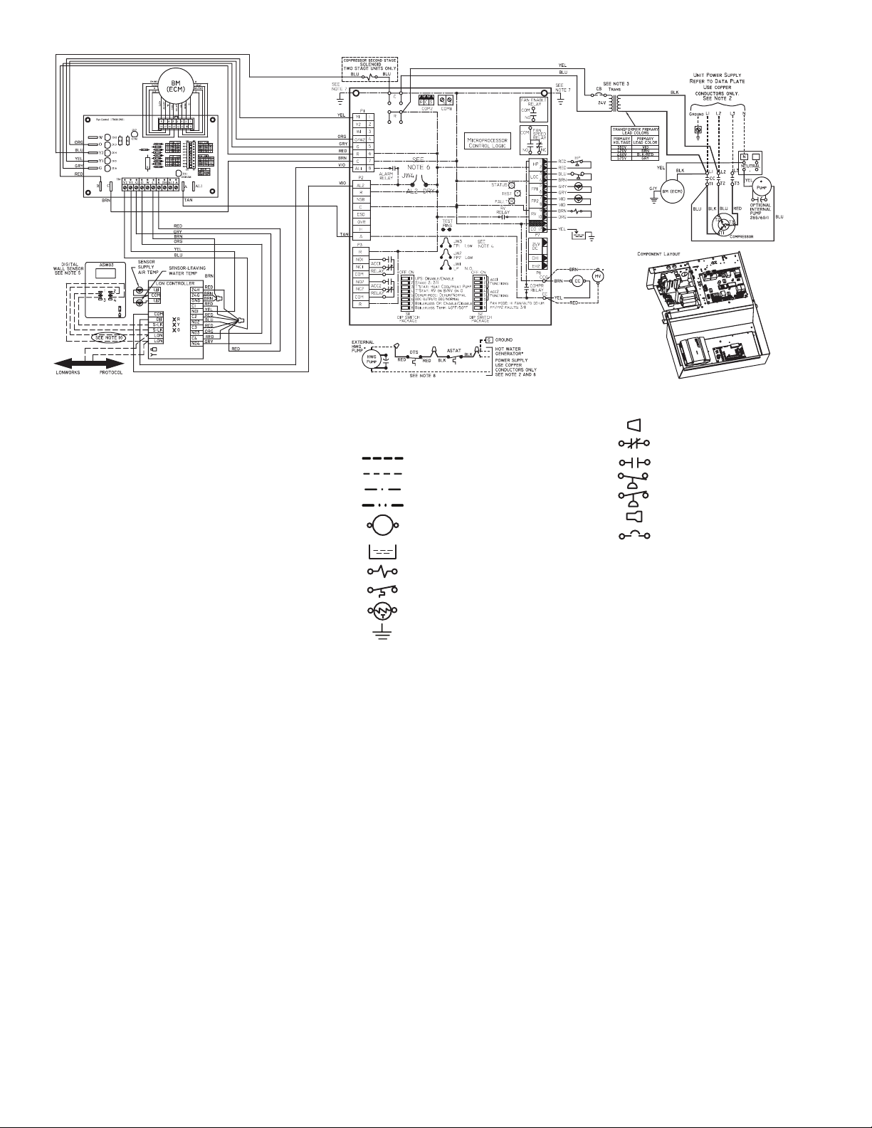
LEGEND
Deluxe D
HP
LOC
SEE NOTE 4
FP1
FP2
RVS
CO
a50-8364
AL — Alarm Relay Contacts
ASTAT — Aquastat
BM — Blower Motor
BMC — Blower Motor Capacitor
BR — Blower Relay
CB — Circuit Breaker
CC — Compressor Contactor
CO — Sensor, Condensate Overflow
DTS — Discharge Temperature Switch
ECM — Electronically Commutated Motor
FP1 — Sensor, Water Coil Freeze Protection
FP2 — Sensor, Air Coil Freeze Protection
HP — High-Pressure Switch
HPWS — High-Pressure Water Switch
HWG — Hot Water Generator
JW1 — Clippable Field Selection Jumper
LOC — Loss of Charge Pressure Switch
LON — Local Operating Network
MV — Motorized Valve
NEC — National Electrical Code
P1 — Field Wiring Terminal Block
RVS — Reversing Valve Solenoid
TRANS — Transformer
*Optional Wiring.
NOTES:
1. Compressor and blower motor thermally protected internally.
2. All wiring to the unit must comply with NEC and local codes.
3. Transformer is wired to 460 v (BLK/RED) lead for 460/3/60
units. Transformer is energy limiting or may have circuit
breaker.
4. FP1 thermistor provides freeze protection for water. When
using antifreeze solutions, cut JW3 jumper.
5. Typical thermostat wiring shown. Refer to thermostat installation instructions for wiring to the unit. Thermostat wiring must
be Class 1 and voltage rating equal to or greater than unit supply voltage.
6. Factory cut JW1 jumper. Dry contact will be available between
AL1 and AL2.
7. Transformer secondary ground via Deluxe D board standoffs
and screws to control box. (Ground available from top two
standoffs as shown.)
Wire Nut
Relay Contacts - N.C.
Field Line Voltage Wiring
Field Low Voltage Wiring
Printed Circuit Trace
Optional Wiring
Relay/Contactor Coil
Relay Contacts - N.O.
Low Pressure Switch
High Pressure Switch
Splice Cap
Circuit Breaker
Condensate Pan
Solenoid Coil
Temperature Switch
Thermistor
Ground
8. Aquastat is supplied with unit and must be wired in series with
the hot leg to the pump. Aquastat is rated for voltages up to
277-v.
9. Blower motor is factory wired for medium and high speeds. For
any other combination of speeds, at the motor attach the BLK
wire to the higher of the two desired speed taps and the BLU
wire to the lower of the two desired speed taps.
10. Optional LON wires. Only connect if LON connection is desired
at the wall sensor.
11. Blower motor is factory wired for high and low speeds. No other
combination is available.
12. The 460-v units using an ECM (electronically commutated
motor) fan motor, modulating HWR (hot water reheat), and/or
an internal secondary pump will require a neutral wire from the
supply side in order to feed the accessory with 265-v.
Fig 19 — Units with ECM, Deluxe D and LON Controller (460 V)
18
LEGEND
a50-8232
AL — Alarm Relay Contacts
ASTAT — Aquastat
BM — Blower Motor
BR — Blower Relay
CB — Circuit Breaker
CC — Compressor Contactor
CO — Sensor, Condensate Overflow
CR — Cooling Relay
DTS — Discharge Temp Switch
ECM — Electronically Commuted Motor
FP1 — Sensor, Water Coil Freeze Protection
FP2 — Sensor, Air Coil Freeze Protection
HP — High Pressure Switch
HPWS — High Pressure Water Switch
HWG — Hot Water Generator
JW — Jumper Wire
LOC — Loss of Charge Pressure Switch
LWT — Leaving Water Temperature
MV — Motorized Valve
MVES — Motorized Valve End Switch
P1 — Field Wiring Terminal Block
RVS — Reversing Valve Solenoid
SAT — Saturated Air Temperature
TRANS — Transformer
UPS — Unit Performance Sentinel
*Optional Wiring.
NOTES:
1. Compressor and blower motor thermally protected internally.
2. All wiring to the unit must comply with NEC and local codes.
3. 208-240 60 Hz units are wired for 208v operation. Transformer is energy
limiting or may have circuit breaker.
4. FP1 thermistor provides low temperature protection for water. When
using antifreeze solutions, cut JW3 jumper.
5. Refer to multiple protocol controller (MPC), LON, or TSTAT Installation,
Application, and Operation Manual for control wiring to the wire from
PremierLink controller to “Y” Complete C when motorized valve is not
used. Thermostat wiring must be “Class 1” and voltage rating equal to or
greater than unit supply voltage.
6. 24v alarm signal shown. For dry contact, cut JW1 jumper and dry contact will be available between AL1 and AL2.
7. Transformer secondary ground via green wire with yellow stripe from “C”
terminal to control box.
8. Aquastat is supplied with unit and must be wired in series with the hot
leg to the pump. Aquastat is rated for voltages up to 277v.
Thermistor
Ground
Field Line Voltage Wiring
Field Low Voltage Wiring
Field Line Voltage Wiring
Field Low Voltage Wiring
Printed Circuit Trace
Optional Wiring
Relay/Contactor Coil
Condensate Pan
Solenoid Coil
Temperature Switch
COMPLETE C CONTROLLER FAULT CODES
DESCRIPTION OF OPERATION LED ALARM RELAY
Normal Mode ON Open
Normal Mode with UPS Warning ON
Complete C is Non-Functional OFF Open
Fault Retry Slow Flash Open
Lockout Fast Flash Closed
Over/Under Voltage Shutdown Slow Flash Open (Closed After 15 Min.)
Test Mode-No Fault in Memory Flashing Code 1 Cycling Code 1
Test Mode-HP Fault in Memory Flashing Code 2 Cycling Code 2
Test Mode-LP Fault in Memory Flashing Code 3 Cycling Code 3
Test Mode-FP1 Fault in Memory Flashing Code 4 Cycling Code 4
Test Mode-FP2 Fault in Memory Flashing Code 5 Cycling Code 5
Test Mode-CO Fault in Memory Flashing Code 6 Cycling Code 6
Test Mode-Over/Under Shutdown
in Memory
Test Mode-UPS in Memory Flashing Code 8 Cycling Code 8
Swapped FP1/FP2 Lockout Flashing Code 9 Cycling Code 9
Flashing Code 7 Cycling Code 7
Wire Nut
Relay Contacts - N.C.
Relay Contacts - N.O.
Low Pressure Switch
High Pressure Switch
Splice Cap
Circuit Breaker
Capacitor
G
LED
Cycle (Closed 5 Sec.
Open 25 Sec.)
Fig. 20 — Units with Complete C and Premierlink™ Controller, Single-Phase (208/230 V)
19
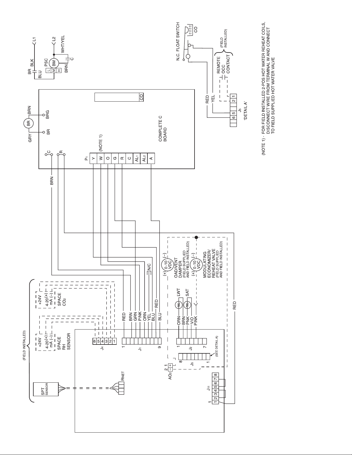
Fig. 21 — Units with Complete C and WSHP Open Multiple Protocol Controls
WHSP-OPEN
A50-8355
20
LEGEND
BM — Blower Motor
BR — Blower Relay
CO — Condensate Overflow
LWT — Leaving Water Temperature
N.C. — Normally Closed
OAD — Outside Air Damper
OCC — Occupancy Input Contact
RH — Relative Humidity
SAT — Supply Air Temperature
SPT — Space Temperature
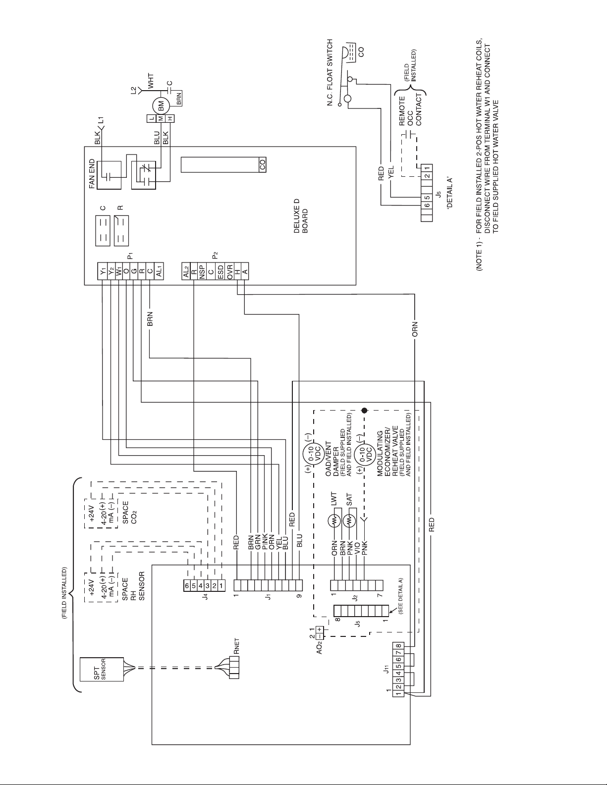
Fig. 22 — Units with Deluxe D and WSHP Open Multiple Protocol Controls
WSHP-OPEN
A50-8354
21
LEGEND
BM — Blower Motor
CO — Condensate Overflow
LWT — Leaving Water Temperature
N.C. — Normally Closed
OAD — Outside Air Damper
OCC — Occupancy Input Contact
RH — Relative Humidity
SAT — Supply Air Temperature
SPT — Space Temperature
 Loading...