


Models 750/751/754/774/794
Soft Serve Freezers
Operating Instructions
028754-M
2/01/02

Complete this page for quick reference when service is required:
Taylor Distributor:
Address:
Phone:
Service:
Parts:
Date of Installation:
Information found on the data label:
Model Number:
Serial Number:
Electrical Specs: Voltage |
|
Cycle |
|||||
Phase |
|
|
|
|
|
||
Maximum Fuse Size: |
|
|
|
|
A |
||
Minimum Wire Ampacity: |
|
|
|
|
A |
||
E February, 2002 Taylor All rights reserved. 028754--M
The word Taylor and the Crown design
are registered trademarks in the United States of America and certain other countries.
Taylor Company
750 N. Blackhawk Blvd.
Rockton, IL 61072

Table of Contents
Section 1 |
To the Installer . . . . . . . . . . . . . . . . . . . . . . . . . . . . . . . . . . . . . . . . . . . . |
1 |
Water Connections (Water Cooled Units Only) . . . . . . . . . . . . . . . . . . . . . . . . . . . . |
1 |
|
Air Cooled Units . . . . . . . . . . . . . . . . . . . . . . . . . . . . . . . . . . . . . . . . . . . . . . . . . . . . . . . |
1 |
|
Electrical Connections . . . . . . . . . . . . . . . . . . . . . . . . . . . . . . . . . . . . . . . . . . . . . . . . . |
1 |
|
Section 2 |
To the Operator . . . . . . . . . . . . . . . . . . . . . . . . . . . . . . . . . . . . . . . . . . . |
2 |
Compressor Warranty Disclaimer . . . . . . . . . . . . . . . . . . . . . . . . . . . . . . . . . . . . . . . |
2 |
|
Section 3 |
Safety . . . . . . . . . . . . . . . . . . . . . . . . . . . . . . . . . . . . . . . . . . . . . . . . . . . . |
3 |
Section 4 |
Operator Parts Identification . . . . . . . . . . . . . . . . . . . . . . . . . . . . . . . |
4 |
Model 750 . |
. . . . . . . . . . . . . . . . . . . . . . . . . . . . . . . . . . . . . . . . . . . . . . . . . . . . . . . . . . . |
4 |
Model 751 . |
. . . . . . . . . . . . . . . . . . . . . . . . . . . . . . . . . . . . . . . . . . . . . . . . . . . . . . . . . . . |
5 |
Model 754 . |
. . . . . . . . . . . . . . . . . . . . . . . . . . . . . . . . . . . . . . . . . . . . . . . . . . . . . . . . . . . |
6 |
Model 774 . |
. . . . . . . . . . . . . . . . . . . . . . . . . . . . . . . . . . . . . . . . . . . . . . . . . . . . . . . . . . . |
7 |
Model 774 Topping Pump . . . . . . . . . . . . . . . . . . . . . . . . . . . . . . . . . . . . . . . . . . . . . . |
8 |
|
Model 794 . |
. . . . . . . . . . . . . . . . . . . . . . . . . . . . . . . . . . . . . . . . . . . . . . . . . . . . . . . . . . . |
9 |
Models 750 & 751 Single Spout Door and Beater Assembly . . . . . . . . . . . . . . . . |
10 |
|
Models 754, 774 & 794 Three Spout Door and Beater Assembly . . . . . . . . . . . . |
11 |
|
Section 5 |
Important: To the Operator . . . . . . . . . . . . . . . . . . . . . . . . . . . . . . . . . |
12 |
Symbol Definitions . . . . . . . . . . . . . . . . . . . . . . . . . . . . . . . . . . . . . . . . . . . . . . . . . . . . |
12 |
|
Power Switch . . . . . . . . . . . . . . . . . . . . . . . . . . . . . . . . . . . . . . . . . . . . . . . . . . . . . . . . . |
13 |
|
MIX LOW Indicator Light . . . . . . . . . . . . . . . . . . . . . . . . . . . . . . . . . . . . . . . . . . . . . . . |
13 |
|
MIX REF Key . . . . . . . . . . . . . . . . . . . . . . . . . . . . . . . . . . . . . . . . . . . . . . . . . . . . . . . . . |
13 |
|
STANDBY Key . . . . . . . . . . . . . . . . . . . . . . . . . . . . . . . . . . . . . . . . . . . . . . . . . . . . . . . . |
13 |
|
WASH Key |
. . . . . . . . . . . . . . . . . . . . . . . . . . . . . . . . . . . . . . . . . . . . . . . . . . . . . . . . . . . |
13 |
AUTO Key |
. . . . . . . . . . . . . . . . . . . . . . . . . . . . . . . . . . . . . . . . . . . . . . . . . . . . . . . . . . . |
13 |
Reset Button . . . . . . . . . . . . . . . . . . . . . . . . . . . . . . . . . . . . . . . . . . . . . . . . . . . . . . . . . |
14 |
|
Air Tube . . |
. . . . . . . . . . . . . . . . . . . . . . . . . . . . . . . . . . . . . . . . . . . . . . . . . . . . . . . . . . . |
14 |
Adjustable Draw Handle . . . . . . . . . . . . . . . . . . . . . . . . . . . . . . . . . . . . . . . . . . . . . . . |
14 |
|
Models 750, 751, 754, 774, 794 |
Table of Contents |
|
|

Table of Contents - Page 2
Section 6 |
Operating Procedures . . . . . . . . . . . . . . . . . . . . . . . . . . . . . . . . . . . . . |
15 |
Prior to Set-Up (Model 774) . . . . . . . . . . . . . . . . . . . . . . . . . . . . . . . . . . . . . . . . . . . . |
15 |
|
Assembly . |
. . . . . . . . . . . . . . . . . . . . . . . . . . . . . . . . . . . . . . . . . . . . . . . . . . . . . . . . . . . |
15 |
Sanitizing . |
. . . . . . . . . . . . . . . . . . . . . . . . . . . . . . . . . . . . . . . . . . . . . . . . . . . . . . . . . . . |
20 |
Priming . . . |
. . . . . . . . . . . . . . . . . . . . . . . . . . . . . . . . . . . . . . . . . . . . . . . . . . . . . . . . . . . |
22 |
Closing Procedure . . . . . . . . . . . . . . . . . . . . . . . . . . . . . . . . . . . . . . . . . . . . . . . . . . . . |
23 |
|
Draining Product From The Freezing Cylinder . . . . . . . . . . . . . . . . . . . . . . . . . . . . |
23 |
|
Rinsing . . . |
. . . . . . . . . . . . . . . . . . . . . . . . . . . . . . . . . . . . . . . . . . . . . . . . . . . . . . . . . . . |
23 |
Cleaning . . |
. . . . . . . . . . . . . . . . . . . . . . . . . . . . . . . . . . . . . . . . . . . . . . . . . . . . . . . . . . . |
23 |
Disassembly . . . . . . . . . . . . . . . . . . . . . . . . . . . . . . . . . . . . . . . . . . . . . . . . . . . . . . . . . . |
24 |
|
Brush Cleaning . . . . . . . . . . . . . . . . . . . . . . . . . . . . . . . . . . . . . . . . . . . . . . . . . . . . . . . |
24 |
|
Section 7 |
Important: Operator Checklist . . . . . . . . . . . . . . . . . . . . . . . . . . . . . . |
25 |
During Cleaning and Sanitizing . . . . . . . . . . . . . . . . . . . . . . . . . . . . . . . . . . . . . . . . . |
25 |
|
Troubleshooting Bacterial Count . . . . . . . . . . . . . . . . . . . . . . . . . . . . . . . . . . . . . . . . |
25 |
|
Regular Maintenance Checks . . . . . . . . . . . . . . . . . . . . . . . . . . . . . . . . . . . . . . . . . . . |
25 |
|
Winter Storage . . . . . . . . . . . . . . . . . . . . . . . . . . . . . . . . . . . . . . . . . . . . . . . . . . . . . . . . |
26 |
|
Section 8 |
Troubleshooting Guide . . . . . . . . . . . . . . . . . . . . . . . . . . . . . . . . . . . . |
27 |
Section 9 |
Parts Replacement Schedule . . . . . . . . . . . . . . . . . . . . . . . . . . . . . . . |
30 |
Section 10 |
Parts List . . . . . . . . . . . . . . . . . . . . . . . . . . . . . . . . . . . . . . . . . . . . . . . . . |
31 |
Wiring Diagrams . . . . . . . . . . . . . . . . . . . . . . . . . . . . . . . . . . . . . . . . . . . . . . . . . . . . . . |
42 |
|
Note: Continuing research results in steady improvements; therefore, information in this manual is subject to change without notice.
Table of Contents |
Models 750, 751, 754, 774, 794 |
|
|

Section 1 |
To the Installer |
This machine is designed for indoor use only.
 DO NOT install the machine in an area where a water jet could be used to clean or rinse the machine. Failure to follow this instruction may result in serious electrical shock.
Water Connections
(Water Cooled Units Only)
An adequate cold water supply must be provided with a hand shut-off valve. On the underside rear of the base pan, two 3/8” I.P.S. (for single-head units) or two 1/2” I.P.S. (for double-head units) water connections for inlet and outlet have been provided for easy hook-up. 1/2” inside diameter water lines should be connected to the machine. (Flexible lines are recommended, if local codes permit.) Depending on local water conditions, it may be advisable to install a water strainer to prevent foreign substances from clogging the automatic water valve. There will be only one water “in” and one water “out” connection for both single-head and double-head units. DO NOT install a hand shut-off valve on the water “out” line! Water should always flow in this order: first, through the automatic water valve; second, through the condenser; and third, through the outlet fitting to an open trap drain.
Air Cooled Units
The model 750 air cooled unit requires a minimum of 6” (152 mm) of clearance on both sides and 0” in the rear of the unit. The model 751, 754, 774 and 794 units require 3” on all sides. This will allow for adequate air flow across the condenser(s). Failure to allow adequate clearance can reduce the refrigeration capacity of the freezer and possibly cause permanent damage to the compressor.
Electrical Connections
Each freezer requires one power supply for each data label. Check the data label(s) on the freezer for fuse, circuit ampacity and electrical specifications. Refer to the wiring diagram provided inside of the electrical box, for proper power connections.
In the United States, this equipment is intended to be installed in accordance with the National Electrical Code (NEC), ANSI/NFPA 70--1987. The purpose of the NEC code is the practical safeguarding of persons and property from hazards arising from the use of electricity. This code contains provisions considered necessary for safety. Compliance therewith and proper maintenance will result in an installation essentially free from hazard!
In all other areas of the world, equipment should be installed in accordance with the existing local codes. Please contact your local authorities.
Stationary appliances which are not equipped with a power cord and a plug or other device to disconnect the appliance from the power source must have an all--pole disconnecting device with a contact gap of at least 3 mm installed in the external installation.
 CAUTION: THIS EQUIPMENT MUST BE PROPERLY GROUNDED! FAILURE TO DO SO CAN RESULT IN SEVERE PERSONAL INJURY FROM ELECTRICAL SHOCK!
Beater rotation must be clockwise as viewed looking into the freezing cylinder of any model freezer.
 Note: The following procedures should be performed by a trained service technician.
To correct rotation on a three-phase unit, interchange any two incoming power supply lines at freezer main terminal block only.
To correct rotation on a single-phase unit, change the leads inside the beater motor. (Follow diagram printed on motor.)
Electrical connections are made directly to the terminal block provided in the main control box located under the upper left side panel on the Model 750, or
|
|
050418 |
|
|
|
Models 750, 751, 754, 774, 794 |
1 |
To the Installer |
|
|
|

Section 2 |
To the Operator |
|
|
The freezer you have purchased has been carefully engineered and manufactured to give you dependable operation. The Taylor Company soft-serve models covered in this manual consist of the following: 750, 751, 754, 774, and 794.
These units, when properly operated and cared for, will produce a consistent quality product. Like all mechanical products, they will require cleaning and maintenance. A minimum amount of care and attention is necessary if the operating procedures outlined in this manual are followed closely.
This Operator’s Manual should be read before operating or performing any maintenance on your equipment.
Your Taylor freezer will NOT eventually compensate for and correct any errors during the set-up or filling operations. Thus, the initial assembly and priming procedures are of extreme importance. It is strongly recommended that personnel responsible for the equipment’s operation, both assembly and disassembly, go through these procedures together in order to be properly trained and to make sure that no confusion exists.
In the event you should require technical assistance, please contact your local authorized Taylor Distributor.
 If the crossed out wheeled bin symbol is affixed to this product, it signifies that this product is compliant with the EU Directive as well as other similar legislation in effect after August 13, 2005. Therefore, it must be collected separately after its use is completed, and cannot be disposed as unsorted municipal waste.
The user is responsible for returning the product to the appropriate collection facility, as specified by your local code.
For additional information regarding applicable local laws, please contact the municipal facility and/or local distributor.
Compressor Warranty Disclaimer
The refrigeration compressor(s) on this machine are warranted for the term indicated on the warranty card accompanying this machine. However, due to the Montreal Protocol and the U.S. Clean Air Act Amendments of 1990, many new refrigerants are being tested and developed, thus seeking their way into the service industry. Some of these new refrigerants are being advertised as drop-in replacements for numerous applications. It should be noted that, in the event of ordinary service to this machine’s refrigeration system, only the refrigerant specified on the affixed data label should be used. The unauthorized use of alternate refrigerants will void your compressor warranty. It will be the owner’s responsibility to make this fact known to any technician he employs.
It should also be noted that Taylor does not warrant the refrigerant used in its equipment. For example, if the refrigerant is lost during the course of ordinary service to this machine, Taylor has no obligation to either supply or provide its replacement either at billable or unbillable terms. Taylor does have the obligation to recommend a suitable replacement if the original refrigerant is banned, obsoleted, or no longer available during the five year warranty of the compressor.
The Taylor Company will continue to monitor the industry and test new alternates as they are being developed. Should a new alternate prove, through our testing, that it would be accepted as a drop-in replacement, then the above disclaimer would become null and void. To find out the current status of an alternate refrigerant as it relates to your compressor warranty, call the local Taylor Distributor or the Taylor Factory. Be prepared to provide the Model/Serial Number of the unit in question.
050818
To the Operator 2 Models 750, 751, 754, 774, 794
Section 3 |
Safety |
|
|
We at Taylor Company are concerned about the safety of the operator when he or she comes in contact with the freezer and its parts. Taylor has gone to extreme efforts to design and manufacture built-in safety features to protect both you and the service technician. As an example, warning labels have been attached to the freezer to further point out safety precautions to the operator.
 IMPORTANT -- Failure to adhere to the following safety precautions may result in severe personal injury. Failure to comply with these warnings may also damage the machine and its components. Component damage will result in part replacement expense and service repair expense.
To Operate Safely:
 DO NOT operate the freezer without reading this operator’s manual. Failure to follow this instruction may result in equipment damage, poor freezer performance, health hazards, or personal injury.
SDO NOT operate the freezer unless it is properly grounded.
SDO NOT attempt any repairs unless the main power supply to the freezer has been disconnected.
SDO NOT operate the freezer with larger fuses than specified on the freezer data label.
Failure to follow these instructions may result in electrocution or damage to the machine. Contact your local authorized Taylor Distributor for service.
 DO NOT use a water jet to clean or rinse the freezer. Failure to follow this instruction may result in serious electrical shock.
SDO NOT allow untrained personnel to operate this machine.
SDO NOT operate the freezer unless all service panels and access doors are restrained with screws.
SDO NOT remove the door, beater and blades, or drive shaft unless all control switches are in the OFF position.
SDO NOT put objects or fingers in door spout.
Failure to follow these instructions may result in contaminated product or severe personal injury to fingers or hands from hazardous moving parts.
 USE EXTREME CAUTION when removing the beater assembly. The scraper blades are very sharp and may cause injury.
 This freezer must be placed on a level surface. Failure to comply may result in personal injury or equipment damage.
DO NOT obstruct air intake and discharge openings:
Counter Model: 6” (152 mm) minimum air space on both sides and 0” on the rear.
Console Models: 3” (76 mm) minimum air space on all sides.
Failure to follow this instruction may cause poor freezer performance and damage to the machine.
These freezers are designed to operate indoors, under normal ambient temperatures of 70_--75_F (21_--24_C). The freezers have successfully performed in high ambient temperatures of 104_F (40_C) at reduced capacities.
NOISE LEVEL: Airborne noise emission does not exceed 78 dB(A) when measured at a distance of 1.0 meter from the surface of the machine and at a height of 1.6 meters from the floor.
|
|
050418 |
|
|
|
Models 750, 751, 754, 774, 794 |
3 |
Safety |
|
|
|
Section 4 Operator Parts Identification
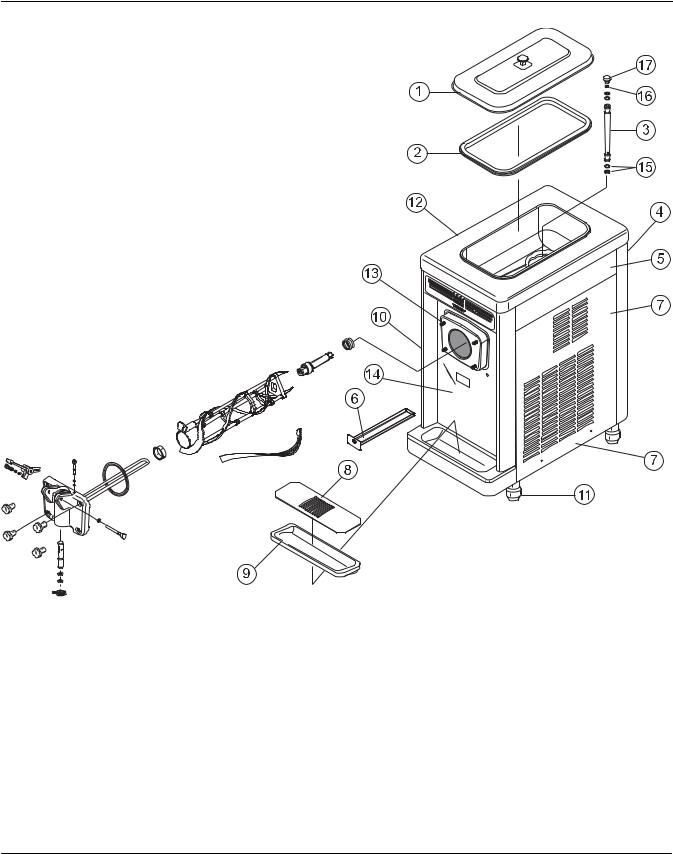
Model 750
Item |
Description |
Part No. |
|
|
|
1 |
Cover A.-Hopper |
X38458 |
|
|
|
2 |
Gasket-Hopper Cover |
038375 |
|
|
|
3 |
Tube A.-Feed |
X29429-2 |
|
|
|
4 |
Panel-Rear |
020891 |
|
|
|
5 |
Panel-Upper Side Right |
042317 |
|
|
|
6 |
Pan-Drip |
050766 |
|
|
|
7 |
Panel-Right Side |
050742 |
|
|
|
8 |
Shield-Splash |
022763 |
|
|
|
9 |
Tray-Drip |
013690 |
|
|
|
Item |
Description |
Part No. |
|
|
|
10 |
Panel-Side Left |
050741 |
|
|
|
11 |
Leg-4” SS w/O-Ring |
013458 |
|
|
|
12 |
Louver-Side-Left |
013631 |
|
|
|
13 |
Stud-Nose Cone |
022822 |
|
|
|
14 |
Panel A.-Front |
X50754 |
|
|
|
15 |
O-Ring-.643 OD x .077 W |
018572 |
|
|
|
16 |
O-Ring-3/8 OD x .070 W |
016137 |
|
|
|
17 |
Orifice |
022465-100 |
|
|
|
Operator Parts Identification |
4 |
Models 750, 751, 754, 774, 794 |
|
|
|
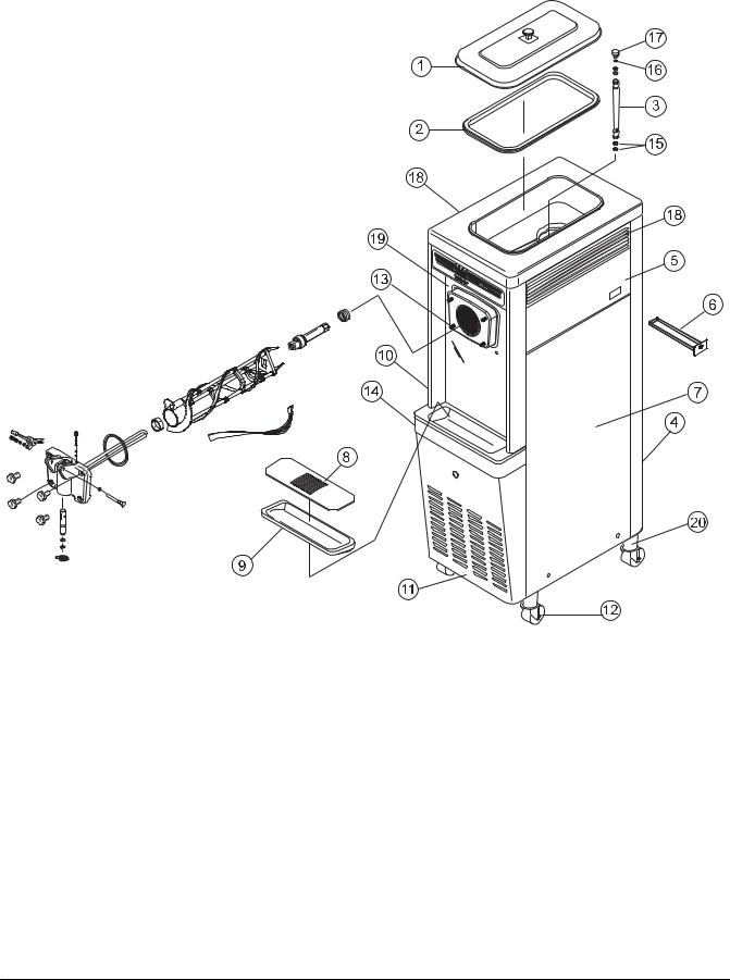
Model 751
Item |
Description |
Part No. |
|
|
|
1 |
Cover A.-Hopper |
X38458 |
|
|
|
2 |
Gasket-Hopper Cover |
038375 |
|
|
|
3 |
Tube A.-Feed |
X29429-2 |
|
|
|
4 |
Panel-Rear |
013637 |
|
|
|
5 |
Panel-Upper Side Right |
028823 |
|
|
|
6 |
Pan-Drip 11-5/8 Long |
027503 |
|
|
|
7 |
Panel A.-Lower Side Right |
X24424 |
|
|
|
8 |
Shield-Splash |
022763 |
|
|
|
9 |
Tray-Drip 14-7/8 x 5-1/8 |
013690 |
|
|
|
10 |
Panel-Upper Side Left |
024426 |
|
|
|
Item |
Description |
Part No. |
|
|
|
11 |
Panel-Service |
047170 |
|
|
|
12 |
Caster-Swivel |
018794 |
|
|
|
13 |
Stud-Nose Cone |
022822 |
|
|
|
14 |
Panel A.-Side-Lower-Louvered |
X39075 |
|
|
|
15 |
O-Ring-.643 OD x .077 W |
018572 |
|
|
|
16 |
O-Ring-3/8 OD x .070 W |
016137 |
|
|
|
17 |
Orifice |
022465-100 |
|
|
|
18 |
Louver-Side (Left & Right) |
017471 |
|
|
|
19 |
Panel A.-Front |
X33237 |
|
|
|
20 |
Adaptor A.-Caster |
X18915 |
|
|
|
Models 750, 751, 754, 774, 794 |
5 |
Operator Parts Identification |
|
|
|
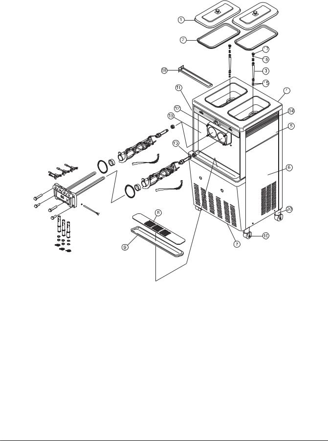
Model 754
Item |
Description |
Part No. |
|
|
|
1 |
Cover A.-Hopper |
X38458 |
|
|
|
2 |
Gasket-Hopper Cover |
038474 |
|
|
|
3 |
Tube A.-Feed |
X29429-2 |
|
|
|
4 |
Panel-Rear |
053782 |
|
|
|
5 |
Panel-Upper Side Right |
028823 |
|
|
|
6 |
Panel A.-Side Lower Right |
X46448 |
|
|
|
7 |
Panel-Service |
046584 |
|
|
|
8 |
Shield-Splash |
022766 |
|
|
|
9 |
Tray-Drip |
014533 |
|
|
|
10 |
Caster-Swivel |
018794 |
|
|
|
Item |
Description |
Part No. |
|
|
|
11 |
Panel-Upper Side Left |
028822 |
|
|
|
12 |
Stud-Nose Cone |
022822 |
|
|
|
13 |
Panel A.-Side Lower Left |
X46447 |
|
|
|
14 |
Louver-Side (Left & Right) |
017471 |
|
|
|
15 |
O-Ring-.643 OD x .077 W |
018572 |
|
|
|
16 |
O-Ring-3/8 OD x .070 W |
016137 |
|
|
|
17 |
Orifice |
022465-100 |
|
|
|
18 |
Pan-Drip 17-1/4” Long |
027504 |
|
|
|
19 |
Panel A.-Front |
X32956 |
|
|
|
20 |
Adaptor A.-Caster |
X18915 |
|
|
|
Operator Parts Identification |
6 |
Models 750, 751, 754, 774, 794 |
|
|
|
Model 774
Item |
Description |
Part No. |
|
|
|
1 |
Cover A.-Hopper |
X38458 |
|
|
|
2 |
Gasket-Hopper Cover |
038474 |
|
|
|
3 |
Tube A.-Feed |
X29429-2 |
|
|
|
4 |
Panel-Upper Rear |
X42574 |
|
|
|
5 |
Panel-Upper Side Right |
028823 |
|
|
|
6 |
Panel A.-Side Lower-Right |
X46448 |
|
|
|
7 |
Panel-Service |
047077 |
|
|
|
8 |
Shield-Splash |
022766 |
|
|
|
9 |
Tray-Drip |
014533 |
|
|
|
10 |
Caster-Swivel |
018794 |
|
|
|
11 |
Panel-Upper Side Left |
028822 |
|
|
|
12 |
Pan-Drip 17-1/4” Long |
027504 |
|
|
|
13 |
Lid with Ladle 1 oz. |
036575 |
|
|
|
Item |
Description |
Part No. |
|
|
|
14 |
Pump A.-Syrup-Tan |
053794--TAN |
|
|
|
15 |
O-Ring-.643 OD x .077 W |
018572 |
|
|
|
16 |
Panel A.-Side Lower-Left |
X46447 |
|
|
|
17 |
Jar-Syrup-Plastic |
036573 |
|
|
|
18 |
Jar-Syrup-Stainless-Shallow |
036574 |
|
|
|
19 |
Stud-Nose Cone |
022822 |
|
|
|
20 |
Louver-Side (Left & Right) |
017471 |
|
|
|
21 |
Panel-Lower Rear |
053837 |
|
|
|
22 |
O-Ring-3/8 OD x .070 W |
016137 |
|
|
|
23 |
Orifice |
022465-100 |
|
|
|
24 |
Panel A.-Front |
X42539 |
|
|
|
25 |
Adaptor A.-Caster |
X18915 |
|
|
|
Models 750, 751, 754, 774, 794 |
7 |
Operator Parts Identification |
|
|
|
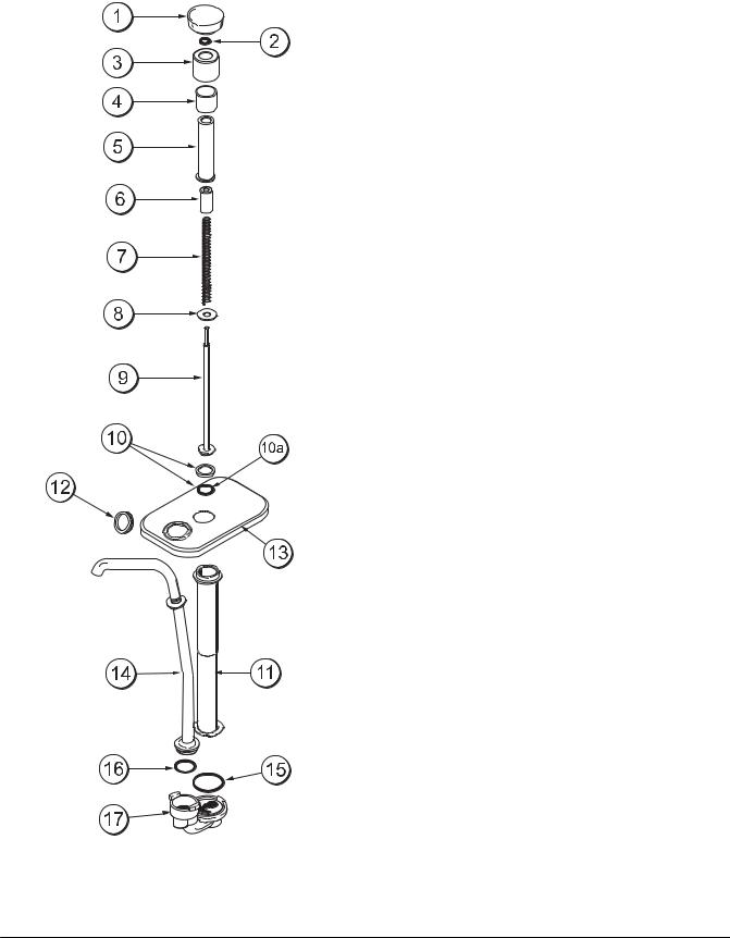
Model 774 Topping Pump (053794-)
ITEM |
DESCRIPTION |
PART NO. |
|
|
|
1 |
Knob-Plunger-Tan |
032762-TAN |
|
|
|
1 |
Knob-Plunger-Brown |
032762-BRN |
|
|
|
1 |
Knob-Plunger-Red |
032762-RED |
|
|
|
2 |
O-Ring-9/16 OD x .103 W |
016369 |
|
|
|
3 |
Nut-Plunger |
036577 |
|
|
|
4 |
Collar-Gaging 1/2 Ounce |
035514 |
|
|
|
5 |
Tube-Plunger |
032757 |
|
|
|
6 |
Insert-Plunger |
032758 |
|
|
|
7 |
Spring-Plunger |
032761 |
|
|
|
8 |
Washer-Nylon |
032760 |
|
|
|
9 |
Plunger |
036578 |
|
|
|
10 |
Seal Assembly |
X33057 |
|
|
|
10a |
O-Ring-13/16 OD x .103 W |
019330 |
|
|
|
11 |
Body-Syrup Pump |
047934 |
|
|
|
12 |
Nut-Spout |
036821 |
|
|
|
13 |
Lid-Pump |
036822 |
|
|
|
14 |
Tube-Discharge |
050912 |
|
|
|
15 |
O-Ring-1-5/16 OD x .103 W |
048149 |
|
|
|
16 |
O-Ring-1 OD x .103 W |
048148 |
|
|
|
17 |
Kit-Valve-Captured Ball Shallow |
048166-001 |
|
|
|
|
Includes: |
|
|
|
|
|
1 - Body A.-Pump Valve |
|
|
|
|
|
1 - O-Ring-1-5/16 OD x .103W (048149) |
|
|
|
|
|
1 - Brush-cleaning (054068) |
|
|
|
|
|
1 - Instruction Sheet-Installation/Cleaning |
|
|
|
|
Operator Parts Identification |
8 |
Models 750, 751, 754, 774, 794 |
|
|
|
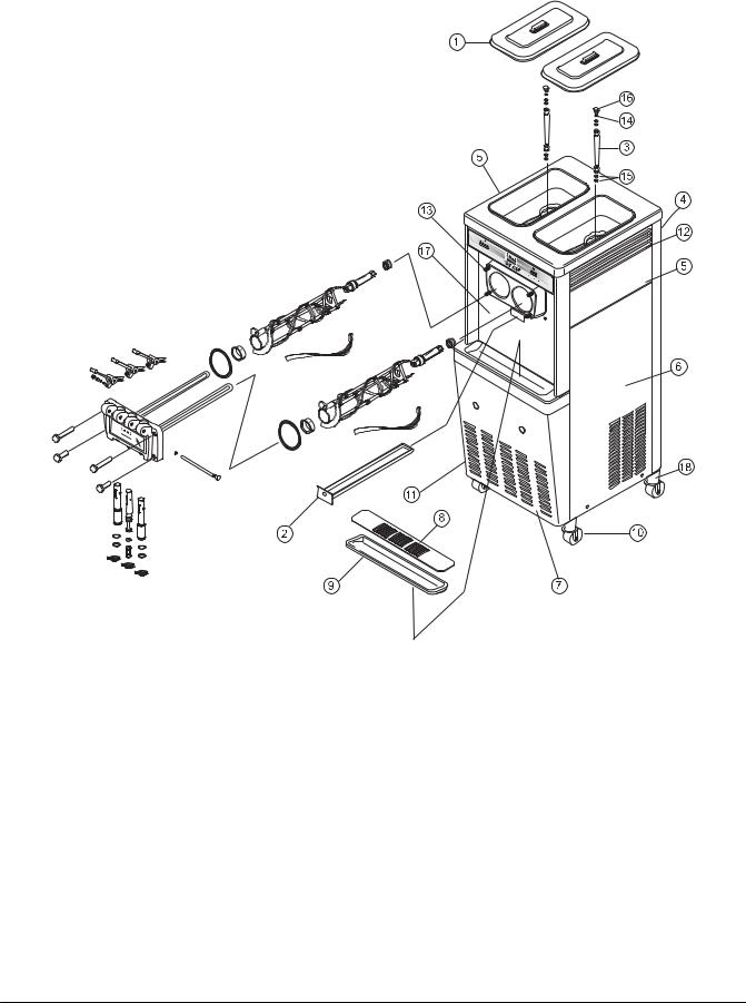
Model 794
Item |
Description |
Part No. |
|
|
|
1 |
Cover-Hopper 14 Qt. Grey |
041682-GRY |
|
|
|
2 |
Pan-Drip 19-1/2 Long |
035034 |
|
|
|
3 |
Tube A.-Feed |
X29429-2 |
|
|
|
4 |
Panel-Rear |
041855 |
|
|
|
5 |
Panel-Upper Side (Left & Right) |
024426 |
|
|
|
6 |
Panel A.-Side Lower Right |
X46448 |
|
|
|
7 |
Panel-Service |
041856 |
|
|
|
8 |
Shield-Splash |
022765 |
|
|
|
9 |
Tray-Drip |
020157 |
|
|
|
Item |
Description |
Part No. |
|
|
|
10 |
Caster |
018794 |
|
|
|
11 |
Panel A.-Side Lower Left |
X46447 |
|
|
|
12 |
Louver-Side (Left & Right) |
017471 |
|
|
|
13 |
Stud-Nose Cone |
022822 |
|
|
|
14 |
O-Ring-3/8 OD x .070 W |
016137 |
|
|
|
15 |
O-Ring-.643 OD x .077 W |
018572 |
|
|
|
16 |
Orifice |
024465-100 |
|
|
|
17 |
Panel A.-Front |
X41820 |
|
|
|
18 |
Adaptor A.-Caster |
X18915 |
|
|
|
Models 750, 751, 754, 774, 794 |
9 |
Operator Parts Identification |
|
|
|
Models 750 & 751 Single Spout Door and Beater Assembly
ITEM |
DESCRIPTION |
PART NO. |
|
|
|
1 |
HANDLE A.- DRAW |
X55096 |
|
|
|
1a |
DRAW HANDLE |
028804 |
|
|
|
1b |
SCREW-ADJUST |
055092 |
|
|
|
1c |
O-RING 1/4OD X .070W |
015872 |
|
|
|
1d |
NUT-JAM |
029639-BLK |
|
|
|
2 |
NUT-STUD FLAT LONG |
021508 |
|
|
|
3 |
DOOR A.- 1-SPOUT |
X51531-10 |
|
|
|
4 |
VALVE A.- DRAW |
X18303 |
|
|
|
5 |
O-RING 7/8OD X .070W |
014402 |
|
|
|
6 |
CAP-DESIGN |
014218 |
|
|
|
ITEM |
DESCRIPTION |
PART NO. |
|
|
|
7 |
O-RING 5/16OD X .070W |
016272 |
|
|
|
8 |
PLUG-PRIME |
028805 |
|
|
|
9 |
O-RING-PRIME PLUG |
016137 |
|
|
|
10 |
PIN A.- PIVOT |
X22820 |
|
|
|
11 |
GASKET-DOOR HT 4” |
048926 |
|
|
|
12 |
BLADESCRAPER |
035174 |
|
|
|
13 |
BEATER A.- HELICORE |
X31761 |
|
|
|
14 |
BEARING-FRONT |
050216 |
|
|
|
15 |
SHAFT-BEATER |
032564 |
|
|
|
16 |
SEAL-DRIVE SHAFT |
032560 |
|
|
|
Operator Parts Identification |
10 |
Models 750, 751, 754, 774, 794 |
|
|
|

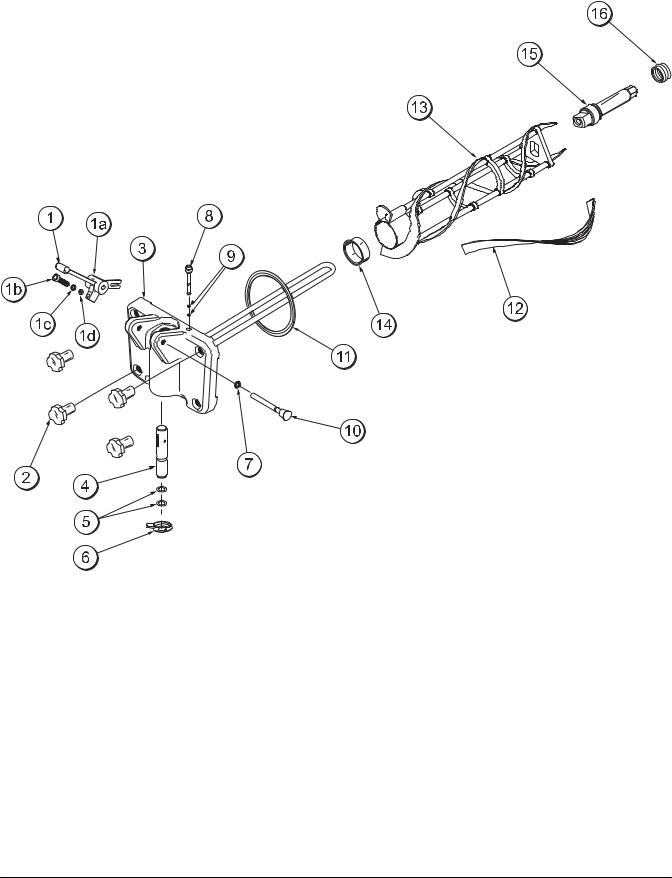
Models 754, 774 & 794 Three Spout Door and Beater Assembly
Item |
Description |
Part No. |
1 |
Handle A.-Draw |
X55096 |
1a |
Draw Handle |
028804 |
1b |
Screw-Adjustment |
055092 |
1c |
O-Ring 1/4 OD x .070 W |
015872 |
1d |
Nut--Jam |
029639--BLK |
2 |
Nut-Stud Long |
034382 |
3 |
Nut-Stud Short |
034383 |
4 |
Valve A.-Draw |
X18303 |
5 |
O-Ring 7/8 OD x .070 W |
014402 |
6 |
Shaft-Beater |
032564 |
Item |
Description |
Part No. |
7 |
Seal-Drive Shaft |
032560 |
8 |
Cap-Design |
014218 |
9 |
Decal-Door |
021521 |
10 |
Door A.-3 Spout |
X51532-12 |
11 |
Rod A.-Pivot |
X20683 |
12 |
O-Ring 5/16 OD x .070 W |
016272 |
13 |
Gasket-Door HT 4” |
048926 |
14 |
Bearing-Front |
050216 |
15 |
Beater A.-Helicore |
X31761 |
16 |
Blade-Scraper |
035174 |
Models 750, 751, 754, 774, 794 |
11 |
Operator Parts Identification |
|
|
|
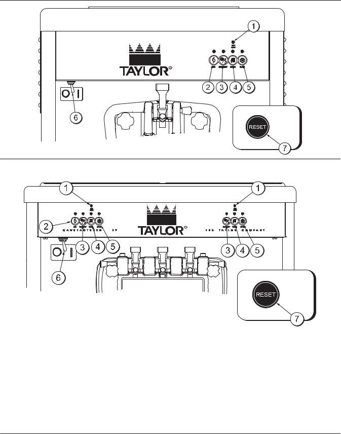
Section 5 |
Important: To the Operator |
750/751 |
|
754/774/794
ITEM |
DESCRIPTION |
|
|
1 |
MIX LOW INDICATOR LIGHT |
2 |
MIX REFRIGERATION KEY |
3 |
STANDBY KEY |
4 |
WASH KEY |
5 |
AUTO KEY |
6 |
POWER ON/OFF (TOGGLE) |
7 |
RESET BUTTON |
Symbol Definitions
To better communicate in the International arena, the words on many of our operator switches and keys have been replaced with symbols to indicate their functions. Your Taylor equipment is designed with these International symbols.
Important: To the Operator |
12 |
Models 750, 751, 754, 774, 794 |
|
|
|

The following chart identifies the symbol definitions.
= OFF
= ON
= MIX
= STANDBY
= WASH
= AUTO
Power Switch
When placed in the ON position, the power switch allows SOFTECH control panel operation.
MIX LOW Indicator Light
Located on the front of the machine is a mix level indicating light. When the light is flashing, it indicates that the mix hopper has a low supply of mix and should be refilled as soon as possible. Always maintain at least 3” (7.6 cm) of mix in the hopper. If you neglect to add mix, a freeze-up may occur. This will cause eventual damage to the beater, blades, drive shaft, and freezer door.
MIX REF Key
When the MIX REF key is pressed, the light comes on indicating the mix hopper refrigeration system is operating. For the Models 754, 774, and 794 the MIX REF is controlled by the left side of the freezer as viewed from the operator end. The MIX REF function cannot be cancelled unless the AUTO or STANDBY modes are cancelled first.
STANDBY Key
The Separate Hopper Refrigeration System (SHR) and the Cylinder Temperature Retention System (CTR) are standard features on these machines. The SHR incorporates the use of a separate small refrigeration system to maintain the mix in the hopper below 40_(4.4_C) to assure bacteria control. The CTR works with the SHR to maintain a good quality product. During long “No Sale” periods, it is necessary to warm the product in the freezing cylinder to approximately 35_F to 40_F (1.7_C to 4.4_C) to prevent overbeating and product breakdown.
To activate the SHR and CTR, press the STANDBY key. Remove the air orifice and place the air tube (end without the hole) into the mix inlet hole.
When the STANDBY key is pressed, the light comes on, indicating the CTR (Cylinder Temperature Retention System) has been activated. In the STANDBY mode, the WASH and AUTO functions are automatically cancelled. The MIX REF function is automatically locked in to maintain the mix in the hopper.
To resume normal operation, press the AUTO key. When the unit cycles off, the product in the freezing cylinder will be at serving viscosity. At this time, place the air tube (end with the hole) into the mix inlet hole and install the air orifice.
WASH Key
When the WASH key is pressed, the light comes on. This indicates beater motor operation. The STANDBY or AUTO modes must be cancelled first to activate the WASH mode.
AUTO Key
When the AUTO key is pressed, the light comes on. This indicates that the main refrigeration system has been activated. In the AUTO mode, the WASH or STANDBY functions are automatically cancelled. The MIX REF function is automatically locked in to maintain the mix in the mix hopper.
Note: An indicating light and an audible tone will sound whenever a mode of operation has been pressed. To cancel any function, press the key again. The light and mode of operation will shut off.
Models 750, 751, 754, 774, 794 |
13 |
Important: To the Operator |
|
|
|
 Loading...