


Diesel Generator Set
r
OPERATION AND SERVICE for
69UG15 Generator Set Units PID UG1450 and Higher
T--343 Rev --

OPERATION AND SERVICE MANUAL DIESEL DRIVEN GENERATOR SET
MODEL 69UG15
|
|
TABLE OF CONTENTS |
|
PARAGRAPH NUMBER |
Page |
||
SAFETY SUMMARY . . . . . . . . . . . . . . . . . . . . . . . . . . . . . . . . . . . . . . . . . . . . . . . . . . . . . . . . . . . . . . . . . . . . |
Safety--i |
||
GENERAL SAFETY NOTICES . . . . . . . . . . . . . . . . . . . . . . . . . . . . . . . . . . . . . . . . . . . . . . . . . . . . . . . . . . . . |
Safety--i |
||
FIRST AID . . . . . . . . . . . . . . . . . . . . . . . . . . . . . . . . . . . . . . . . . . . . . . . . . . . . . . . . . . . . . . . . . . . . . . . . . . . . . |
Safety--i |
||
OPERATING PRECAUTIONS . . . . . . . . . . . . . . . . . . . . . . . . . . . . . . . . . . . . . . . . . . . . . . . . . . . . . . . . . . . . |
Safety--i |
||
MAINTENANCE PRECAUTIONS . . . . . . . . . . . . . . . . . . . . . . . . . . . . . . . . . . . . . . . . . . . . . . . . . . . . . . . . . . |
Safety--i |
||
UNIT LABEL IDENTIFICATION . . . . . . . . . . . . . . . . . . . . . . . . . . . . . . . . . . . . . . . . . . . . . . . . . . . . . . . . . . . |
Safety--i |
||
SPECIFIC WARNING AND CAUTION STATEMENTS . . . . . . . . . . . . . . . . . . . . . . . . . . . . . . . . . . . . . . . . |
Safety--i |
||
DESCRIPTION . . . . . . . . . . . . . . . . . . . . . . . . . . . . . . . . . . . . . . . . . . . . . . . . . . . . . . . . . . . . . . . . . . . . . . . . . . . . . |
. . 1--1 |
||
1.1 |
INTRODUCTION . . . . . . . . . . . . . . . . . . . . . . . . . . . . . . . . . . . . . . . . . . . . . . . . . . . . . . . . . . . . . . . . . . . . |
. 1--1 |
|
1.2 |
CONFIGURATION IDENTIFICATION . . . . . . . . . . . . . . . . . . . . . . . . . . . . . . . . . . . . . . . . . . . . . . . . . . |
. 1--1 |
|
1.3 |
ENGINE . . . . . . . . . . . . . . . . . . . . . . . . . . . . . . . . . . . . . . . . . . . . . . . . . . . . . . . . . . . . . . . . . . . . . . . . . . . . |
. 1--5 |
|
1.3.1 |
Electronic Governor Module . . . . . . . . . . . . . . . . . . . . . . . . . . . . . . . . . . . . . . . . . . . . . . . . . . . . . . . |
. 1--5 |
|
1.3.2 |
Engine Air System . . . . . . . . . . . . . . . . . . . . . . . . . . . . . . . . . . . . . . . . . . . . . . . . . . . . . . . . . . . . . . . |
. 1--5 |
|
1.3.3 Lube Oil Filter Arrangement . . . . . . . . . . . . . . . . . . . . . . . . . . . . . . . . . . . . . . . . . . . . . . . . . . . . . . . |
. 1--5 |
||
1.3.4 |
Fuel System . . . . . . . . . . . . . . . . . . . . . . . . . . . . . . . . . . . . . . . . . . . . . . . . . . . . . . . . . . . . . . . . . . . . . |
. 1--5 |
|
1.4 |
ENGINE SCREW THREADS . . . . . . . . . . . . . . . . . . . . . . . . . . . . . . . . . . . . . . . . . . . . . . . . . . . . . . . . . . |
. 1--5 |
|
1.5 |
ALTERNATING CURRENT GENERATOR . . . . . . . . . . . . . . . . . . . . . . . . . . . . . . . . . . . . . . . . . . . . . . |
. 1--5 |
|
1.5.1 |
Principle of Operation . . . . . . . . . . . . . . . . . . . . . . . . . . . . . . . . . . . . . . . . . . . . . . . . . . . . . . . . . . . . . |
. 1--5 |
|
1.5.2 Alternating Current Generator Diagram . . . . . . . . . . . . . . . . . . . . . . . . . . . . . . . . . . . . . . . . . . . . . . |
. 1--5 |
||
1.6 |
BATTERY CHARGER . . . . . . . . . . . . . . . . . . . . . . . . . . . . . . . . . . . . . . . . . . . . . . . . . . . . . . . . . . . . . . . . |
. 1--6 |
|
1.7 |
OPERATING CONTROLS AND INSTRUMENTS . . . . . . . . . . . . . . . . . . . . . . . . . . . . . . . . . . . . . . . . |
. 1--6 |
|
1.7.1 |
Introduction . . . . . . . . . . . . . . . . . . . . . . . . . . . . . . . . . . . . . . . . . . . . . . . . . . . . . . . . . . . . . . . . . . . . . |
. 1--6 |
|
1.7.2 Control Panel and Related Components . . . . . . . . . . . . . . . . . . . . . . . . . . . . . . . . . . . . . . . . . . . . . |
. 1--6 |
||
1.8 |
SAFETY DEVICES . . . . . . . . . . . . . . . . . . . . . . . . . . . . . . . . . . . . . . . . . . . . . . . . . . . . . . . . . . . . . . . . . . |
. 1--7 |
|
1.9 |
UNIT SPECIFICATIONS . . . . . . . . . . . . . . . . . . . . . . . . . . . . . . . . . . . . . . . . . . . . . . . . . . . . . . . . . . . . . . |
. 1--11 |
|
1.10 |
ENGINE DATA . . . . . . . . . . . . . . . . . . . . . . . . . . . . . . . . . . . . . . . . . . . . . . . . . . . . . . . . . . . . . . . . . . . . . . |
. 1--11 |
|
OPERATION |
. . . . . . . . . . . . . . . . . . . . . . . . . . . . . . . . . . . . . . . . . . . . . . . . . . . . . . . . . . . . . . . . . . . . . . . . . . . . . . . . |
. 2--1 |
|
2.1 |
GENERATOR SET INSTALLATION . . . . . . . . . . . . . . . . . . . . . . . . . . . . . . . . . . . . . . . . . . . . . . . . . . . . |
. 2--1 |
|
2.2 |
GENERATOR SET REMOVAL . . . . . . . . . . . . . . . . . . . . . . . . . . . . . . . . . . . . . . . . . . . . . . . . . . . . . . . . |
. 2--2 |
|
2.3 |
STARTING AND STOPPING INSTRUCTIONS . . . . . . . . . . . . . . . . . . . . . . . . . . . . . . . . . . . . . . . . . . |
. 2--3 |
|
2.3.1 |
Pre-Start Inspection . . . . . . . . . . . . . . . . . . . . . . . . . . . . . . . . . . . . . . . . . . . . . . . . . . . . . . . . . . . . . . |
. 2--3 |
|
2.3.2 |
Starting Instructions . . . . . . . . . . . . . . . . . . . . . . . . . . . . . . . . . . . . . . . . . . . . . . . . . . . . . . . . . . . . . . |
. 2--3 |
|
2.3.3 |
Post-Start Inspection . . . . . . . . . . . . . . . . . . . . . . . . . . . . . . . . . . . . . . . . . . . . . . . . . . . . . . . . . . . . . |
. 2--3 |
|
2.3.4 |
Stopping Instructions . . . . . . . . . . . . . . . . . . . . . . . . . . . . . . . . . . . . . . . . . . . . . . . . . . . . . . . . . . . . . |
. 2--3 |
|
2.4 |
CONTROL CIRCUIT OPERATION . . . . . . . . . . . . . . . . . . . . . . . . . . . . . . . . . . . . . . . . . . . . . . . . . . . . . |
. 2--4 |
|
2.4.1 |
Sequence of Operation . . . . . . . . . . . . . . . . . . . . . . . . . . . . . . . . . . . . . . . . . . . . . . . . . . . . . . . . . . . |
. 2--4 |
|
TROUBLESHOOTING . . . . . . . . . . . . . . . . . . . . . . . . . . . . . . . . . . . . . . . . . . . . . . . . . . . . . . . . . . . . . . . . . . . . . . . . |
. 3--1 |
||
3.1 |
DIESEL ENGINE . . . . . . . . . . . . . . . . . . . . . . . . . . . . . . . . . . . . . . . . . . . . . . . . . . . . . . . . . . . . . . . . . . . . |
. 3--1 |
|
3.1.1 |
Engine Will Not Start . . . . . . . . . . . . . . . . . . . . . . . . . . . . . . . . . . . . . . . . . . . . . . . . . . . . . . . . . . . . . |
. 3--1 |
|
3.1.2 Engine Starts Then Stops . . . . . . . . . . . . . . . . . . . . . . . . . . . . . . . . . . . . . . . . . . . . . . . . . . . . . . . . . |
. 3--1 |
||
3.1.3 Engine Will Not Shut Off . . . . . . . . . . . . . . . . . . . . . . . . . . . . . . . . . . . . . . . . . . . . . . . . . . . . . . . . . . |
. 3--2 |
||
3.1.4 |
Starter Motor Malfunction . . . . . . . . . . . . . . . . . . . . . . . . . . . . . . . . . . . . . . . . . . . . . . . . . . . . . . . . . |
. 3--2 |
|
3.1.5 Malfunction In The Engine Starting Circuit . . . . . . . . . . . . . . . . . . . . . . . . . . . . . . . . . . . . . . . . . . . |
. 3--2 |
||
3.1.6 |
Miscellaneous Engine Troubleshooting . . . . . . . . . . . . . . . . . . . . . . . . . . . . . . . . . . . . . . . . . . . . . . |
. 3--3 |
|
|
|
i |
T--343 |
TABLE OF CONTENTS - Continued
PARAGRAPH NUMBER |
Page |
||
3.2 |
BATTERY CHARGER (SOLID STATE) . . . . . . . . . . . . . . . . . . . . . . . . . . . . . . . . . . . . . . . . . . . . . . . . . . |
3--3 |
|
3.3 |
ALTERNATING CURRENT GENERATOR . . . . . . . . . . . . . . . . . . . . . . . . . . . . . . . . . . . . . . . . . . . . . . . |
3--4 |
|
3.4 |
AUTO RE-START OPTION . . . . . . . . . . . . . . . . . . . . . . . . . . . . . . . . . . . . . . . . . . . . . . . . . . . . . . . . . . . . |
3--5 |
|
SERVICE AND PREVENTIVE MAINTENANCE . . . . . . . . . . . . . . . . . . . . . . . . . . . . . . . . . . . . . . . . . . . . . . . . . . . |
4--1 |
||
4.1 |
INTRODUCTION . . . . . . . . . . . . . . . . . . . . . . . . . . . . . . . . . . . . . . . . . . . . . . . . . . . . . . . . . . . . . . . . . . . . . |
4--1 |
|
4.2 |
PREVENTATIVE MAINTENANCE SCHEDULE . . . . . . . . . . . . . . . . . . . . . . . . . . . . . . . . . . . . . . . . . . . |
4--1 |
|
4.3 |
BATTERY SERVICE . . . . . . . . . . . . . . . . . . . . . . . . . . . . . . . . . . . . . . . . . . . . . . . . . . . . . . . . . . . . . . . . . . |
4--1 |
|
4.4 |
ENGINE SERVICE AND COMPONENTS . . . . . . . . . . . . . . . . . . . . . . . . . . . . . . . . . . . . . . . . . . . . . . . . |
4--1 |
|
|
4.4.1 |
Bleeding the Fuel System . . . . . . . . . . . . . . . . . . . . . . . . . . . . . . . . . . . . . . . . . . . . . . . . . . . . . . . . . . |
4--1 |
|
4.4.2 |
Servicing Fuel Pump Internal Filter . . . . . . . . . . . . . . . . . . . . . . . . . . . . . . . . . . . . . . . . . . . . . . . . . . |
4--1 |
|
4.4.3 |
Fuel Filter . . . . . . . . . . . . . . . . . . . . . . . . . . . . . . . . . . . . . . . . . . . . . . . . . . . . . . . . . . . . . . . . . . . . . . . . |
4--1 |
|
4.4.4 |
In--Line Fuel Filter . . . . . . . . . . . . . . . . . . . . . . . . . . . . . . . . . . . . . . . . . . . . . . . . . . . . . . . . . . . . . . . . . |
4--1 |
|
4.4.5 |
Cooling System . . . . . . . . . . . . . . . . . . . . . . . . . . . . . . . . . . . . . . . . . . . . . . . . . . . . . . . . . . . . . . . . . . . |
4--1 |
|
4.4.6 |
Servicing the Low Coolant Sensor . . . . . . . . . . . . . . . . . . . . . . . . . . . . . . . . . . . . . . . . . . . . . . . . . . . |
4--4 |
|
4.4.7 |
Servicing Low Oil Pressure Switch . . . . . . . . . . . . . . . . . . . . . . . . . . . . . . . . . . . . . . . . . . . . . . . . . . . |
4--4 |
|
4.4.8 |
Servicing Heater Switch . . . . . . . . . . . . . . . . . . . . . . . . . . . . . . . . . . . . . . . . . . . . . . . . . . . . . . . . . . . . |
4--4 |
|
4.4.9 |
Servicing Poly V-belt . . . . . . . . . . . . . . . . . . . . . . . . . . . . . . . . . . . . . . . . . . . . . . . . . . . . . . . . . . . . . . |
4--4 |
|
4.4.10 |
Lube Oil Filter . . . . . . . . . . . . . . . . . . . . . . . . . . . . . . . . . . . . . . . . . . . . . . . . . . . . . . . . . . . . . . . . . . . . |
4--5 |
|
4.4.11 |
Engine Speed . . . . . . . . . . . . . . . . . . . . . . . . . . . . . . . . . . . . . . . . . . . . . . . . . . . . . . . . . . . . . . . . . . . . |
4--5 |
|
4.4.12 |
Replacing the Engine Speed Sensor . . . . . . . . . . . . . . . . . . . . . . . . . . . . . . . . . . . . . . . . . . . . . . . . . |
4--5 |
|
4.4.13 |
Engine Air Cleaner . . . . . . . . . . . . . . . . . . . . . . . . . . . . . . . . . . . . . . . . . . . . . . . . . . . . . . . . . . . . . . . . |
4--5 |
|
4.4.14 |
Engine Crankcase Breather . . . . . . . . . . . . . . . . . . . . . . . . . . . . . . . . . . . . . . . . . . . . . . . . . . . . . . . . |
4--6 |
|
4.4.15 Servicing Intake Heater . . . . . . . . . . . . . . . . . . . . . . . . . . . . . . . . . . . . . . . . . . . . . . . . . . . . . . . . . . . . |
4--6 |
|
4.5 |
SERVICING THE ALTERNATING CURRENT GENERATOR . . . . . . . . . . . . . . . . . . . . . . . . . . . . . . . |
4--6 |
|
|
4.5.1 |
Preventative Maintenance and Operating Precautions . . . . . . . . . . . . . . . . . . . . . . . . . . . . . . . . . . |
4--6 |
|
4.5.2 |
Generator Repair/Test Procedures . . . . . . . . . . . . . . . . . . . . . . . . . . . . . . . . . . . . . . . . . . . . . . . . . . . |
4--7 |
|
4.5.3 |
Bearing Replacement . . . . . . . . . . . . . . . . . . . . . . . . . . . . . . . . . . . . . . . . . . . . . . . . . . . . . . . . . . . . . . |
4--8 |
|
4.5.4 |
Generator Removal and Installation . . . . . . . . . . . . . . . . . . . . . . . . . . . . . . . . . . . . . . . . . . . . . . . . . . |
4--8 |
4.6 |
GENERAL GENERATOR SET MAINTENANCE . . . . . . . . . . . . . . . . . . . . . . . . . . . . . . . . . . . . . . . . . . |
4--9 |
|
|
4.6.1 |
Maintenance Of Painted Surfaces . . . . . . . . . . . . . . . . . . . . . . . . . . . . . . . . . . . . . . . . . . . . . . . . . . . |
4--9 |
|
4.6.2 |
Check and Replace Isolators/Shockmounts . . . . . . . . . . . . . . . . . . . . . . . . . . . . . . . . . . . . . . . . . . . |
4--10 |
4.7 |
UNIDRIVE TORQUE REQUIREMENTS . . . . . . . . . . . . . . . . . . . . . . . . . . . . . . . . . . . . . . . . . . . . . . . . . |
4--11 |
|
SCHEMATICS . . . . . . . . . . . . . . . . . . . . . . . . . . . . . . . . . . . . . . . . . . . . . . . . . . . . . . . . . . . . . . . . . . . . . . . . . . . . . . . . |
5--1 |
||
5.1 |
INTRODUCTION . . . . . . . . . . . . . . . . . . . . . . . . . . . . . . . . . . . . . . . . . . . . . . . . . . . . . . . . . . . . . . . . . . . . . |
5--1 |
|
T--343 |
ii |
LIST OF ILLUSTRATIONS |
|
FIGURE NUMBER |
Page |
Figure 1-1 Generator Set . . . . . . . . . . . . . . . . . . . . . . . . . . . . . . . . . . . . . . . . . . . . . . . . . . . . . . . . . . . . . . . . . . . . . . |
1--3 |
Figure 1-2 Generator Set -- Top View . . . . . . . . . . . . . . . . . . . . . . . . . . . . . . . . . . . . . . . . . . . . . . . . . . . . . . . . . . . . |
1--4 |
Figure 1-3 Fuel System Diagram . . . . . . . . . . . . . . . . . . . . . . . . . . . . . . . . . . . . . . . . . . . . . . . . . . . . . . . . . . . . . . . |
1--5 |
Figure 1-4 Lube Oil . . . . . . . . . . . . . . . . . . . . . . . . . . . . . . . . . . . . . . . . . . . . . . . . . . . . . . . . . . . . . . . . . . . . . . . . . . . |
1--5 |
Figure 1-5 A--C Generator Circuit Diagram . . . . . . . . . . . . . . . . . . . . . . . . . . . . . . . . . . . . . . . . . . . . . . . . . . . . . . . |
1--6 |
Figure 1-6 Standard Control Panel and Box . . . . . . . . . . . . . . . . . . . . . . . . . . . . . . . . . . . . . . . . . . . . . . . . . . . . . . |
1--7 |
Figure 1-7 Customer Specific Control Panel and Box . . . . . . . . . . . . . . . . . . . . . . . . . . . . . . . . . . . . . . . . . . . . . . |
1--8 |
Figure 1-8 Auto Restart Control Box and Panel . . . . . . . . . . . . . . . . . . . . . . . . . . . . . . . . . . . . . . . . . . . . . . . . . . . |
1--8 |
Figure 2-1 Typical Generator Set Mounting - Standard Mount . . . . . . . . . . . . . . . . . . . . . . . . . . . . . . . . . . . . . . |
2--1 |
Figure 2-2 Typical Generator Set Mounting - Quick Mount . . . . . . . . . . . . . . . . . . . . . . . . . . . . . . . . . . . . . . . . . |
2--2 |
Figure 4-1 Mechanical Fuel Pump . . . . . . . . . . . . . . . . . . . . . . . . . . . . . . . . . . . . . . . . . . . . . . . . . . . . . . . . . . . . . . |
4--1 |
Figure 4-2 Low Coolant Sensor . . . . . . . . . . . . . . . . . . . . . . . . . . . . . . . . . . . . . . . . . . . . . . . . . . . . . . . . . . . . . . . . . |
4--4 |
Figure 4-3 Air Filter (Dry Element Type) . . . . . . . . . . . . . . . . . . . . . . . . . . . . . . . . . . . . . . . . . . . . . . . . . . . . . . . . . |
4--5 |
Figure 4-4 Air Filter (Oil Bath Type) . . . . . . . . . . . . . . . . . . . . . . . . . . . . . . . . . . . . . . . . . . . . . . . . . . . . . . . . . . . . . |
4--6 |
Figure 4-5 Engine Crankcase Breather . . . . . . . . . . . . . . . . . . . . . . . . . . . . . . . . . . . . . . . . . . . . . . . . . . . . . . . . . . |
4--6 |
Figure 4-6 Rectifier Removal . . . . . . . . . . . . . . . . . . . . . . . . . . . . . . . . . . . . . . . . . . . . . . . . . . . . . . . . . . . . . . . . . . . |
4--8 |
Figure 4-7 A-C Generator Rectifier Assembly . . . . . . . . . . . . . . . . . . . . . . . . . . . . . . . . . . . . . . . . . . . . . . . . . . . . |
4--8 |
Figure 4-8 Truss and Isolator . . . . . . . . . . . . . . . . . . . . . . . . . . . . . . . . . . . . . . . . . . . . . . . . . . . . . . . . . . . . . . . . . . . |
4--9 |
Figure 4-9 Engine Shockmounts . . . . . . . . . . . . . . . . . . . . . . . . . . . . . . . . . . . . . . . . . . . . . . . . . . . . . . . . . . . . . . . . |
4--10 |
Figure 4-10 Generator Shockmounts . . . . . . . . . . . . . . . . . . . . . . . . . . . . . . . . . . . . . . . . . . . . . . . . . . . . . . . . . . . . |
4--10 |
Figure 4-11 Unidrive Torque Requirements . . . . . . . . . . . . . . . . . . . . . . . . . . . . . . . . . . . . . . . . . . . . . . . . . . . . . . . |
4--11 |
Figure 5-1 Schematic Diagram - Legend . . . . . . . . . . . . . . . . . . . . . . . . . . . . . . . . . . . . . . . . . . . . . . . . . . . . . . . . . |
5--1 |
Figure 5-2 Schematic Diagram . . . . . . . . . . . . . . . . . . . . . . . . . . . . . . . . . . . . . . . . . . . . . . . . . . . . . . . . . . . . . . . . . |
5--2 |
Figure 5-3 Schematic Diagram 460 Volt Alternating Current Generator . . . . . . . . . . . . . . . . . . . . . . . . . . . . . . . |
5--3 |
Figure 5-4 Schematic Diagram 230 Volt Alternating Current Generator . . . . . . . . . . . . . . . . . . . . . . . . . . . . . . |
5--4 |
Figure 5-5 Schematic Diagram - Legend . . . . . . . . . . . . . . . . . . . . . . . . . . . . . . . . . . . . . . . . . . . . . . . . . . . . . . . . . |
5--5 |
Figure 5-6 Schematic Diagram . . . . . . . . . . . . . . . . . . . . . . . . . . . . . . . . . . . . . . . . . . . . . . . . . . . . . . . . . . . . . . . . . |
5--6 |
Figure 5-7 Schematic Diagram 460 Volt Alternating Current Generator . . . . . . . . . . . . . . . . . . . . . . . . . . . . . . . |
5--7 |
LIST OF TABLES |
|
TABLE NUMBER |
Page |
Table 1-1 Model Chart . . . . . . . . . . . . . . . . . . . . . . . . . . . . . . . . . . . . . . . . . . . . . . . . . . . . . . . . . . . . . . . . . . . . . . . . . |
1--2 |
Table 1-2 Auto Restart Preset Values . . . . . . . . . . . . . . . . . . . . . . . . . . . . . . . . . . . . . . . . . . . . . . . . . . . . . . . . . . . . |
1--9 |
Table 1-3 Auto Restart Sequencing . . . . . . . . . . . . . . . . . . . . . . . . . . . . . . . . . . . . . . . . . . . . . . . . . . . . . . . . . . . . . . |
1--9 |
Table 1-4 Safety Devices . . . . . . . . . . . . . . . . . . . . . . . . . . . . . . . . . . . . . . . . . . . . . . . . . . . . . . . . . . . . . . . . . . . . . . . |
1--11 |
Table 4-1 Preventative Maintenance Actions and Schedule . . . . . . . . . . . . . . . . . . . . . . . . . . . . . . . . . . . . . . . . . . |
4--2 |
iii |
T--343 |

SAFETY SUMMARY
GENERAL SAFETY NOTICES
The following general safety notices supplement the specific warnings and cautions appearing elsewhere in this manual. They are recommended precautions that must be understood and applied during operation and maintenance of the equipment covered herein. The general safety notices are presented in the following three sections labeled: First Aid, Operating Precautions and Maintenance Precautions. A listing of the specific warnings and cautions appearing elsewhere in the manual follows the general safety notices.
FIRST AID
An injury, no matter how slight, should never go unattended. Always obtain first aid or medical attention immediately.
OPERATING PRECAUTIONS
Always wear safety glasses and hearing protection.
Keep hands, clothing and tools clear of the radiator fan and rotating belts.
No work should be performed on the unit until all circuit breakers and start-stop switches are turned off and the negative battery terminal has been disconnected..
Always work in pairs. Never work on the equipment alone.
In case of severe vibration or unusual noise, stop the unit and investigate.
MAINTENANCE PRECAUTIONS
Be sure power is turned off and the negative battery cable is disconnected before working on generator set.
Do not bypass any electrical safety devices, e.g. bridging an overload, or using any sort of jumper wires. Problems with the system should be diagnosed, and any necessary repairs performed, by qualified service personnel.
In case of electrical fire, open circuit switch and extinguish with CO2 (never use water).
Fuel Tanks present explosion, fire and rupture hazards even if liquid fuel has been drained. Do not attempt any repairs, especially repairs using flame, welder or torch, unless you have been properly trained and the tank has been emptied of liquid fuel and fuel vapors and the tank is properly ventilated.
UNIT HAZARD LABEL IDENTIFICATION
To help identify the hazard labels on the Unit and explain the level of awareness each one carries, explanations with appropriate consequences are provided below:
 DANGER
Indicates an immediate hazard which WILL result in severe personal injury or death.
 WARNING
Indicates hazards or unsafe conditions which COULD result in severe personal injury or death.
 CAUTION
Indicates potential hazards or unsafe practices which COULD result in minor personal injury, product or property damage.
Safety--i |
T-343 |

SPECIFIC WARNING AND CAUTION STATEMENTS
The statements that follow are applicable to the generator set and appear elsewhere in this manual. These recommended precautions must be understood and applied during operation and maintenance of the equipment covered herein.
 WARNING
Beware of moving poly V-belt, belt driven components and hot exhaust components.
 CAUTION
Never pour cold water into a hot engine.
 WARNING
Under no circumstances should ether or any other unauthorized starting aids be used in conjunction with the air intake heater.
 WARNING
Beware of moving poly V-Belt and belt driven components.
 CAUTION
Use only ethylene glycol, anti-freeze (with inhibitors) in system. Use of glycol by itself will damage the cooling system.
 CAUTION
Never open the radiator cap when the coolant is hot.
 WARNING
Beware of pinch points.
 WARNING
Do not use gasoline to clean air cleaner parts.
 WARNING
Do not direct water or steam into the generator openings. Do not allow any soap and water solutions to enter the alternator.
 WARNING
High voltage (dielectric) testing must not be performed to the machine without first observing NEMA rules. The insulation of this generator winding may be safely checked by using a megger. A high megger reading indicates good insulation.
 CAUTION
Observe proper polarity when installing the battery or connecting a battery charger, the negative battery terminal must be grounded. Reverse polarity may damage the charging system. When charging the battery in unit, isolate the battery by disconnecting the negative battery terminal first, then the positive. Once the battery has been charged, connect the positive battery terminal first, then the negative.
 CAUTION
Always cover the engine inlet tube while the air cleaner is being serviced.
 CAUTION
Do not underfill or overfill the oil bath cups. Overfilling of cups causes loss of capacity; underfilling cups causes lack of filtering efficiency.
 CAUTION
When trying to restore residual magnetism, be sure to wear safety glasses and non-con- ductive gloves. Use an insulated 12 gauge (or higher) jumper wire. Cut off all but a few strands from both ends of the jumper wire to help prevent fusing.
 CAUTION
The rotor should not be pulled out from the alternator more than 0.75 inches. Damage to the bearing and windings may result.
 CAUTION
Continued operation with failed shockmounts may result in engine or generator damage.
T-343 |
Safety--ii |
SECTION 1 DESCRIPTION
1.1 INTRODUCTION
The Carrier Transicold model 69UG15 under--mounted diesel--driven generator sets provide electrical power for all--electric refrigeration units.
The generator set (see Figure 1-1 and Figure 1-2) consists of a diesel engine direct--connected to an alternating current generator and mounted in a structural steel frame. The engine is a vertical in--line, four cylinder diesel manufactured by Kubota, while the generator is a 15 kW, brushless, single bearing type manufactured by Lima. The generator provides a constant 460 or 230 VAC, three--phase, 60 hertz electrical supply.
Electrical controls are mounted in a control box with operating controls and gauges mounted on a control panel, which also serves as the control box cover. The control panel components are protected by a deflector assembly or a windowed control box door.
Auxiliary engine equipment consists of the battery, solid state battery charging system, “spin--on” lube oil filter, fuel filter and other necessary components for proper unit operation. The water pump and the radiator cooling fan are belt--driven from the engine crankshaft. All references to engine are as viewed from the fly wheel end.
The 69UG15 is available as a standard configuration, with an Auto Restart option or with Auto Restart and Low Coolant Sensor. The Auto Restart option automatically restarts the unit in the event of a unit shutdown. Auto Restart also offers built--in indicators that signal low oil pressure, high water temperature, overspeed, and other overcrank conditions.
1.2 CONFIGURATION IDENTIFICATION
Generator set identification information is provided on a label located below the left mounting pad to the left of the access service door (front facing). The label provides the generator set model number, serial number, and parts identification number (PID). The model number identifies the overall configuration, while the PID provides information on specific optional equipment.
Separately bound manuals covering the diesel engine are also available (see the following chart).
Manual/ |
Equipment |
Type of |
Form No. |
Covered |
Manual |
|
|
|
62---11335 |
V2203--DI |
Engine Parts List |
62---11362 |
V2203--DI |
Workshop |
1--1 |
T-343 |

Table 1-1 Model Chart
LEGEND
A1 |
-- Standard Mount -- (See Figure 2-1) |
|
B4 |
-- |
Receptacle Box -- Interlock |
|
|||||
A2 |
-- Quick Mount -- (See Figure 2-2) |
|
C1 |
-- |
460 Volt -- Standard |
|
|||||
B1 |
-- |
Receptacle Box -- with Circuit Breaker |
C2 |
-- |
460 Volt -- with Auto--Restart |
|
|||||
B2 |
-- |
Receptacle Box -- with Circuit Breaker |
C3 |
-- |
460 Volt -- Customer Specific |
|
|||||
B3 |
-- |
Receptacle Box -- Customer Specific |
|
|
|
|
|
|
|||
|
|
|
|
|
Electrical Wiring |
|
|
Unit |
Receptacle |
|
|
|
|
Model |
PID |
|
Schematic and |
|
|
Control Box |
|||
|
|
|
|
|
Mounting |
Box |
|||||
|
|
|
|
|
Diagram Figures |
|
|
|
|||
|
|
|
|
|
|
|
|
|
|
||
|
|
|
|
|
|
|
|
|
|
|
|
|
|
|
UG1450 |
|
5-1, 5-2, 5-3, 5-4 |
|
|
A1 |
B1 |
C1 |
|
|
|
|
|
|
|
|
|
|
|
|
|
|
69UG15--050S--05 |
UG1451 |
|
5-1, 5-2, 5-3, 5-4 |
|
|
A1 |
B1 |
C1 |
||
|
|
|
|
|
|
|
|
|
|
||
|
UG1452 |
|
5-1, 5-2, 5-3, 5-4 |
|
|
A1 |
B1 |
C1 |
|||
|
|
|
|
|
|
||||||
|
|
|
|
|
|
|
|
|
|
|
|
|
|
|
UG1453 |
|
5-1, 5-2, 5-3, 5-4 |
|
|
A1 |
B1 |
C1 |
|
|
|
|
|
|
|
|
|
|
|
|
|
|
69UG15--050S--06 |
UG1455 |
|
5-1, 5-2, 5-3, 5-4 |
|
|
A1 |
B2 |
C1 |
||
|
|
|
|
|
|
|
|
|
|
||
|
UG1456 |
|
5-1, 5-2, 5-3, 5-4 |
|
|
A1 |
B2 |
C1 |
|||
|
|
|
|
|
|
||||||
|
|
|
|
|
|
|
|
|
|
|
|
|
69UG15--050S--07 |
UG1457 |
|
|
5-5, 5-6, 5-7 |
|
|
A1 |
B4 |
C2 |
|
|
|
|
|
|
|
|
|
|
|
||
|
69UG15--050S--08 |
UG1458 |
|
5-1, 5-2, 5-3, 5-4 |
|
|
A1 |
B3 |
C3 |
||
|
|
|
|
|
|
|
|
|
|
|
|
|
69UG15--050Q--06 |
UG1459 |
|
5-1, 5-2, 5-3, 5-4 |
|
|
A2 |
B2 |
C1 |
||
|
|
|
|
|
|
|
|
|
|
||
|
UG1460 |
|
5-1, 5-2, 5-3, 5-4 |
|
|
A2 |
B2 |
C1 |
|||
|
|
|
|
|
|
||||||
|
|
|
|
|
|
|
|
|
|
|
|
|
|
|
UG1461 |
|
5-1, 5-2, 5-3, 5-4 |
|
|
A1 |
B1 |
C1 |
|
|
|
|
|
|
|
|
|
|
|
||
|
69UG15--068S--05 |
UG1462 |
|
5-1, 5-2, 5-3, 5-4 |
|
|
A1 |
B1 |
C1 |
||
|
|
|
UG1463 |
|
5-1, 5-2, 5-3, 5-4 |
|
|
A1 |
B1 |
C1 |
|
|
|
|
|
|
|
|
|
|
|
||
|
69UG15--068Q--05 |
UG1464 |
|
5-1, 5-2, 5-3, 5-4 |
|
|
A2 |
B1 |
C1 |
||
|
|
|
|
|
|
|
|
|
|
||
|
69UG15--080S--05 |
UG1465 |
|
5-1, 5-2, 5-3, 5-4 |
|
|
A1 |
B1 |
C1 |
||
|
|
|
|
|
|
|
|
|
|
|
|
|
69UG15--080Q--05 |
UG1466 |
|
5-1, 5-2, 5-3, 5-4 |
|
|
A2 |
B1 |
C1 |
||
|
|
|
|
|
|
|
|
|
|
||
|
UG1467 |
|
5-1, 5-2, 5-3, 5-4 |
|
|
A2 |
B1 |
C1 |
|||
|
|
|
|
|
|
||||||
|
|
|
|
|
|
|
|
|
|
|
|
T-343 |
1--2 |
|
|
|
|
|
|
|
5 |
|
|
|
1 |
2 |
3 |
4 |
|
|
16 |
|
|
|
|
|
|
15 |
|
|
|
|
|
|
|
14 |
|
|
|
|
|
|
|
13 |
12 |
11 |
10 |
9 |
8 |
7 |
6 |
15 |
|
15 |
|
|
|
|
|
|
|
|
|
|
|
15 |
|
230 VOLT |
|
460 VOLT |
|
|
|
|
|
14 |
|
14 |
|
|
|
14 |
|
|
|
|
|
|
|
|
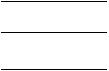
1. |
Mechanical Fuel Pump |
9. |
Lube Oil Dipstick/Fill Cap |
2. |
Injector Pump |
10. |
Starter |
3. |
Engine Speed Sensor |
11. |
Air Cleaner |
4. |
Poly V--Belt |
12. |
Generator Shockmount |
5. |
Radiator |
13. |
Receptacle Box |
6. |
Controls (See Figure 1-6 or Figure 1-8) |
14. |
Receptacle |
7. |
Engine Oil Filter |
15. |
Circuit Breaker |
8. |
Engine Shockmount (Typical) |
16. |
Air Filter Indicator (if equipped) |
Figure 1-1 Generator Set
1--3 |
T-343 |

|
1 |
|
2 |
|
3 |
11 |
|
10 |
4 |
|
5 |
9 |
6 |
|
|
|
7 |
|
8 |
1. |
Fuel Tank |
7. |
Engine |
2. |
Exhaust Muffler |
8. |
Coolant Overflow Bottle |
3. |
Solid State Battery Charger |
9. |
Alternating Current Generator |
4. |
Low Coolant Sensor (If Equipped) |
10. |
AC Generator Connection Box Access |
5. |
Water Temperature Sensor |
11. |
Battery |
6. |
Water Temperature Switch |
|
|
Figure 1-2 Generator Set -- Top View (Top Frame Members Removed for Clarity)
T-343 |
1--4 |
1.3 ENGINE
The engine is a vertical, in--line four cylinder diesel engine, which is direct--connected to the alternating current generator. Information on the major engine systems is provided in the following subparagraphs.
1.3.1 Electronic Governor Module
The electronic governor module is a solid state control module preprogrammed for 1800 RPM. The electronic governor module, along with the engine speed sensor, replaced the manual governor in order to provide a constant engine speed.
1.3.2 Engine Air System
The air cleaner (Item 11, Figure 1-1) is designed to prolong engine life and performance by preventing dirt and grit from entering the engine and causing excessive wear on all operating parts. In order for the air filter to operate properly, the operator must regularly maintain the air cleaner equipment in accordance with the instructions provided within this document.
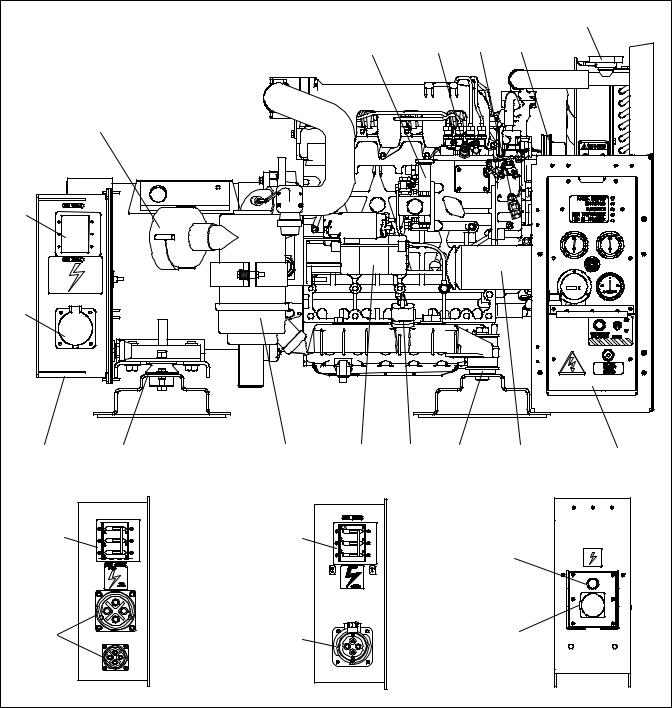
1.3.3 Lube Oil Filter Arrangement
The engine lubricating oil filter is mounted in a horizontal arrangement and shown in Figure 1-4.
1.3.4 Fuel System
The fuel system is fitted with an in--line pre--filter and a fuel filter, which also acts as a water separator. The filter is also fitted with a heater. The fuel system is shown in Figure 1-3.
1.4 ENGINE SCREW THREADS
All threads used on the engine are metric.
|
8 |
9 |
|
|
6 |
|
5 |
4 |
7 |
|
|
2 |
|
3 |
|
1 |
|
1. |
Fuel Tank |
5. |
Fuel Filter and Water |
2. |
Fuel Supply Line |
|
Separator |
3. |
Inline Fuel Filter |
6. |
Injection Pump |
4. |
Mechanical |
8. |
Fuel Bleed Valve |
|
Fuel Pump (Engine) |
7. |
Injector Nozzles |
|
|
9. |
Fuel Return Line |
Figure 1-3 Fuel System Diagram
1 |
2 |
|
|
|
3 |
4 |
|
1.Oil Filter (Primary)
2.Oil Pressure Sender
3.Oil Pressure Switch
4.Oil Pan
Figure 1-4 Lube Oil
1.5 ALTERNATING CURRENT GENERATOR 1.5.1 Principle of Operation
The Marathon Alternator Company (Lima) brushless AC generator (see Figure 1-2, item 9) is a self--regulated, rotating field synchronous unit. The generator stator and exciter stator are combined in a common housing. The generator field, exciter rotor, and rotating rectifier assembly are mounted on a common shaft. The output of the exciter rotor is applied to the generator field winding through a rotating, full--wave bridge, silicon rectifier unit.
All connections between the exciter stator windings and the generator stator windings are internal within the stator housing. Only the output power leads are connected at the terminal box, which is located on top of the generator.
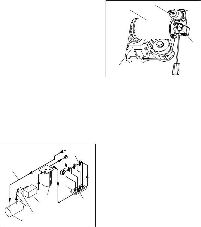
1.5.2 Alternating Current Generator Diagram
Figure 1-5 shows the internal schematic diagram of the generator, exciter, and rectifier unit. The generator is a three--phase unit, and the exciter stator and exciter rotor also have three--phase windings. A portion of the exciter stator windings is connected across a tap on the generator stator winding. This exciter shunt winding provides the generator field excitation power required for the generator no--load voltage. Another portion of the exciter stator windings is connected in series with the output of the generator and provides a compounding excitation characteristic.
1--5 |
T-343 |
The rotor is, in effect, the secondary of a rotating current transformer induction frequency converter. The exciter rotor output voltage is applied to the generator field windings by a three--phase, full wave rotating silicon rectifier unit. The response time of the excitation system is very fast as the exciter stator carries an alternating current corresponding to the load current that appears immediately on the exciter primary. An increase in load current will cause an immediate increase in the exciter secondary output voltage, which is rectified and applied to the generator field windings. The inherent compounding characteristics of the excitation system provide excellent voltage regulation even under heavy overload conditions.
FIELD |
|
|
|
SHUNT |
|
|
SERIES |
|
STATOR |
|
|
GENERATOR |
STATOR |
|
|
||
|
L |
|
|
O |
|
|
A |
|
|
D |
|
|
ROTOR |
|
RECTIFIER |
EXCITER |
|
ASSEMBLY |
||
|
||
Figure 1-5 A--C Generator Circuit Diagram |
||
 CAUTION
Observe proper polarity when installing the battery or connecting a battery charger. The negative battery terminal must be grounded. Reverse polarity may damage the charging system. When charging the battery in unit, isolate the battery by disconnecting the negative battery terminal first, then the positive. Once the battery has been charged, connect the positive battery terminal first, then the negative.
1.6 BATTERY CHARGER
The solid state battery charger (see Figure 1-2) is located to the left of the radiator. The charger is powered by the generator, and this input is protected by a circuit breaker located on the control panel. The battery charger produces a tapered charge (25 amps maximum) and is designed not to overcharge the battery.
1.7OPERATING CONTROLS AND INSTRUMENTS
1.7.1 Introduction
Components required for monitoring and controlling the unit are located in the control box, on the control panel (see Figure 1-6) and on the receptacle box (see Figure 1-1).
1.7.2 Control Panel and Related Components a. Gauges and Senders
1.Oil Pressure Gauge (see Figure 1-6, Figure 1-7, Figure 1-8)
The purpose of this gauge is to observe normal operating engine oil pressure. Normal oil pressure is 35 to 60 psig (3.3 to 5.2 kg/cm2).
2. Oil Pressure Sender (see Figure 1-4)
This device senses engine lube oil pressure and transmits a signal to the oil pressure gauge. The oil pressure sender is located on the oil filter housing.
3. Water Temperature Gauge (see Figure 1-6, Figure 1-7, Figure 1-8)
The function of this gauge is to observe water operating temperature. The gauge is connected to the water temperature sender.
4. Water Temperature Sender (see Figure 1-2)
This device senses engine water temperature and transmits a signal to the water temperature gauge.
5. Low Coolant Sensor (see Figure 1-2)
This device senses the coolant level inside the radiator and will complete a conductive circuit as long as the probes remain immersed in coolant. When the coolant level falls below the probes, a signal will be sent to the auto restart module, shutting down the engine and all 12--volt circuitry.
6. Auto Restart Module
Auto start/restart is provided to simplify the start--up process and provide an automatic restart feature that will automatically attempt to restart the unit in the event of shutdown. Four LEDs are used to indicate shutdown from overcrank, overspeed, low oil pressure, and high water temperature. A fifth LED is used to indicate the unit is running. Refer to Table 1-2 for system preset values.
The auto restart function will perform a series of six attempts to restart the unit and make three attempts within each series. Once the function has completed all 18 attempts, the unit will automatically lock out future crank attempts. Refer to Table 1-3 for detailed information on auto restart sequencing.
T-343 |
1--6 |
b. Meters
1. Ammeter (A)
The ammeter (see Figure 1-6, Figure 1-7, Figure 1-8) is an indicator of the charging system and unit electrical draw. It indicates the rate of discharge or charge of the battery. During start up, the intake heater draws approximately 42 amps.
2. Total Time Meter (TT)
The total time meter (see Figure 1-6, Figure 1-7, Figure 1-8) calculates the total hours and provides an accurate readout of accumulated engine running time. This data can be used to establish the proper periodic maintenance schedule (refer to Section 4.1).
c. Manual Switches
1. Intake Heater Switch (HS) (see Figure 1-6, Figure 1-7)
The intake heater switch is of the momentary type. When held in the PREHEAT position, the switch allows approximately 42 amps of battery current to flow into the intake heater, which preheats the air within the intake manifold and allows the engine to start. After starting the engine, the intake heater switch should continue to be held in the ON position for approximately 5 seconds until the engine has developed enough oil pressure to close the oil pressure safety switch.
2. Ignition Switch (IGN) (see Figure 1-6, Figure 1-7)
The ignition switch is of the momentary type to be used in the OFF/ON/START positions. When held in the START (ignition) position, it energizes the starter motor solenoid, which in turn allows the starter motor to crank the engine. The switch is released to the RUN position once the engine has started.
3. Ignition Switch (IGN)(Auto Restart) (see Figure 1-8)
The ignition switch is of the maintained contact type to be used in the RUN/OFF positions. When switched to the RUN position, it energizes the control module, which in turn controls all functions of the genset.
1.8 SAFETY DEVICES
Safety devices, such as circuit breakers, fuses, and safety switches, protect system components from damage.
The AC generator, solid state battery charger, fuel heater, high water temperature, safety relay, total time meter and intake air heater are protected by circuit breakers. If a safety device opens and there is an interruption of electrical current, the electronic governor module will be de--energized, which will also de--energize the fuel solenoid, interrupt the fuel flow to the engine and stop the engine.
In units with auto restart, the engine, engine control devices, and engine monitoring devices are protected by the auto restart module, low coolant sensor (if equipped), circuit breaker, low oil pressure switch, and high water temperature switch. These safety devices monitor system operating conditions and open a set of electrical contacts when an unsafe condition occurs. If a safety device opens and there is an interruption of electrical current, the electronic governor module will be de--energized, which will also de--energize the fuel solenoid, interrupt the fuel flow to the engine and stop the engine.
De--energizing the fuel solenoid shuts off the fuel supply to the engine; thus stopping the engine. Safety device specifications are provided in Table 1-4.
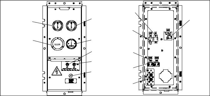
CONTROL |
|
PANEL |
|
2 |
3 |
|
|
1 |
4 |
|
5 |
|
6 |
|
7 |
CONTROL |
|
BOX |
12 |
|
|
|
13 |
|
11 |
|
10 |
|
9 |
|
8 |
1. |
Total Time Meter |
8. |
Ground Studs |
2. |
Water Temperature Gauge |
9. |
Circuit Breaker (CB2) |
3. |
Oil Pressure Gauge |
10. |
Circuit Breaker (CB3) |
4. |
Ammeter |
11. |
Intake Heater Relay |
5. |
Intake Air Heater Switch |
12. |
Safety Relay |
6. |
Ignition Switch |
13. |
Intake Heater Timer |
7. |
Battery Charger Circuit Breaker (CB5) |
|
|
Figure 1-6 Standard Control Panel and Box
1--7 |
T-343 |
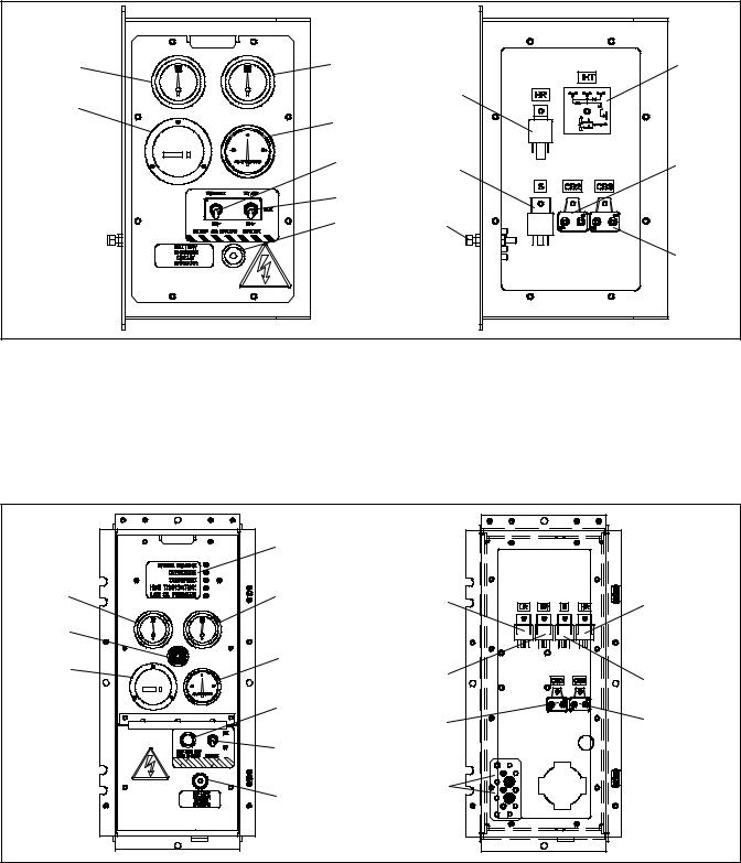
CONTROL |
|
CONTROL |
|
PANEL |
|
BOX |
|
2 |
3 |
|
11 |
1 |
|
10 |
|
4 |
|
|
|
|
|
|
|
|
5 |
9 |
12 |
|
|
|
|
|
6 |
|
|
|
7 |
8 |
|
|
|
|
13 |
1. |
Total Time Meter |
8. |
Ground Studs |
2. |
Water Temperature Gauge |
9. |
Safety Relay |
3. |
Oil Pressure Gauge |
10. |
Intake Heater Relay |
4. |
Ammeter |
11. |
Intake Heater Timer |
5. |
Intake Air Heater Switch |
12. |
Circuit Breaker (CB2) |
6. |
Ignition Switch |
13. |
Circuit Breaker (CB3) |
7.Battery Charger Fuse or Circuit Breaker (CB5)
Figure 1-7 Customer Specific Control Panel and Box
CONTROL |
|
PANEL |
4 |
|
|
3 |
5 |
2 |
|
1 |
6 |
|
|
|
7 |
|
8 |
|
9 |
CONTROL |
|
BOX |
|
13 |
14 |
12 |
15 |
|
|
11 |
16 |
10 |
|
1. |
Total Time Meter |
9. |
Battery Charger Fuse |
2. |
Engine Start Alarm (Buzzer) |
|
or Circuit Breaker (CB5) |
3. |
Water Temperature Gauge |
10. |
Ground Studs |
4. |
Auto Restart Module |
11. |
Circuit Breaker (CB2) |
5. |
Oil Pressure Gauge |
12. |
Starter Relay (SR) |
6. |
Ammeter |
13. |
Low Coolant Relay (LR) |
7. |
Engine Start/Intake Heater |
14. |
Intake Heater Relay (HR) |
|
Energized Light |
15. |
Safety Relay (S) |
8. |
Ignition Switch |
16. |
Circuit Breaker (CB3) |
|
Figure 1-8 Auto Restart Control Box and Panel |
||
T-343 |
1--8 |
|
|
 Loading...