


50ZH024-060 Packaged Heat Pump Units
Visit www.carrier.com
Installation, Start-Up and Service Instructions
NOTE: Read the entire instruction manual before starting the installation.
TABLE OF CONTENTS |
|
SAFETY CONSIDERATIONS ..................................................... |
1 |
INTRODUCTION .......................................................................... |
2 |
RECEIVING AND INSTALLATION .......................................... |
2 |
Check Equipment...................................................................... |
2 |
IDENTIFY UNIT ................................................................ |
2 |
INSPECT SHIPMENT ........................................................ |
2 |
Provide Unit Support ................................................................ |
2 |
SLAB MOUNT ................................................................... |
2 |
GROUND MOUNT ............................................................ |
2 |
Provide Clearances.................................................................... |
2 |
Place Unit.................................................................................. |
2 |
Select and Install Ductwork ..................................................... |
2 |
INSTALL FLANGES FOR DUCTWORK CONNEC- |
|
TIONS (50ZH060 ONLY) .................................................. |
6 |
CONVERTING HORIZONTAL DISCHARGE UNITS TO |
|
DOWNFLOW (VERTICAL) DISCHARGE...................... |
6 |
Provide for Condensate Disposal ............................................. |
6 |
Install Electrical Connections ................................................... |
7 |
HIGH-VOLTAGE CONNECTIONS.................................. |
7 |
ROUTING POWER LEADS INTO UNIT ........................ |
8 |
CONNECTING GROUND LEAD TO UNIT |
|
GROUND ............................................................................ |
8 |
ROUTING CONTROL POWER WIRES .......................... |
8 |
ACCESSORY ELECTRIC HEAT WIRING ..................... |
8 |
SPECIAL PROCEDURES FOR 208-V OPERATION ..... |
8 |
PRE-START-UP ............................................................................ |
9 |
START-UP ..................................................................................... |
9 |
Check for Refrigerant Leaks .................................................. |
10 |
LOCATE AND REPAIR REFRIGERANT LEAKS AND |
|
CHARGE THE UNIT AS FOLLOWS: ........................... |
10 |
Start-Up Cooling Section and Make Adjustments ................ |
10 |
CHECKING COOLING CONTROL OPERATION ....... |
10 |
COMPRESSOR ROTATION ........................................... |
10 |
Refrigerant Charge.................................................................. |
10 |
NO CHARGE .................................................................... |
10 |
LOW CHARGE COOLING ............................................. |
10 |
TO USE THE COOLING CHARGING CHART............ |
10 |
HEATING MODE CHARGE ........................................... |
11 |
Indoor Airflow and Airflow Adjustments.............................. |
11 |
FOR 208/230-V ................................................................. |
12 |
FOR 460-V MOTORS ...................................................... |
12 |
Unit Controls........................................................................... |
12 |
HIGH-PRESSURE RELIEF VALVE............................... |
12 |
LOSS OF CHARGE SWITCH ......................................... |
12 |
COMPRESSOR OVERLOAD.......................................... |
12 |
Sequence of Operation............................................................ |
12 |
FAN OPERATION............................................................ |
12 |
COOLING.......................................................................... |
14 |
HEAT PUMP HEATING.................................................. |
14 |
DEFROST.......................................................................... |
15 |
ELECTRIC RESISTANCE HEATING............................ |
15 |
MAINTENANCE......................................................................... |
15 |
Air Filter.................................................................................. |
16 |
Unit Top Removal (Outdoor-Coil Side) ................................ |
16 |
Indoor Blower and Motor....................................................... |
16 |
Outdoor Coil, Indoor Coil, and Condensate Drain Pan ........ |
16 |
Outdoor Fan ............................................................................ |
17 |
Electrical Controls and Wiring............................................... |
18 |
Refrigerant Circuit .................................................................. |
18 |
Indoor Airflow ........................................................................ |
18 |
Metering Devices .................................................................... |
18 |
Lubrication .............................................................................. |
18 |
Liquid Line Strainer................................................................ |
18 |
High Flow Valves................................................................... |
19 |
TROUBLESHOOTING ............................................................... |
22 |
START-UP CHECKLIST............................................................ |
23 |
NOTE TO INSTALLERÐBefore installation, READ THESE INSTRUCTIONS CAREFULLY AND COMPLETELY. Also, make sure the User's Manual and Replacement Guide are left with the unit after installation.
C00155
Fig. 1ÐUnit 50ZH
SAFETY CONSIDERATIONS
Installation and servicing of air-conditioning equipment can be hazardous due to system pressure and electrical components. Only trained and qualified workers should install, repair, or service air-conditioning equipment.
Untrained workers can perform basic maintenance functions of cleaning coils and filters. All other operations should be performed by trained service people. When working on air-conditioning
Manufacturer reserves the right to discontinue, or change at any time, specifications or designs without notice and without incurring obligations.
Book |
1 |
4 |
PC 101 |
Catalog No. 535-00080 |
Printed in U.S.A. |
Form 50ZH-5SI |
Pg 1 |
7-03 |
Replaces: 50ZH-4SI |
Tab |
6 |
8 |
|
|
|
|
|
|
|
equipment, pay attention to precautions in the literature, tags, and labels attached to the unit, and other safety precautions that may apply.
Follow all safety codes. Wear safety glasses and work gloves. Use quenching cloth for unbrazing operations. Have fire extinguisher available for all brazing operations.
Before performing service or maintenance operations on system, turn off main power to unit and install lockout tag. Turn off accessory heater power switch if applicable. Electrical shock can cause serious injury or death.
Recognize safety information. This is the safety-alert symbol  . When you see this symbol in instructions or manuals, be alert to the potential for personal injury.
Understand the signal words DANGER, WARNING, CAUTION, and NOTE. These words are used with the safety-alert symbol. DANGER identifies the most serious hazards which will result in severe personal injury or death. WARNING signifies a hazard which could result in personal injury or death. CAUTION is used to identify unsafe practices which would result in minor personal injury or product and property damage. NOTE is used to highlight suggestions which will result in enhanced installation, reliability, or operation.
These instructions cover minimum requirements and conform to existing national standards and safety codes. In some instances, these instructions exceed certain local codes and ordinances, especially those that may not have kept up with changing residential construction practices. We require these instructions as a minimum for a safe installation.
INTRODUCTION
50ZH heat pump units are fully self-contained and designed for outdoor installation (See Fig. 1). As shown in Fig. 2-4, units are shipped in a horizontal-discharge configuration for installation on a ground-level slab. All units can be field-converted to downflow discharge configurations for rooftop applications with a fieldsupplied plenum.
RECEIVING AND INSTALLATION
Step 1ÐCheck Equipment
IDENTIFY UNIT
The unit model number and serial number are stamped on the unit identification plate. Check this information against shipping papers. Verify that unit voltage and amperage listed on unit rating plate agree with power supplied for equipment.
INSPECT SHIPMENT
Inspect for shipping damage while unit is still on shipping pallet. If unit appears to be damaged or is torn loose from its securing points, have it examined by transportation inspectors before removal. Forward claim papers directly to transportation company. Manufacturer is not responsible for any damage incurred in transit.
Check all items against shipping list. Immediately notify the nearest Carrier Air Conditioning office if any item is missing.
To prevent loss or damage, leave all parts in original packages until installation.
Step 2ÐProvide Unit Support
SLAB MOUNT
Place the unit on a rigid, level surface, suitable to support the unit weight. A concrete pad or a suitable fiberglass mounting pad is recommended. The flat surface should extend approximately 2-in.
beyond the unit casing on the 2 sides. The duct connection side and condensate drain connection sides should be flush with the edge of the flat surface.
A 6-in. wide gravel apron should be used around the flat surface to prevent airflow blockage by grass or shrubs. Do not secure the unit to the flat surface except where required by local codes.
The unit should be level to within 1/4 inch. This is necessary for the unit drain to function properly.
GROUND MOUNT
The unit may also be installed directly on the ground if local codes permit. Place unit on level ground prepared with gravel for condensate discharge.
Step 3ÐProvide Clearances
The required minimum service clearances and clearances to combustibles are shown in Fig. 2-4. Adequate ventilation and outdoor coil air must be provided.
The outdoor fan pulls air through the outdoor coil and discharges it through the fan on the top cover. Be sure that the fan discharge does not recirculate to the outdoor coil. Do not locate the unit in either a corner or under an overhead obstruction. The minimum clearance under a partial overhang (such as a normal house overhang) is 48 in. above the unit top. The maximum horizontal extension of a partial overhang must not exceed 48 inches.
Do not place the unit where water, ice, or snow from an overhang or roof will damage or flood the unit. The unit may be installed on wood flooring or on Class A, B, or C roof covering materials.
Do not restrict outdoor coil airflow. An air restriction at either the outdoor-air inlet or the fan discharge can be harmful to compressor life.
Step 4ÐPlace Unit
Unit can be moved with the rigging holds provided in the unit base. Refer to Table 1 for operating weights. Use extreme caution to prevent damage when moving the unit. Unit must remain in an upright position during all moving operations. The unit must be level with in 1/4º for proper condensate drainage; the ground-level pad must be level before setting the unit in place. When a field-fabricated support is used, be sure that the support is level and that it properly supports the unit.
Step 5ÐSelect and Install Ductwork
The design and installation of the duct system must be in accordance with:
·the standards of the NFPA (National Fire Protection Association) for installation of nonresidence-type air conditioning and ventilating systems
·NFPA90A or residence-type, NFPA90B; and/or local codes and residence-type, NFPA 90B
·and/or local codes and ordinances
Select and size ductwork, supply-air registers and return-air grilles according to ASHRAE (American Society of Heating, Refrigeration, and Air Conditioning Engineers) recommendations.
Use the duct flanges provided on the supplyand return-air openings on the side of the unit. See Fig. 2-4 for connection sizes and locations. The 14-in. round duct collars (size 024-048 units) are shipped inside the unit attached to the indoor blower. They are field-installed and must be removed from the indoor cavity prior to start-up, even if they are not used for installation.
2

REQUIRED CLEARANCE TO COMBUSTIBLE MATL. |
|
|
INCHES [mm] |
TOP OF UNIT......................................................................................... |
0 |
DUCT SIDE OF UNIT............................................................................. |
0 |
SIDE OPPOSITE DUCTS ...................................................................... |
0 |
BOTTOM OF UNIT ................................................................................. |
0 |
NEC. REQUIRED CLEARANCES. |
|
|
INCHES [mm] |
BETWEEN UNITS, POWER ENTRY SIDE .................................... |
42.00 [1066.8] |
UNIT AND UNGROUNDED SURFACES, POWER ENTRY SIDE .36.00 [914.0] |
|
UNIT AND BLOCK OR CONCRETE WALLS AND OTHER |
|
GROUNDED SURFACES, POWER ENTRY SIDE......................... |
42.00 [1066.8] |
REQUIRED CLEARANCE FOR OPERATION AND SERVICING |
|
|
INCHES [mm] |
CONDENSER. COIL ACCESS SIDE.............................................. |
30.00 [762.0] |
POWER ENTRY SIDE.................................................................... |
30.00 [762.0] |
(EXCEPT FOR NEC REQUIREMENTS) |
|
UNIT TOP ....................................................................................... |
48.00 [1219.2] |
SIDE OPPOSITE DUCTS .............................................................. |
30.00 [762.0] |
LEGEND |
|
NEC – National Electrical Code |
|
NOTES:
1. Clearances must be maintained to prevent recirculation of air from outdoorfan discharge, with the exception of the condenser coil (36.00 in [914.0 mm]. A removable fence or barricade requires no clearance.
2. Dimensions are in inches. Dimensions in [ ] are in millimeters.
|
|
|
|
|
|
|
|
|
|
|
|
|
|
|
|
|
|
|
|
|
|
|
|
|
|
|
|
|
|
|
|
|
|
|
|
|
|
|
|
|
|
C00156 |
|
|
|
|
|
|
|
|
|
|
|
|
|
|
|
|
|
|
|
|
|
|
|
|
|
|
|
|
|
|
|
|
|
|
|
|
|
|
|
|
|
|
|
|
|
|
|
|
|
|
|
|
|
|
|
|
|
|
|
|
|
|
|
|
|
|
|
|
|
|
|
|
|
|
|
|
|
|
|
|
|
|
|
|
|
|
|
|
|
|
|
|
|
|
|
|
|
|
|
|
|
|
|
|
|
|
|
|
|
|
|
|
|
|
|
|
|
|
|
|
|
|
|
|
|
|
|
|
|
|
|
|
|
|
|
|
|
|
|
|
|
|
|
|
|
|
|
|
|
|
|
|
|
|
|
|
|
|
|
|
|
|
|
|
|
|
|
|
|
|
|
|
UNIT |
|
|
ELECTRICAL CHARACTERISTICS |
|
|
|
|
UNIT WEIGHT |
CENTER OF GRAVITY IN. (MM) |
|||||||||||||||||||||||||||||||||
|
|
|
|
|
|
lb |
kg |
X |
|
|
|
|
|
|
|
|
|
|
|
Y |
|
|
Z |
|||||||||||||||||||
|
|
|
|
|
|
|
|
|
|
|
|
|
|
|
|
|
|
|
|
|
|
|
|
|
|
|
|
|
|
|
||||||||||||
|
|
|
|
|
|
|
|
|
|
|
|
|
|
|
|
|
|
|
|
|
|
|
|
|
|
|
|
|
|
|
|
|
|
|
|
|
|
|
|
|
|
|
50ZH024 |
208/230-1-60 |
|
232 |
|
|
106 |
14.0 (356) |
19.0 (483) |
|
12.0 (305) |
||||||||||||||||||||||||||||||||
50ZH030 |
208/230-1-60, |
|
254 |
|
|
116 |
14.0 (356) |
19.0 (483) |
|
12.0 (305) |
||||||||||||||||||||||||||||||||
208/230±3±60 |
|
|
|
|
||||||||||||||||||||||||||||||||||||||
|
|
|
|
|
|
|
|
|
|
|
|
|
|
|
|
|
|
|
|
|
|
|
|
|
|
|
|
|
|
|
|
|
|
|
|
|
||||||
|
|
|
|
|
|
|
|
|
|
|
|
|
|
|
|
|
|
|
|
|
|
|
|
|
|
|
|
|
|
|
|
|
|
|
|
|
|
|
|
|
|
|
Fig. 2ÐUnit Base Dimensions, 50ZH024-030
3
REQUIRED CLEARANCE TO COMBUSTIBLE MATL.
|
INCHES [mm] |
TOP OF UNIT......................................................................................... |
0 |
DUCT SIDE OF UNIT............................................................................. |
0 |
SIDE OPPOSITE DUCTS ...................................................................... |
0 |
BOTTOM OF UNIT ................................................................................. |
0 |
NEC. REQUIRED CLEARANCES.
|
INCHES |
[mm] |
BETWEEN UNITS, POWER ENTRY SIDE .................................... |
42.00 |
[1066.8] |
UNIT AND UNGROUNDED SURFACES, POWER ENTRY SIDE .36.00 [914.0] |
||
UNIT AND BLOCK OR CONCRETE WALLS AND OTHER |
|
|
GROUNDED SURFACES, POWER ENTRY SIDE......................... |
42.00 |
[1066.8] |
REQUIRED CLEARANCE FOR OPERATION AND SERVICING |
|
|
|
INCHES [mm] |
|
CONDENSER. COIL ACCESS SIDE.............................................. |
|
30.00 [762.0] |
POWER ENTRY SIDE.................................................................... |
30.00 |
[762.0] |
(EXCEPT FOR NEC REQUIREMENTS) |
|
|
UNIT TOP ....................................................................................... |
48.00 |
[1219.2] |
SIDE OPPOSITE DUCTS .............................................................. |
30.00 |
[762.0] |
LEGEND
NEC – National Electrical Code
NOTES:
1. Clearances must be maintained to prevent recirculation of air from outdoorfan discharge, with the exception of the condenser coil (36.00 in [914.0 mm]. A removable fence or barricade requires no clearance.
2. Dimensions are in inches. Dimensions in [ ] are in millimeters.
|
|
|
|
|
|
|
|
|
|
|
|
|
|
|
|
|
|
|
|
|
|
|
|
|
|
|
|
|
|
|
|
|
|
|
|
|
|
|
|
|
|
|
|
|
|
|
|
C00003 |
|
|
|
|
|
|
|
|
|
|
|
|
|
|
|
|
|
|
|
|
|
|
|
|
|
|
|
|
|
|
|
|
|
|
|
|
|
|
|
|
|
|
|
|
|
|
|
|
|
|
|
|
|
|
|
|
|
|
|
|
|
|
|
|
|
|
|
|
|
|
|
|
|
|
|
|
|
|
|
|
|
|
|
|
|
|
|
|
|
|
|
|
|
|
|
|
|
|
|
|
|
|
|
|
|
|
|
|
|
|
|
|
|
|
|
|
|
|
|
|
|
|
|
|
|
|
|
|
|
|
|
|
|
|
|
|
|
|
|
|
|
|
|
|
|
|
|
UNIT |
|
|
ELECTRICAL CHARACTERISTICS |
|
|
|
|
UNIT WEIGHT |
CENTER OF GRAVITY IN. (MM) |
|||||||||||||||||||||||||||||||||||||||
|
|
|
|
|
|
lb |
kg |
X |
|
|
|
|
|
|
|
|
|
Y |
Z |
|||||||||||||||||||||||||||||
|
|
|
|
|
|
|
|
|
|
|
|
|
|
|
|
|
|
|
|
|
|
|
|
|
|
|
|
|
|
|
|
|
|
|||||||||||||||
|
|
|
|
|
|
|
|
|
|
|
|
|
|
|
|
|
|
|
|
|
|
|
|
|
|
|
|
|
|
|
|
|
|
|
|
|
|
|
|
|
|
|
|
|
|
|
|
|
50ZH036 |
208/230-1-60, 208/230-3-60, |
|
|
|
|
|
|
|
|
|
277 |
126 |
14.0 (356) |
|
|
|
|
19.0 (483) |
|
15.0 (381) |
||||||||||||||||||||||||||||
460±3±60 |
|
|
|
|
|
|
|
|
|
|
|
|
|
|
||||||||||||||||||||||||||||||||||
|
|
|
|
|
|
|
|
|
|
|
|
|
|
|
|
|
|
|
|
|
|
|
|
|
|
|
|
|
|
|
|
|
|
|
|
|
|
|
|
|
|
|
||||||
50ZH042 |
208/230-1-60, 208/230-3-60, |
|
|
|
|
|
|
|
|
|
295 |
134 |
14.0 (356) |
|
|
|
|
19.0 (483) |
|
15.0 (381) |
||||||||||||||||||||||||||||
460±3±60 |
|
|
|
|
|
|
|
|
|
|
|
|
|
|
||||||||||||||||||||||||||||||||||
|
|
|
|
|
|
|
|
|
|
|
|
|
|
|
|
|
|
|
|
|
|
|
|
|
|
|
|
|
|
|
|
|
|
|
|
|
|
|
|
|
|
|
||||||
50ZH048 |
208/230-1-60, 208/230-3-60, |
|
|
|
|
|
|
|
|
|
328 |
149 |
14.0 (356) |
|
|
|
|
19.0 (483) |
|
15.0 (381) |
||||||||||||||||||||||||||||
460±3±60 |
|
|
|
|
|
|
|
|
|
|
|
|
|
|
||||||||||||||||||||||||||||||||||
|
|
|
|
|
|
|
|
|
|
|
|
|
|
|
|
|
|
|
|
|
|
|
|
|
|
|
|
|
|
|
|
|
|
|
|
|
|
|
|
|
|
|
||||||
|
|
|
|
|
|
|
|
|
|
|
|
|
|
|
|
|
|
|
|
|
|
|
|
|
|
|
|
|
|
|
|
|
|
|
|
|
|
|
|
|
|
|
|
|
|
|
|
|
Fig. 3ÐUnit Base Dimensions, 50ZH036±048
4

REQUIRED CLEARANCE TO COMBUSTIBLE MATL.
|
INCHES [mm] |
TOP OF UNIT......................................................................................... |
0 |
DUCT SIDE OF UNIT............................................................................. |
0 |
SIDE OPPOSITE DUCTS ...................................................................... |
0 |
BOTTOM OF UNIT ................................................................................. |
0 |
NEC. REQUIRED CLEARANCES.
|
INCHES |
[mm] |
BETWEEN UNITS, POWER ENTRY SIDE .................................... |
42.00 |
[1066.8] |
UNIT AND UNGROUNDED SURFACES, POWER ENTRY SIDE .36.00 [914.0] |
||
UNIT AND BLOCK OR CONCRETE WALLS AND OTHER |
|
|
GROUNDED SURFACES, POWER ENTRY SIDE......................... |
42.00 |
[1066.8] |
REQUIRED CLEARANCE FOR OPERATION AND SERVICING |
|
|
|
INCHES [mm] |
|
CONDENSER. COIL ACCESS SIDE.............................................. |
30.00 [762.0] |
|
POWER ENTRY SIDE.................................................................... |
30.00 |
[762.0] |
(EXCEPT FOR NEC REQUIREMENTS) |
|
|
UNIT TOP ....................................................................................... |
48.00 |
[1219.2] |
SIDE OPPOSITE DUCTS .............................................................. |
30.00 |
[762.0] |
LEGEND
NEC – National Electrical Code
NOTES:
1. Clearances must be maintained to prevent recirculation of air from outdoorfan discharge, with the exception of the condenser coil (36.00 in [914.0 mm]. A removable fence or barricade requires no clearance.
2. Dimensions are in inches. Dimensions in [ ] are in millimeters.
|
|
|
|
|
|
|
|
|
|
|
|
|
|
C00158 |
|
|
|
|
|
|
|
|
|
|
|
|
|
|
|
|
|
|
|
|
|
|
|
|
|
|
|
|
|
|
UNIT |
ELECTRICAL CHARACTERISTICS |
UNIT WEIGHT |
CENTER OF GRAVITY IN. (MM) |
|||||||||||
lb |
kg |
X |
|
|
|
|
|
|
Y |
Z |
||||
|
|
|
|
|
|
|
|
|||||||
50ZH060 |
208/230-1-60, 208/230-3-60, 460-3-60 |
368 |
167 |
14.0 (356) |
20.0 (508) |
|
16.0 (406) |
|||||||
Fig. 4ÐUnit Base Dimensions, 50ZH060
5
INSTALL FLANGES FOR DUCTWORK CONNECTIONS (50ZH060 ONLY)
The 50ZH060 units are shipped with flanges which must be field-installed on the unit.
To install unit flanges:
1.Five pieces of flange are shipped on the return-air opening of the unit. Remove the flanges from the shipping position (See Fig. 5). Screws are field-supplied.
2.One piece of flange is used as it is shipped (straight). Bend the other 4 pieces at right angles.
3.Install the straight flange on the right side of the return-air opening in holes provided. (See Fig. 6). Flanges should stick out from unit to allow for connection of ductwork.
4.Install 2 hand-formed flanges onto return air opening in holes provided to form a rectangle around the return air opening.
5.Install remaining 2 hand-formed flanges around discharge air opening in holes provided.
6.Ductwork can now be attached to flanges.
When designing and installing ductwork, consider the following:
When connecting ductwork to units, do not drill deeper than 3/4 inch in shaded area shown in Fig. 7 or coil may be damaged.
·All units should have field-supplied filters installed in the return-air side of the unit. Recommended sizes for filters are shown in Table 1.
·Avoid abrupt duct size increases and reductions. Abrupt change in duct size adversely affects air performance.
IMPORTANT: Use flexible connectors between ductwork and unit to prevent transmission of vibration. Use suitable gaskets to ensure weathertight and airtight seal. When electric heat is installed, use fire proof canvas (or similar heat resistant material) connector between ductwork and unit discharge connection. If flexible duct is used, insert a sheet metal sleeve inside duct. Heat resistant duct connector (or sheet metal sleeve) must ectend 24±in. from the unit discharge connection flange into the ductwork.
·Size ductwork for cooling air quantity (cfm). The minimum air quantity for proper electric heater operation is listed in Table 2. Heater limit switches may trip at air quantities below those recommended.
·Insulate and weatherproof all external ductwork. Insulate and cover with a vapor barrier all ductwork passing through conditioned spaces. Follow latest Sheet Metal and Air Conditioning Contractors National Association (SMACNA) and Air Conditioning Contractors Association (ACCA) minimum installation standards for residential heating and air conditioning systems.
·Secure all ducts to building structure. Flash, weatherproof, and vibration-isolate duct openings in wall or roof according to good construction practices.
Figure 8 shows a typical duct system with 50ZH unit installed.
FIVE PIECES OF DUCT
FLANGE ATTACHED
HERE FOR SHIPMENT
C00005
Fig. 5ÐShipping Location of Duct Flanges (Size 060 Only)
HAND
FORM
HAND FORM
STRAIGHT PIECE
C00006
Fig. 6ÐFlanges Installed on 50ZH060 Units
CONVERTING HORIZONTAL DISCHARGE UNITS TO DOWNFLOW (VERTICAL) DISCHARGE
Before performing service or maintenance operations on system, turn off main power to unit and install lockout tag. Turn off accessory heater power switch if applicable. Electrical shock can cause serious injury or death.
Units are dedicated side supply products. They are not convertible to vertical air supply. A field-supplied plenum must be used to convert to vertical air discharge.
Step 6ÐProvide for Condensate Disposal
NOTE: Be sure that condensate-water disposal methods comply with local codes, restrictions, and practices.
6
Unit removes condensate through a 1 3/64-in. ID hole (using 3/4-in. OD piping or tubing) which is located at the end of the unit. See Fig. 2-4 for location of condensate connection.
19.17″ |
3.92″ |
|
|||||
|
|
|
|
|
|
|
|
|
|
|
|
|
|
|
|
|
|
|
|
|
|
|
|
|
|
|
|
|
|
|
|
|
|
|
|
|
|
|
|
|
|
|
|
|
|
|
|
C00007
Fig. 7ÐArea Not to Be Drilled More Than 3/4-in.
Condensate water can be drained directly onto the roof in rooftop installations (where permitted) or onto a gravel apron in groundlevel installations. Install a field-supplied condensate trap at end of condensate connection to ensure proper drainage. Make sure that the outlet of the trap is at least 1 in. lower than the drain-pan condensate connection to prevent the pan from overflowing. Prime the trap with water. When using a gravel apron, make sure it slopes away from the unit.
If the installation requires draining the condensate water away from the unit, install a 2-in. trap using a 3/4-in. OD tubing or pipe. (See Fig. 9 and 10.) Make sure that the outlet of the trap is at least 1 in. lower than the unit drain-pan condensate connection to prevent the pan from overflowing. Prime the trap with water. Connect a drain tube using a minimum of 3/4-in. PVC, 3/4-in. CPVC, or 3/4-in. copper pipe (all field supplied). Do not undersize the tube. Pitch the drain tube downward at a slope of at least 1 in. for every 10 ft of horizontal run. Be sure to check the drain tube for leaks. Prime trap at the beginning of the cooling season start-up. Allowable glues for condensate trap connection are: Standard ABS, CPVC, or PVC cement.
Step 7ÐInstall Electrical Connections
The unit cabinet must have an uninterrupted, unbroken electrical ground to minimize the possibility of personal injury if an electrical fault should occur. This ground may consist of an electrical wire connected to the unit ground in the control compartment, or conduit approved for electrical ground when installed in accordance with NEC (National Electrical Code), ANSI (American National Standards Institute)/NFPA (latest edition) (in Canada, Canadian Electrical Code CSA C22.1) and local electrical codes. Failure to adhere to this warning could result in serious injury or death.
Failure to follow these precautions could result in damage to the unit being installed:
1.Make all electrical connections in accordance with NEC ANSI/NFPA (latest edition) and local electrical codes governing such wiring. In Canada, all electrical connections must be in accordance with CSA standard C22.1 Canadian Electrical Code Part 1 and applicable local codes. Refer to unit wiring diagram.
2.Use only copper conductor for connections between field-supplied electrical disconnect switch and unit. DO NOT USE ALUMINUM WIRE.
3.Be sure that high-voltage power to unit is within operating voltage range indicated on unit rating plate.
4.Insulate low-voltage wires for highest voltage contained within conduit when low-voltage control wires are run in same conduit as high-voltage wires.
5.Do not damage internal components when drilling through any panel to mount electrical hardware, conduit, etc. On 3-phase units, ensure phases are balanced within 2 percent. Consult local power company for correction of improper voltage and/or phase imbalance.
HIGH-VOLTAGE CONNECTIONS
INDOOR

 THERMOSTAT
RETURN
AIR
TOP COVER
Power Wiring
Control Wiring
Condenser Airflow
Evaporator Airflow
POWER AND
LOW-VOLTAGE
ENTRY
COMPOSITE
RUST-PROOF
BASEPAN
CONDENSATE
DRAIN
CONNECTION
*Separate disconnect per NEC (National Electrical Code) required for electric heater when singlepoint conection is not used.
FROM
POWER
SOURCE
DISCONNECT PER NEC* (UNIT AND ELECTRIC HEATER)
C00008
C00008
Table 2ÐMinimum Airflow for Safe Electric Heater Operation (CFM)
SIZE
024 |
030 |
036 |
042 |
048 |
060 |
600 |
750 |
900 |
1050 |
1200 |
1500 |
Fig. 8ÐTypical installation
1” (25mm) MIN.
TRAP
OUTLET
2” (50mm) MIN.
C99013
Fig. 9ÐCondensate Trap (Using Tubing)
The unit must have a separate electrical service with a fieldsupplied, waterproof disconnect switch mounted at, or within sight from the unit. Refer to the unit rating plate for maximum fuse/circuit breaker size and minimum circuit amps (ampacity) for wire sizing. See Table 3 for electrical data.
7
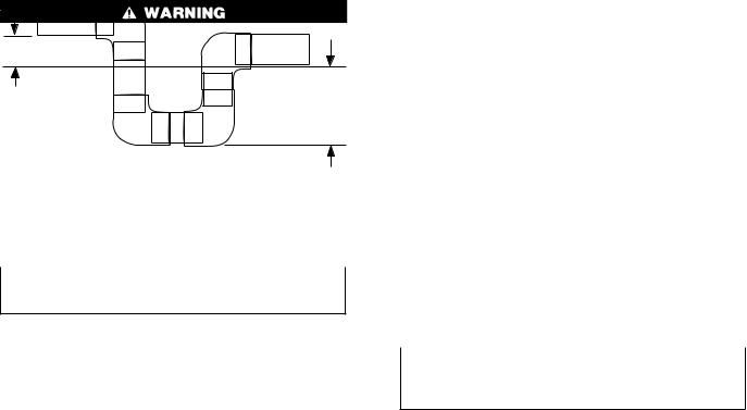
Table 1 Ð Physical Data
UNIT 50ZH |
024 |
030 |
|
036 |
|
042 |
048 |
060 |
OPERATING WEIGHT (lbs) |
232 |
254 |
|
277 |
|
295 |
328 |
368 |
COMPRESSOR TYPE |
|
|
|
|
Scroll |
|
|
|
REFRIGERANT Charge (lb) |
|
|
|
|
R-22 |
|
|
|
|
|
|
|
|
|
|
|
|
3.7 |
5.8 |
|
5.9 |
|
6.6 |
9.1 |
9.7 |
|
|
|
|
||||||
REFRIGERANT METERING DEVICE |
|
|
|
Acutrol™ System |
|
|
||
OUTDOOR COIL |
|
|
Copper Tubes, Aluminum Plate Fins |
|
||||
Rows...Fins/in. |
1...17 |
2...17 |
|
1...17 |
|
2...17 |
2...17 |
2...17 |
Face Area (sq ft) |
7.9 |
6.7 |
|
11.1 |
|
9.3 |
11.1 |
12.7 |
|
|
|
|
|
|
|
|
|
OUTDOOR-FAN MOTOR CFM |
|
|
|
|
Propeller |
|
|
|
|
|
|
|
|
|
|
|
|
1800 |
2000 |
|
2600 |
|
2600 |
2600 |
3200 |
|
Nominal Rpm |
|
|
||||||
825 |
1100 |
|
1100 |
|
1100 |
1100 |
1100 |
|
Motor Hp |
|
|
||||||
1/8 |
1/4 |
|
1/4 |
|
1/4 |
1/4 |
1/2 |
|
Diameter (in.) |
|
|
||||||
20 |
20 |
|
20 |
|
20 |
20 |
20 |
|
|
|
|
||||||
INDOOR COIL |
|
|
Copper Tubes, Aluminum Plate Fins |
|
||||
Rows...Fins/in. |
2...15 |
3...15 |
|
3...15 |
|
3...15 |
4...15 |
4...15 |
Face Area (sq ft) |
3.1 |
3.1 |
|
4.0 |
|
4.0 |
4.4 |
4.9 |
INDOOR FAN MOTOR |
|
|
|
Direct Drive |
|
|
||
Blower Motor Size (in.) |
10 x 8 |
10 x 8 |
|
10 x 9 |
|
10 x 9 |
10 x 9 |
10 x 10 |
Nominal Cfm |
800 |
1000 |
|
1200 |
|
1400 |
1600 |
2000 |
Rpm Range |
550-1000 |
550-1000 |
|
800-1050 |
|
800-1050 |
1000-1100 |
950-1100 |
Number of Speeds |
3 |
3 |
|
3 |
|
3 |
2 |
3 |
Factory Speed Setting |
Low |
Med |
|
Low |
|
Med |
Low |
Low |
Motor Hp |
1/4 |
1/4 |
|
1/2 |
|
1/2 |
3/4 |
1 |
CONNECTING DUCT SIZES |
|
|
|
Round |
|
|
|
Square |
Supply Air (in.) |
|
|
14 |
|
|
|
13.9 x 13.9 |
|
Return Air (in.) |
|
|
14 |
|
|
|
13.9 x 27.8 |
|
FIELD-SUPPLIED RETURN-AIR FILTER² |
24 x 24 |
24 x 24 |
|
24 x 24 |
|
24 x 24 |
24 x 30 |
24 x 30 |
Throwaway (in.) |
|
|
||||||
|
|
|
|
|
|
|
|
|
* 460-v motors are 2-speed or 3-speed.
²Required filter sizes shown are based on the ARI (Air Conditioning and Refrigeration Institute) rated airflow at a velocity of 300 ft/min for throwaw ay type or 450 ft/min for high capacity type. Recommended filters are 1-in. thick.
TRAP
OUTLET
1" min.
2" min.
C00009
Fig. 10±PVC Condensate Trap
The field-supplied disconnect may be mounted on the unit over the high-voltage inlet hole. See Fig. 2-4.
Operation of unit on improper line voltage constitutes abuse and may cause unit damage that could affect warranty.
ROUTING POWER LEADS INTO UNIT
Use only copper wire between disconnect and unit. The highvoltage leads should be in a conduit until they enter the unit; conduit termination at the unit must be watertight. Run the high-voltage leads through the hole on the control box side of the unit (see Fig. 11 for location). When the leads are inside the unit, run leads to the control box (Fig. 12). For single-phase units, connect leads to the black and yellow wires; for 3-phase units, connect the leads to the black, yellow, and blue wires (see Fig. 13).
CONNECTING GROUND LEAD TO UNIT GROUND
Refer to Fig. 12 and 13. Connect the ground lead to the chassis using the unit ground lug in the control box.
ROUTING CONTROL POWER WIRES
Form a drip-loop with the thermostat leads before routing them into the unit. Route the thermostat leads through grommeted hole provided in unit into unit control box (See Fig. 11). Connect thermostat leads and unit power leads as shown in Fig. 13 & 14.
Route thermostat wires through grommet providing a drip-loop at the panel. Connect low-voltage leads to the thermostat as shown in Fig. 14.
The unit transformer supplies 24-v power for complete system including accessory electrical heater. Transformer is factory wired for 230-v operation. If supply voltage is 208 v, rewire transformer primary as described in the Special Procedures for 208-v Operation section below.
ACCESSORY ELECTRIC HEAT WIRING
Refer to accessory electric heat installation instructions for information on installing accessory electric heat. Accessory electric heat wiring is shown in Fig. 15A & 15B.
SPECIAL PROCEDURES FOR 208-V OPERATION
Make sure that the power supply to the unit is switched OFF and install lockout tag before making any wiring changes. Electrical shock can cause serious injury or death.
1.Remove wirenut from connection of ORG wire to BLK wire. Disconnect the ORG transformer-primary lead from the BLK wire. Save wirenut. See unit wiring label.
2.Remove the wirenut from the terminal on the end of the RED transformer-primary lead.
3.Save the wirenut.
8
 Loading...