


50TJ016-028
Manufacturer reserves the right to discontinue, or change at any time, specifications or designs without notice and without incurring obligations.
PC 111 Catalog No. 535-034 Printed in U.S.A. Form 50TJ-17SI Pg 1 2-01 Replaces: 50TJ-14SI
Book 1
Ta b 1 b
Installation, Start-Up and
Service Instructions
CONTENTS
Page
SAFETY CONSIDERATIONS
. . . . . . . . . . . . . . . . . . . . . . . . .1
INSTALLATION
. . . . . . . . . . . . . . . . . . . . . . . . . . . . . . . . . . . 1-18
Step 1 — Provide Unit Support
. . . . . . . . . . . . . . . . . . . . . .1
• ROOF CURB
• ALTERNATE UNIT SUPPORT
Step 2 — Rig and Place Unit
. . . . . . . . . . . . . . . . . . . . . . . . .1
• POSITIONING
• ROOF MOUNT
Step 3 — Field Fabricate Ductwork
. . . . . . . . . . . . . . . . . .7
Step 4 — Make Unit Duct Connections
. . . . . . . . . . . . . . .7
Step 5 — Trap Condensate Drain
. . . . . . . . . . . . . . . . . . . .7
Step 6 — Make Electrical Connections
. . . . . . . . . . . . . .8
• FIELD POWER SUPPLY
• FIELD CONTROL WIRING
• OPTIONAL NON-FUSED DISCONNECT
• OPTIONAL CONVENIENCE OUTLET
Step 7 — Make Outdoor-Air Inlet
Adjustments
. . . . . . . . . . . . . . . . . . . . . . . . . . . . . . . . . . . . . . .11
• MANUAL OUTDOOR-AIR DAMPER
• OPTIONAL ECONOMI$ER
Step 8 — Install Outdoor-Air Hood
. . . . . . . . . . . . . . . . . .12
Step 9 — Install All Accessories
. . . . . . . . . . . . . . . . . . . .15
• MOTORMASTER® I CONTROL INSTALLATION
• MOTORMASTER III CONTROL INSTALLATION
Step 10 — Install Humidistat for Optional
MoistureMiser Dehumidification Package
. . . . . . . . .16
START-UP
. . . . . . . . . . . . . . . . . . . . . . . . . . . . . . . . . . . . . . . 18-24
SERVICE
. . . . . . . . . . . . . . . . . . . . . . . . . . . . . . . . . . . . . . . . 24-31
TROUBLESHOOTING
. . . . . . . . . . . . . . . . . . . . . . . . . . . . 32,33
START-UP CHECKLIST
. . . . . . . . . . . . . . . . . . . . . . . . . . CL-1
SAFETY CONSIDERATIONS
Installation and servicing air-conditioning equipment can be
hazardous due to system pressure and electrical components.
Only trained and qualified service personnel should install, re-
pair, or service air-conditioning equipment.
Untrained personnel can perform basic maintenance func-
tions of cleaning coils and filters and replacing filters. All other
operations should be performed by trained service personnel.
When working on air-conditioning equipment, observe precau-
tions in the li terature, ta gs and label s attached t o the uni t, and
other safety precautions that may apply.
Follow all safety codes. Wear safety glasses and work
gloves. Use quenching cloth for unbrazing operations. Have
fire extinguishers available for all brazing operations.
INSTALLATION
Step 1 — Provide Unit Support
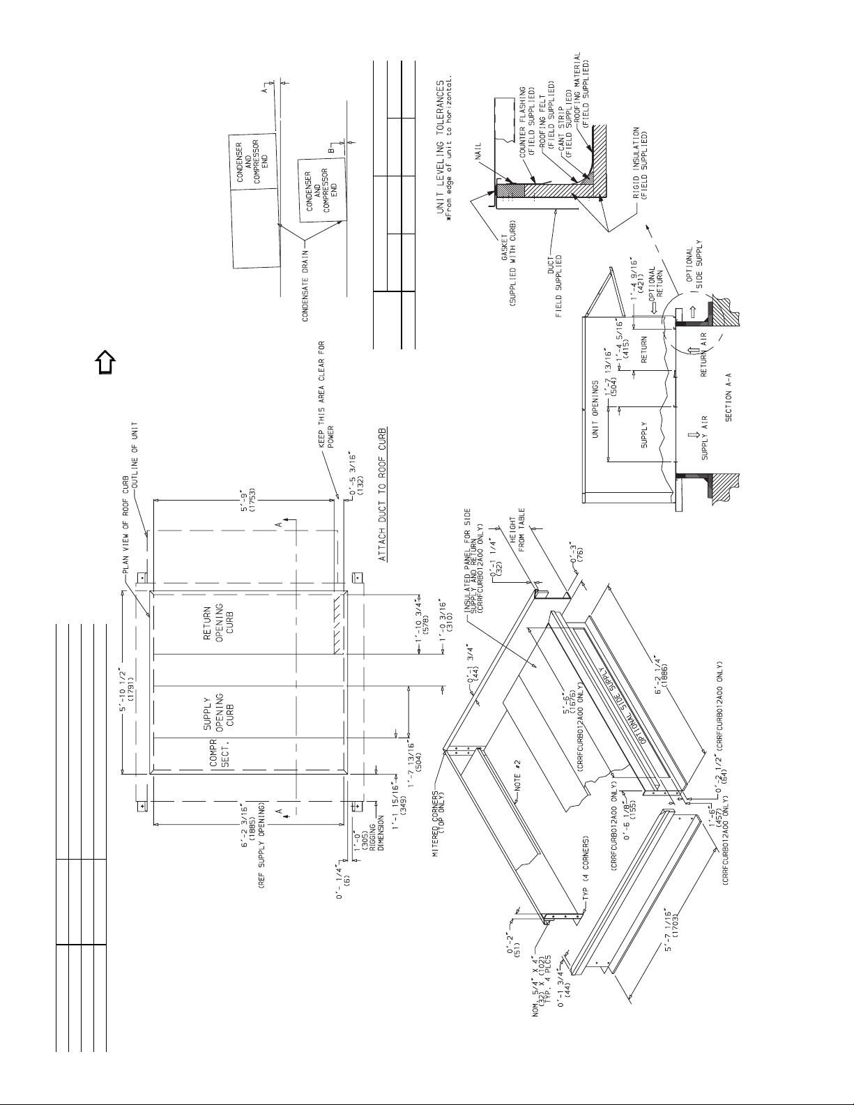
ROOF CURB — Assemble and install accessory roof curb or
horizontal adapter roof curb in accordance with instructions
shipped with the curb or horizontal adapter. Accessory roof
curb and horizontal adapter roof curb and information required
to field fabricate a roof curb or horizontal adapter roof curb are
shown in Fig. 1 and 2. Install insulation, cant strips, roofing,
and counter flashing as shown. Ductwork can be secured to
roof curb before unit is set in place.
Curb or adapter roof curb should be level. This is necessary
to permit unit drain to function properly. Unit leveling toler-
ance is
±
1
/
16
in. per linear ft in any direction. Refer to Accesso-
ry Roof Curb or Horizontal Adapter Roof Curb Installation In-
structions for additional information as required.
ALTERNATE UNIT SUPPORT — When the curb or adapter
cannot be used, support unit with sleepers using unit curb or
adapter support area. If sleepers cannot be used, support long
sides of unit with a minimum of 3 equally spaced 4-in. x 4-in.
pads on each side.
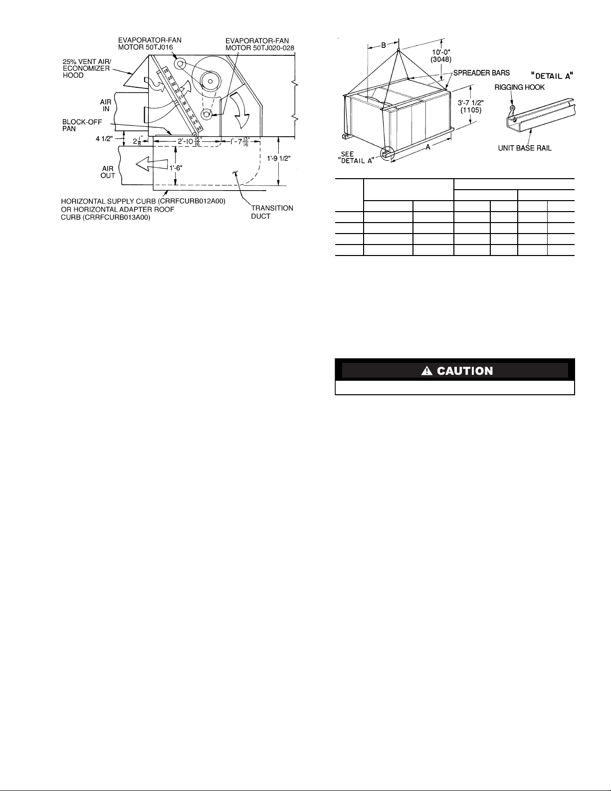
Step 2 — Rig and Place Unit —
Inspect unit for
transportation damage. File any claim with transportation
agency. Keep unit upright, and do not drop. Use spreader bars
over unit to prevent sling or cable damage. Rollers may be used
to move unit across a roof. Level by using unit frame as a refer-
ence; leveling tolerance is
±
1
/
16
in. per linear ft in any direc-
tion. See Fig. 3 for additional information. Unit weight is
shown in T able 1.
Four lifting holes are provided in ends of unit base rails as
shown in Fig. 3. Refer to rigging instructions on unit.
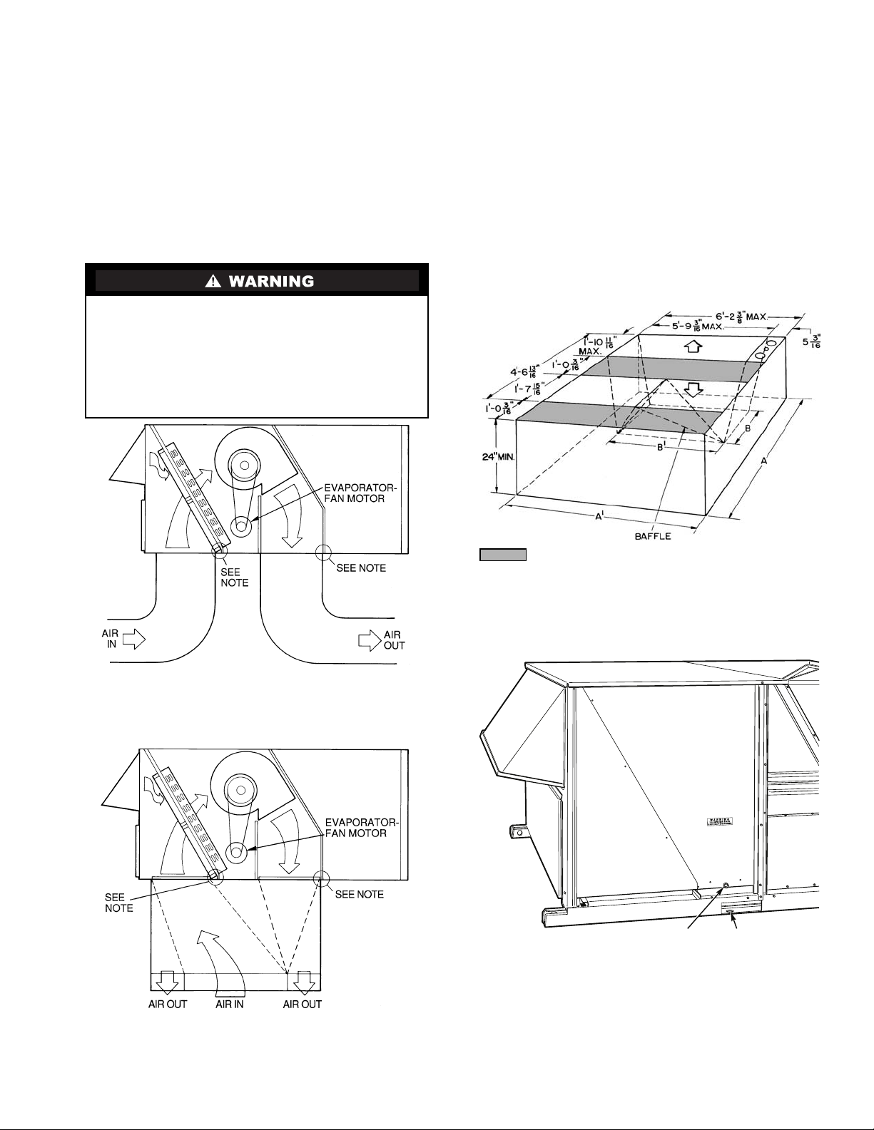
POS ITIONI NG — Provide clearance around and above unit
for airflow, safety, and service access (Fig. 4 and 5).
Do not install unit in an indoor location. Do not locate air in-
lets near exhaust vents or other sources of contaminated air.
Although unit is weatherproof, guard against water from
higher level runoff and overhangs.
ROOF MOUNT — Check building codes for weight distribu-
tion requirements.
Before performing service or maintenance operations on
unit, turn off main power switch to unit. Electrical shock
could cause personal injury.
IMPORTANT: Units have high ambient operating lim-
its. If limits are exceeded, the unit will automatically
lock the compressor out of operation. Manual r eset will
be required to restart the compressor.
IMPORTANT: The gasketing of the unit to the roof curb
or adapter roof curb is critical for a leak-proof seal.
Install gasket supplied with the roof curb or adapter roof
curb as shown in Fig. 1. Improperly applied gasket can
result in air leaks and poor unit performance.
50TJ016-028
Single-Package Rooftop Units
Electric Cooling with Electric Heat Option
2
NOTES:
1. Roof curb accessory is shipped disassembled.
2. Insulated panels: 1
″
thick neoprene coated 1
1
/
2
lb density.
3. Dimensions in ( ) are in millimeters.
4. Direction of airflow.
5. Roof curb: 16 ga. (VA03-56) stl.
6.
A 90 degree elbow must be installed on the supply ductwork
below the unit discharge for units equipped with electric
heaters.
NOTE: To prevent the hazard of stagnant water build-up in the drain
pan of the indoor section, unit can only be pitched as shown.
DIMENSIONS* (degrees and inches)
UNIT
AB
Deg.in.Deg.in.
ALL
.28 .45 .28 .43
PKG. NO. REF. CURB HEIGHT DESCRIPTION
CRRFCURB010A00 1
′
-2
″
(305) Standard Curb 14
″
High
CRRFCURB011A00 2
′
-0
″
(610) Standard Curb for Units Requiring High Installation
CRRFCURB012A00 2
′
-0
″
(610) Side Supply and Return Curb for High Installation
Fig. 1 — Roof Curb Details
3
NOTE: For preassembled horizontal adapter roof curb part no.
CRRFCURB013A00, the accessory kit includes a factory-designed,
high-static, transition duct. For horizontal curb part no.
CRRFCURB012A00, a field-supplied transition duct is required.
Fig. 2 — Horizontal Adapter Roof Curb
and Roof Curb
NOTES:
1. Dimensions in ( ) are in millimeters.
2. Refer to Fig. 4 and 5 for unit operating weights.
3. Remove boards at ends of unit and runners prior to rigging.
4. Rig by inserting hooks into unit base rails as shown. Use corner
post from packaging to protect coil from damage. Use bumper
boards for spreader bars.
5. Weights do not include optional EconoMi$er. See Fig. 4 and 5 for
EconoMi$er weight. See Table 1 for MoistureMiser weight.
6. Weights given are for aluminum evaporator and condenser coil
plate fins.
Fig. 3 — Rigging Details
UNIT
50TJ
MAXIMUM
SHIPPING WEIGHT
DIMENSIONS
AB
Lb Kg Ft-in. mm Ft-in. mm
016
1550 703 6-11
1
/
2
2121 4- 0 1219
020
1650 748 6-11
1
/
2
2121 3-10 1168
024
1700 771 6-11
1
/
2
2121 3- 7 1092
028
1850 839 6-11
1
/
2
2121 3- 5 1041
All panels must be in place when rigging.
4
POWER EXHAUST/BAROMETRIC RELIEF
(ACCESSORY ONLY)
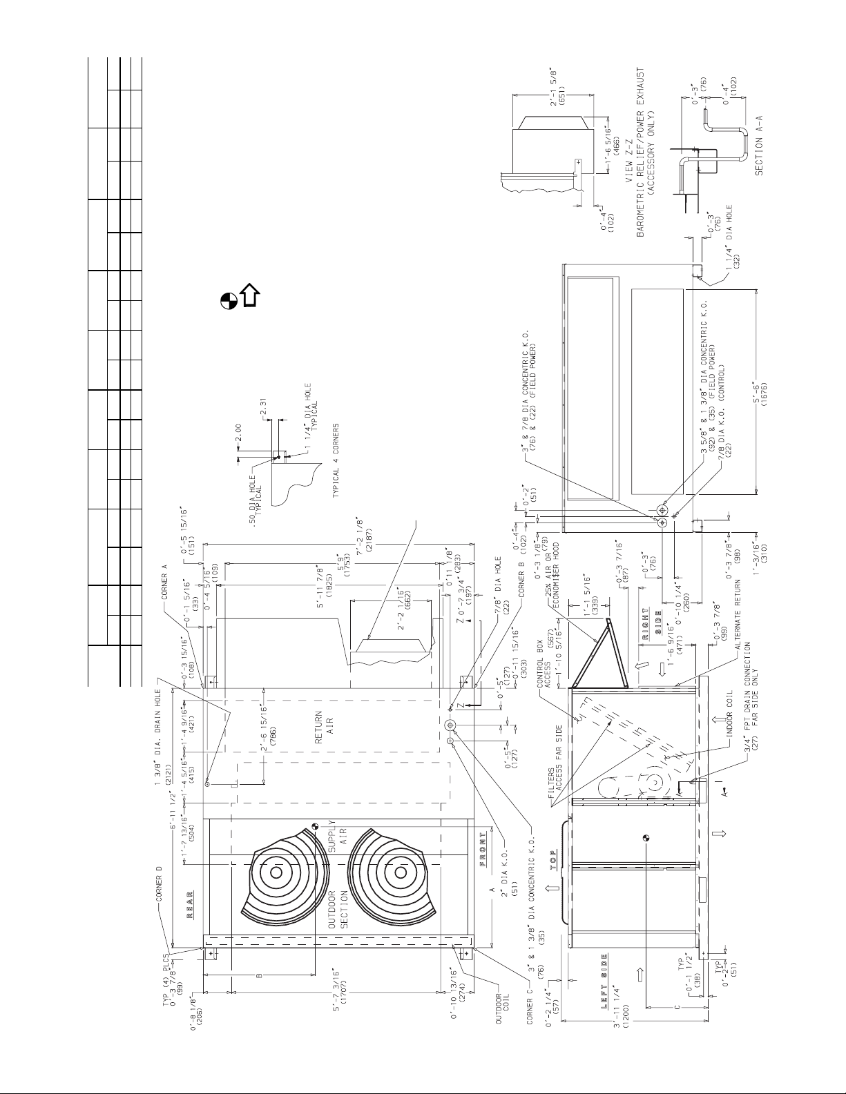
Fig. 4 — Base Unit Dimensions, 50TJ016,020
UNIT
STD UNIT
WEIGHT
ECONOMI$ER
WEIGHT
CORNER
(A)
CORNER
(B)
CORNER
(C)
CORNER
(D)
DIM A DIM B DIM C
Lb Kg Lb Kg Lb Kg Lb Kg Lb Kg Lb Kg Ft-in. mm Ft-in. mm Ft-in. mm
50TJ016
1550 703 80 36.3 391 177 365 166 384 174 410 186 3-5 1041 3-6 1067 1-10 559
50TJ020
1650 748 80 36.3 399 181 384 174 402 182 439 199 3-4 1016 3-6 1067 1- 8 508
NOTES:
1. Refer to print for roof curb accessory dimensions.
2. Dimensions in [ ] are in millimeters.
3. Center of gravity.
4. Direction of airflow.
5. Ductwork to be attached to accessory roof curb only.
6. Minimum clearance:
•
Rear: 7
′
-0
″
(2134) for coil removal. This dimension can be
reduced to 4
′
-0
″
(1219) if conditions permit coil removal from the
top.
•
Left side: 4
′
-0
″
(1219) for proper condenser coil airflow.
•
Front: 4
′
-0
″
(1219) for control box access.
•
Right side: 4
′
-0
″
(1219) for proper operation of damper and
power exhaust if so equipped.
•
Top: 6
′
-0
″
(1829) to assure proper condenser fan operation.
•
Local codees or jurisdiction may prevail.
7. With the exception of clearance for the condenser coil and the
damper/power exhaust as stated in Note #6, a removable fence or
barricade requires no clearance.
8. Dimensions are from outside of corner post. Allow 0
′
-
5
/
16
″
(8) on
each side for top cover drip edge.
9. See drawing 50TJ500352 for service option details.
5
POWER EXHAUST/BAROMETRIC RELIEF
(ACCESSORY ONLY)
Fig. 5 — Base Unit Dimensions, 50TJ024,028
UNIT
STD UNIT
WEIGHT
ECONOMI $ER
WEIGHT
CORNER
(A)
CORNER
(B)
CORNER
(C)
CORNER
(D)
DIM ADIM BDIM C
Lb Kg Lb Kg Lb Kg Lb Kg Lb Kg Lb Kg Ft-in. mm Ft- in. mm Ft-in. mm
50TJ024
1700 771 80 36.3 419 190 394 179 425 193 463 210 3-4 1016 3-5 1041 1-8 508
50TJ028
1850 839 80 36.3 428 194 412 187 511 232 499 226 3-2 965 3-7 1092 1-8 508
NOTES:
1. Refer to print for roof curb accessory dimensions.
2. Dimensions in [ ] are in millimeters.
3. Center of gravity.
4. Direction of airflow.
5. Ductwork to be attached to accessory roof curb only.
6. Minimum clearance:
•
Rear: 7
′
-0
″
(2134) for coil removal. This dimension can be
reduced to 4
′
-0
″
(1219) if conditions permit coil removal from the
top.
•
Left side: 4
′
-0
″
(1219) for proper condenser coil airflow.
•
Front: 4
′
-0
″
(1219) for control box access.
•
Right side: 4
′
-0
″
(1219) for proper operation of damper and
power exhaust if so equipped.
•
Top : 6
′
-0
″
(1829) to assure proper condenser fan operation.
•
Local codees or jurisdiction may prevail.
7. With the exception of clearance for the condenser coil and the
damper/power exhaust as stated in Note #6, a removable fence or
barricade requires no clearance.
8. Dimensions are from outside of corner post. Allow 0
′
-
5
/
16
″
(8) on
each side for top cover drip edge.
9. See drawing 50TJ500352 for service option details.
6
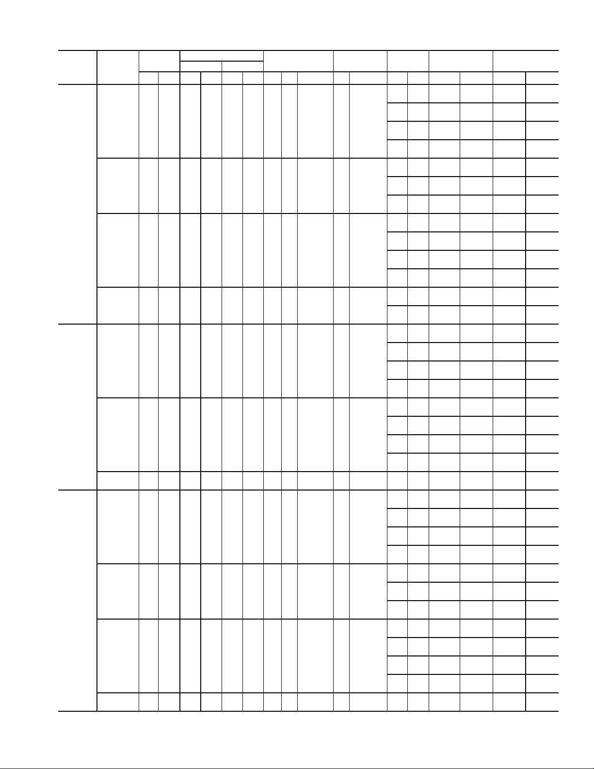
Table 1 — Physical Data
LEGEND
*Circuit 1 uses the lower por tion of condenser coil and lower portion of evap-
orator coils; and Circuit 2 uses the upper portion of both coils.
†The 50TJ028 units requires 2-in. industrial-grade filters capable of handling
face velocities of up to 625 ft/min (such as American Air Filter no. 5700 or
equivalent).
NOTE: The 50TJ016-028 units have a low-pressure switch (standard) located
on the suction side.
UNIT 50TJ
016
020 024 028
208/230, 460 v 575 v
NOMINAL CAPACITY (tons) 15 18 20 25
OPERATING WEIGHT 1550 1650 1700 1850
EconoMi$er 80
80 80 80
MoistureMiser Dehumidification
Package
40
40 40 40
COMPRESSOR/MANUFACTURER Scroll, Copeland
Quantity...Model (Ckt 1, Ckt 2)
2...ZR94KC
50, 50
2
81, 81
1...ZR108KC,
1...ZR94KC
1...ZR125KC,
1...ZR108KC
1...ZR16M3,
1...ZR125KC
Capacity Stages (%) 55, 45 55, 45 60, 40
Number of Refrigerant Circuits 22 2
Oil (oz) (Ckt 1, Ckt 2) 106, 81 106,106 136, 106
REFRIGERANT TYPE R-22
Expansion Device TXV
Operating Charge (lb-oz)
Circuit 1* 10-10
10-10
15-5 16-0 20-13
Circuit 2 12-3 13-6 13- 0
CONDENSER COIL Cross-Hatched
3
/
8
-in. Copper Tubes, Aluminum Lanced,
Aluminum Pre-Coated, or Copper Plate Fins
Rows...Fins/in. 2...17
21.7
3...15 3...15 4...15
Total Face Area (sq ft) 21.7 21.7 21.7
CONDENSER FAN Propeller Type
Nominal Cfm 10,500 10,500 14,200 14,200
Quantity...Diameter (in.) 3...22 3...22 2...30 2...30
Motor Hp...Rpm
1
/
2
...1050
1
/
2
...1050 1...1075 1...1075
Watts Input (Total) 1100 1100 3400 3400
EVAPORATOR COIL Cross-Hatched
3
/
8
-in. Copper Tubes, Aluminum Lanced or
Copper Plate Fins, Face Split
Rows...Fins/in. 2...17 3...15 3...15 4...15
Total Face Area (sq ft) 17.5 17.5 17.5 17.5
EVAPORATOR FAN Centrifugal Type
Quantity...Size (in.) 2...10 x 10 2...10 x 10 2...12 x 12 2...12 x 12 2...12 x 12
Type Drive Belt Belt Belt Belt Belt
Nominal Cfm 6000 6000 7200 8000 10,000
Motor Hp 3.7 3.0 5 7.5 10
Motor Nominal Rpm 1725 1725 1745 1745 1740
Maximum Continuous Bhp 4.25 3.45 5.90
8.7 [208/230, 575 v]
9.5 [460 v]
10.2 [208/230, 575 v]
11.8 [380, 460 v]
Motor Frame Size 56H 56H 184T 213T 215T
Nominal Rpm High/Low ——— — —
Fan r/s Range Low-Medium Static 891-1179 1159-1429 910-1095 1002-1225 1066-1283
High Static 1227-1550 — 1069-1287 1193-1458 1332-1550
Motor Bearing Type Ball Ball Ball Ball Ball
Maximum Allowable Rpm 1550 1550 1550 1550 1550
Motor Pulley Pitch Diameter Low-Medium Static 3.1/4.1 4.3/5.3 4.9/5.9 5.4/6.6 4.9/5.9
Min/Max (in.) High Static 3.7/4.7 — 4.9/5.9 5.4/6.6 4.9/5.9
Nominal Motor Shaft Diameter (in.)
7
/
8
7
/
8
1
1
/
8
1
3
/
8
1
3
/
8
Fan Pulley Pitch Diameter (in.) Low-Medium Static 6.0 6.4 9.4 9.4 8.0
High Static 5.2 — 8.0 7.9 6.4
Nominal Fan Shaft Diameter (in.) 1
3
/
16
1
3
/
16
1
7
/
16
1
7
/
16
1
7
/
16
Belt, Quantity...Type...Length (in.) Low-Medium Static 1...BX...42 1...BX...45 1...BX...50 1...BX...53 2...BX...50
High Static 1...BX...42 — 1...BX...48 1...BX...50 2...BX...47
Pulley Center Line Distance (in.) 13.5-15.5 13.5-15.5 13.3-14.8 14.6-15.4 14.6-15.4
Speed Change per Full Turn of
Movable Pulley Flange (rpm)
Low-Medium Static 48 44 37 37 36
High Static 55 — 34 44 45
Movable Pulley Maximum Full Turns
From Closed Position 666 6 6
Factory Speed 3.5 3.5 3.5 3.5 3.5
Factory Speed Setting (rpm Low-Medium Static 1035 1296 1002 1120 1182
High Static 1389 — 1178 1328 1470
Fan Shaft Diameter at Pulley (in.) 1
3
/
16
1
3
/
16
1
7
/
16
1
7
/
16
1
7
/
16
HIGH-PRESSURE SWITCH (psig)
Cutout 426
Reset (Auto) 320
LOW-PRESSURE SWITCH (psig)
Cutout 27
Reset (Auto) 44
FREEZE PROTECTION THERMOSTAT (F)
Opens 30
±
5
Closes 45
±
5
OUTDOOR-AIR INLET SCREENS Cleanable
Quantity...Size (in.) 2...20 x 25 x 1
1...20 x 20 x 1
RETURN-AIR FILTERS Throwaway†
Quantity...Size (in.) 4...20 x 20 x 2
4...16 x 20 x 2
POWER EXHAUST
1
/
2
Hp, 208/230-460 v Motor Direct Drive, Propeller-Fan (Factory-Wired for 460 v)
Bhp — Brake Horsepower
TXV — Thermostatic Expansion Valve
7
Step 3 — Field Fabricate Ductwork —
Secure all
ducts to building structure. Use flexible duct connectors be-
tween unit and ducts as required. Insulate and weatherproof all
external ductwork, joints, and roof openings with counter
flashing and mastic in accordance with applicable codes.
Ducts passing through an unconditioned space must be in-
sulated and covered with a vapor barrier.
The 50TJ units with electric heat require a 1-in. clearance
for the first 24 in. of ductwork.
Outlet grilles must not lie directly below unit discharge.
NOTE: A 90-degree elbow must be provided in the ductwork
to comply with UL (Underwriters’ Laboratories) codes for use
with electric heat.
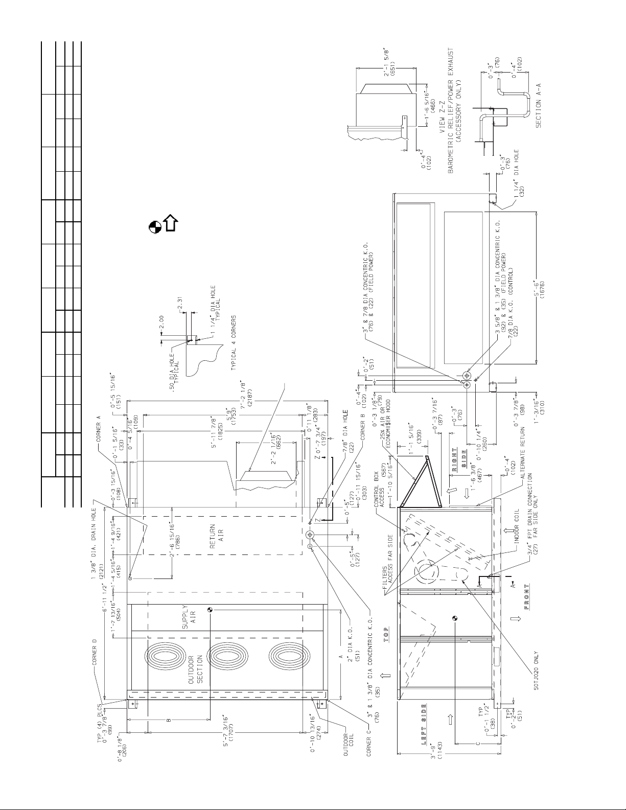
Step 4 — Make Unit Duct Connections —
Unit
is shipped for through-the-bottom duct connections. Ductwork
openings are shown in Fig. 6. Field-fabricated concentric duct-
work may be connected as shown in Fig. 7 and 8. Attach all
ductwork to roof curb and roof curb basepans. Refer to installa-
tion instructions shipped with accessory roof curb for more
information.
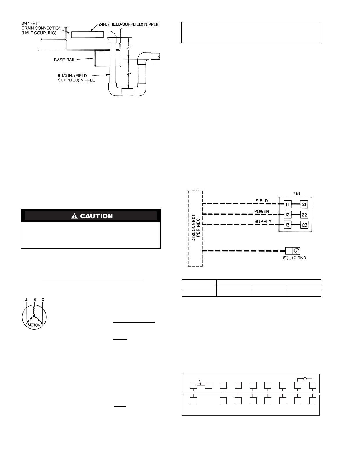
Step 5 — Trap Condensate Drain —
See Fig. 4, 5,
and 9 for drain location. Plug is provided in drain hole and
must be removed when unit is operating. One
3
/
4
-in. half-
coupling is provided inside unit evaporator section for conden-
sate drain connection. An 8
1
/
2
in. x
3
/
4
-in. diameter nipple and a
2-in. x
3
/
4
-in. diameter pipe nipple are coupled to standard
3
/
4
-in. diameter elbows to provide a straight path down through
holes in unit base rails (see Fig. 10). A trap at least 4-in. deep
must be used.
For vertical supply and return units, tools or parts could
drop into ductwork and cause an injury. Install a 90 degree
turn in the return ductwork between the unit and the condi-
tioned space. If a 90 degree elbow cannot be installed, then
a grille of sufficient strength and density should b e installed
to prevent objects from falling into the conditioned space.
Due to electric heater, supply duct will require 90 degree
elbow.
NOTE: Do not drill in this area; damage to basepan may result in
water leak.
Fig. 6 — Air Distribution — Thru-the-Bottom
(50TJ020-028 Shown)
NOTE: Do not drill in this area; damage to basepan may result in
water leak.
Fig. 7 — Concentric Duct Air Distribution
(50TJ020-028 Shown)
3/4" FPT DRAIN
CONNECTION
1-3/8"
DRAIN HOLES
Shaded area indicates block-off panels.
NOTE: Dimensions A, A
′,
and B, B
′
are obtained from field-supplied
ceiling diffuser.
Fig. 8 — Concentric Duct Details
Fig. 9 — Condensate Drain Details
(50TJ016,020 Shown)
8
Step 6 — Make Electrical Connections
FIEL D POWER SUP PLY — Unit is factory wired for volt-
age shown on nameplate.
When installing units, provide a disconnect, per NEC
(National Electrical Code) requirements, of adequate size
(T able 2).
All field wiring must comply with NEC and local
requirements.
Route power lines through control box access panel or unit
basepan (Fig. 4 and 5) to connections as shown on unit wiring
diagram and Fig. 11.
Operating voltage to compressor must be within voltage
range indicated on unit nameplate. On 3-phase units, voltages
between phases must be balanced within 2% and the current
must be balanced within 10%.
Use the following formula to determine the percentage of
voltage imbalance.
Percentage of Voltage Imbalance
EXAMPLE: Supply voltage is 460-3-60.
AB = 452 v
BC = 464 v
AC = 455 v
Determine maximum deviation from average voltage:
(AB) 457 – 452 = 5 v
(BC) 464 – 457 = 7 v
(AC) 457 – 455 = 2 v
Maximum deviation is 7 v.
Determine percent voltage imbalance:
= 1.53%
This amount of phase imbalance is satisfactory as it is be-
low the maximum allowable 2%.
Unit failure as a result of operation on improper line voltage
or excessive phase imbalance constitutes abuse and may cause
damage to electrical components.
FIELD CONTR OL WIRING — Install a Carrier-approved
accessory thermostat assembly according to the installati on in-
structions included with the accessory. Locate thermostat as-
sembly on a solid wall in the conditioned space to sense aver-
age temperature.
Route thermostat cable or equivalent single leads of no. 18
A WG (American Wire Gage) colored wire from subbase termi-
nals through conduit in unit to low-voltage connections as
shown on unit label wiring diagram and in Fig. 12.
NOTE: For wire runs up to 50 ft, use no. 18 AWG insulated
wire (35 C minimum). For 50 to 75 ft, use no. 16 AWG insu-
lated wire (35 C minimum). For over 75 ft, use no. 14 AWG
insulated wire (35 C minimum). All wire larger than no. 18
AWG cannot be direct ly connected to the thermostat and will
require a junction box and splice at the thermostat.
Set heat anticipator settings as indicated in Tabl e 3. Settings
may be changed slightly to provide a greater degree of comfort
for a particular installation.
The correct power phasing is critical in the operation of the
scroll compressors. An incorrect phasing will cause the
compressor to rotate in the wrong direction. This may lead
to premature compressor failure.
= 100 x
max voltage deviation from average voltage
average voltage
A verage Voltage =
455 + 464 + 455
3
=
1371
3
= 457
Percentage of Voltage Imbalance = 100 x
7
457
IMPORTANT: If the supply voltage phase imbalance is
more than 2%, contact your local electric utility com-
pany immediately.
Fig. 10 — Make Electrical Connections
TB1 MAXIMUM WIRE SIZE
LEGEND
Fig. 11 — Field Power Wiring Connections
UNIT
50TJ
VOLTAGE
208/230,380 460 575
All
350 kcmil 2/0 2/0
EQUIP —
Equipment
GND —
Ground
kcmil —
Thousand Circular Mils
NEC —
National Electrical Code
TB —
Terminal Block
RH
RC
Y1 Y2
W1
W2
GC
X
L
X
C
G
W2
W1Y2
Y1
R
REMOVABLE JUMPER
RED
BLU
PNK
ORN
VIO
BLK
BRN
WHT
THERMOSTAT ASSEMBLY
UNIT LOW-VOLTAGE CONNECTIONS
Fig. 12 — Field Control Thermostat Wiring
9
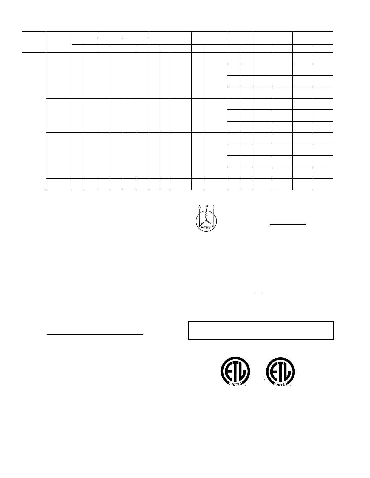
Table 2 — Electrical Data
UNIT
50TJ
NOMINAL
VOLTAGE
(3 Ph,
60 Hz)
VOLTAGE
RANGE
COMPRESSOR
OFM IFM
POWER
EXHAUST
ELECTRIC
HEAT*
POWER
SUPPLY
No. 1 No. 2
Min Max RLA LRA RLA LRA Qty Hp FLA (ea) Hp FLA FLA LRA kW FLA MCA MOCP†
016
(15 Tons)
208/230 187 253 28.8 195 28.8 195 3 0.5 1.7 3.7 10.5/11.0
—— — — 81/81 100/100
4.6 18.8 ——85/86 110/110
——26/34 71/82 102/116 110/125
4.6 18.8 26/34 71/82 108/122 110/125
——42/56 117/135 159/149 175/175
4.6 18.8 42/56 117/135 165/155 175/175
——56/75** 156/180 169/194 200/225
4.6 18.8 56/75** 156/180 175/200 200/225
380 342 418 15.0 123 15.0 123 3 0.5 1.7 3.7 3.9
—— — — 43 50
2.3 6.0 —— 45 60
—— 20 30 43 50
2.3 6.0 20 30 46 60
—— 35 52 70 80
2.3 6.0 35 52 73 80
460 414 508 14.7 95 14.7 95 3 0.5 0.8 3.7 4.8
—— — — 40 50
2.3 6.0 —— 43 50
—— 32 39 55 60
2.3 6.0 32 39 58 60
—— 55 66 72 80
2.3 6.0 55 66 75 80
—— 80** 96 102 110
2.3 6.0 80** 96 105 110
575 518 633 10.8 80 10.8 80 3 0.5 0.75 3.0 3.9
—— — — 30 40
2.1 4.8 —— 32 40
—— 50** 48 67 70
2.1 4.8 50** 48 70 70
020
(18 Tons)
208/230 187 253 30.1 225 28.8 195 3 0.5 1.7 5.0 15.8/15.8
—— — — 87/87 110/110
4.6 18.8 ——92/92 110/110
——26/34 71/82 109/122 110/125
4.6 18.8 26/34 71/82 114/128 125/150
——42/56 117/135 166/155 175/175
4.8 18.8 42/56 117/135 172/161 175/175
——56/75** 156/180 176/200 200/225
4.6 18.8 56/75** 156/180 182/206 200/225
460 414 508 15.5 114 14.7 95 3 0.5 0.8 5.0 7.9
—— — — 44 50
2.3 6.0 —— 47 60
—— 32 39 59 60
2.3 6.0 32 39 61 70
—— 55 66 76 90
2.3 6.0 55 66 79 90
—— 80** 96 106 125
2.3 6.0 80** 96 109 125
575 518 633 12.1 80 10.8 80 3 0.5 0.75 5.0 6.0
—— — — 34 40
2.1 4.8 —— 36 40
024
(20 Tons)
208/230 187 253 37.8 239 30.1 225 2 1 6.6 7.5 25.0/25.0
—— — — 116/116 150/150
4.6 18.8 ——120/120 150/150
——26/34 71/82 120/134 150/150
4.6 18.8 26/34 71/82 126/140 150/150
——42/56 117/135 178/166 200/175
4.6 18.8 42/56 117/135 183/172 200/175
——56/75** 156/180 187/211 200/225
4.6 18.8 56/75** 156/180 193/217 200/225
380 342 418 21.2 145 16.7 140 2 1 3.9 7.5 15.0
—— — — 66 80
2.3 6.0 —— 68 80
—— 20 30 66 80
2.3 6.0 20 30 68 80
—— 35 52 84 90
2.3 6.0 35 52 87 90
460 414 508 17.2 125 15.5 114 2 1 3.3 7.5 13.0
—— — — 57 70
2.3 6.0 —— 59 70
—— 32 39 65 70
2.3 6.0 32 39 68 70
—— 55 66 82 90
2.3 6.0 55 66 85 90
—— 80** 96 112 125
2.3 6.0 80** 96 115 125
575 518 633 12.4 80 12.1 80 2 1 3.4 7.5 10.0
—— — — 44 50
2.1 4.8 —— 46 50
10
Table 2 — Electrical Data (cont)
LEGEND
*Heater capacity (kW) is based on heater voltage of 208 v, 240 v,
380 v, 480 v, and 575 v. Heaters are rated at 240 v, 380 v, 480 v, or
600 v. If power distribution voltage to unit varies from rated heater
voltage, heater kW will vary accordingly.
†Fuse or HACR circuit breaker.
**Heaters are field installed only.
NOTES:
1. In compliance with NEC requirements for multimotor and combi-
nation load equipment (refer to NEC Articles 430 and 440), the
overcurrent protective device for the unit shall be fuse or HACR
breaker. Canadian units may be fuse or circuit breaker.
2.
Unbalanced 3-Phase Supply Voltage
Never operate a motor where a phase imbalance in supply volt-
age is greater than 2%.
Use the following formula to determine
the percent of voltage imbalance.
% Voltage Imbalance
Example: Supply voltage is 460-3-60.
AB = 452 v
BC = 464 v
AC = 455 v
= 457
Determine maximum deviation from average voltage.
(AB) 457 – 452 = 5 v
(BC) 464 – 457 = 7 v
(AC) 457 – 455 = 2 v
Maximum deviation is 7 v.
Determine percent of voltage imbalance.
% Voltage Imbalance = 100 x
= 1.53%
This amount of phase imbalance is satisfactory as it is below the
maximum allowable 2%.
3. MCA calculation for units with electric heaters over 50 kW =
(1.25 x IFM amps) + (1.00 x heater FLA).
UNIT
50TJ
NOMINAL
VOLTAGE
(3 Ph,
60 Hz)
VO LTAG E
RANGE
COMPRESSOR
OFM IFM
POWER
EXHAUST
ELECTRIC
HEAT*
POWER
SUPPLY
No. 1 No. 2
Min Max RLA LRA RLA LRA Qty Hp FLA (ea) Hp FLA FLA LRA kW FLA MCA MOCP†
028
(25 Tons)
208/230 187 253 41.0 350 37.8 239 2 1 6.6 10.0 28.0/28.0
—— — — 130/130 150/150
4.6 18.8 ——135/135 175/175
——26/34 71/82 130/138 150/150
4.6 18.8 26/34 71/82 135/143 175/175
——42/56 117/135 181/170 200/175
4.6 18.8 42/56 117/135 187/176 200/200
— - 56/75** 156/180 191/215 200/225
4.6 18.8 56/75** 156/180 197/221 200/225
380 342 418 21.8 151 21.2 145 2 1 3.9 10.0 17.0
—— — — 73 90
2.3 6.0 —— 76 90
—— 20 30 73 90
2.3 6.0 20 30 76 90
—— 35 52 87 90
2.3 6.0 35 52 90 90
460 414 508 21.8 158 17.2 125 2 1 2.8 10.0 14.6
—— — — 66 80
2.3 6.0 —— 68 80
—— 32 39 67 80
2.3 6.0 32 39 70 80
—— 55 66 84 90
2.3 6.0 55 66 87 100
—— 80** 96 114 125
2.3 6.0 80** 96 117 125
575 518 633 17.3 125 12.4 80 2 1 3.4 10.0 13.0
—— — — 54 70
2.1 4.8 —— 56 70
FLA —
Full Load Amps
HACR—
Heating, Air Conditioning and Refrigeration
IFM —
Indoor (Evaporator) Fan Motor
LRA —
Locked Rotor Amps
MCA —
Minimum Circuit Amps
MOCP—
Maximum Overcurrent Protection
NEC —
National Electrical Code
OFM —
Outdoor (Condenser) Fan Motor
RLA —
Rated Load Amps
= 100 x
max voltage deviation from average voltage
average voltage
Average Voltage =
452 + 464 + 455
3
=
1371
3
IMPORTANT: If the supply voltage phase imbalance is
more than 2%, contact your local electric utility company
immediately.
7
457
11
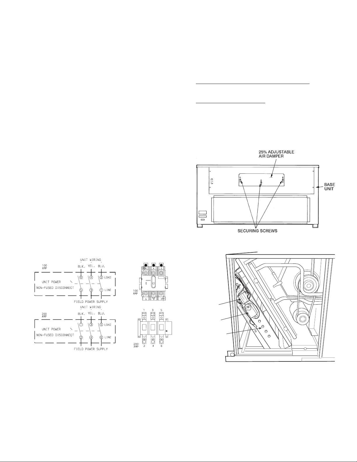
OPTIONAL NON-FUSED DISCONNECT — On units with
the optional non-fused disconnect, incoming power will be
wired into the disconnect switch. Refer to Fig. 13 for wiring
for 100 and 200 amp disconnect switches. Units with an
MOCP under 100 will use the 100 amp disconnect switch.
Units with an MOCP over 100 will use the 200 amp discon-
nect switch. Refer to the applicable disconnect wiring diagram.
To prevent breakage during shipping, the disconnect han-
dle and shaft are shipped and packaged inside the unit control
box. Install the disconnect handle before unit operation. To in-
stall the handle and shaft, perform the following procedure:
1. Ope n the control box door and remove the handle and
shaft from shipping location.
2. Loosen the A llen bolt located on the disconnect switch.
The bolt is located on the square hole and is used to hold
the shaft in place. The shaft cannot be inserted until the
Allen bolt is moved.
3. Insert the disconnect shaft into the square hole on the dis-
connect switch. The end of the shaft is specially cut and
the shaft can only be inserted in the correct orientation.
4. Tighten the Allen bolt to lock the shaft into position.
5. Close the control box door.
6. Attach the handle to the external access door with the two
screws provided. When the handle is in the ON position,
the handle will be vertical. When the handle is in the OFF
position, the handle will be horizontal.
7. Turn the handle to the OFF position and close the door.
The handle should fit over the end of the shaft when t he
door is closed.
8. The ha ndle must be in the OFF position to open the con-
trol box door.
OPTIONAL CONVENIENCE OUTLET — On units with
optional convenience outlet, a 115-v GFI (ground fault inter-
rupt) convenience outlet receptacle is provided for field wiring.
Field wiring should be run through the
7
/
8
-in. knockout pro-
vided in the basepan near the return air opening.
Step 7 — Make Outdoor-Air Inlet Adjustments
MANUAL OUTDOOR-AIR DAMPER — All units (except
those equipped with a factory-installed economizer) have a
manual outdoor-air damper to provide ventilation air. Damper
can be preset to admit up to 25% outdoor air into return-ai r
compartment. To adjust, loosen securing screws and move
damper to desired setting. Then retighten screws to secure
damper (Fig. 14).
OPTIONAL ECONOMI$ER
EconoMi$er Motor Control Module (Fig. 15-17)
— Set the
ECONSP dial to the ‘ ‘D’’ setting (Fig. 16). The control module
is located on the EconoMi$er motor. See Fig. 15 and 17.
Damper Vent Position Setting
1. Set fan switch at ON position (continuous fan operation)
and close night switch if used.
2. Set system selector switch to OFF position.
3. Turn Min Pos (%) dial slowly until dampers assume de-
sired vent position.
Do not manually operate EconoMi$er
motor since damage to motor will result.
CONTROL
MODULE
ACTUATOR
ECONOMI$ER
Fig. 14 — 25% Outdoor-Air Section Details
Fig. 15 — EconoMi$er Damper Assembly
— End View
5L3 3L2 1L1 LINE
6T3 4T2 2T1 LOAD
NOTE: The disconnect takes the place of TB-1 as shown on the unit
wiring diagram label and the component arrangement label.
Fig. 13 — Optional Non-Fused Disconnect Wiring
 Loading...