


50PG03-07
50PG03---07
Single Package Rooftop Units
Electric Cooling with PURONR (R ---410A)
Refrigerant and COMFORTLinkt Controls
Installation Instructions
IMPORTANT: This installation instruction contains basic unit
installation information including installation of field control
devices. For information on unit start--up, service, and operation,
refer to the unit Controls, Start-- Up, Operation, Service, and
Troubleshooting Instructions also enclosed in the unit literature
packet.
TABLE OF CONTENTS
SAFETY CONSIDERATIONS 1.........................
INSTALLATION 4....................................
Step 1 -- Provide unit Support 4.........................
Step 2 -- Rig and Place Unit 4...........................
Step 3 -- Field Fabricate Ductwork 7......................
Step 4 -- Make Unit Duct Connections 7...................
Step 5 -- Install External Trap for Condensate Drain 7........
Step 6 -- Make Electrical Connections 8...................
Step 7 -- Install Outdoor Air Hoods (Units With
Economizer 22...............................
Step 8 -- Install All Accessories 22.......................
SAFETY CONSIDERATIONS
Installation and servicing of air-conditioning equipment can be
hazardous due to system pressure and electrical components. Only
trained and qualified service personnel should install, repair, or
service air-conditioning equipment.
Untrained personnel can perform the basic maintenance functions
of cleaning coils and filters and replacing filters. All other
operations should be performed by trained service personnel.
When working on air-conditioning equipment, observe precautions
in the literature, tags and labels attached to the unit, and other
safety precautions that may apply.
Follow all safety codes. Wear safety glasses and work gloves.
Recognize safety information. This is the safety--alert symbol
When you see this symbol on the unit and in instructions or
manuals, be alert to the potential for personal injury.
Understand the signal words DANGER, WARNING, and
CAUTION. These words are used with the safety--alert symbol.
DANGER identifies the most serious hazards which will result in
severe personal injury or death. WARNING signifies a hazard
which could result in personal injury or death. CAUTION is used
to identify unsafe practices which may result in minor personal
injury or product and property damage. NOTE is used to highlight
suggestions which will result in enhanced installation, reliability, or
operation.
!
WARNING
ELECTRICAL SHOCK HAZARD
Failure to follow this warning could cause personal
injury or death.
Before performing service or maintenance operations
on unit, turn off main power switch to unit and install
lockout tag.
!
WARNING
UNIT OPERATION AND SAFETY HAZARD
Failure to follow this warning could cause personal
injury, death and/or equipment damage.
Puron (R--410a) refrigerant systems operate at higher
pressures than standard R--22 systems. Do not use R--22
service equipment or components on Puron refrigerant
equipment.
!
WARNING
FIRE, EXPLOSION HAZARD
Failure to follow this warning could result in personal
injury, death and/or property damage.
1. Improper installation, adjustment, alteration, service,
or maintenance can cause property damage, personal
injury, or loss of life. Refer to the User’s Information
Manual provided with this unit for more details.
2. Do not store or use gasoline or other flammable
.
vapors and liquids in the vicinity of this or any other
appliance.
IMPORTANT: Units have high ambient operating limits. If limits
are exceeded, the units will automatically lock the compressor out
of operation. Manual reset will be required to restart the
compressor.
C07269
50PG03--07
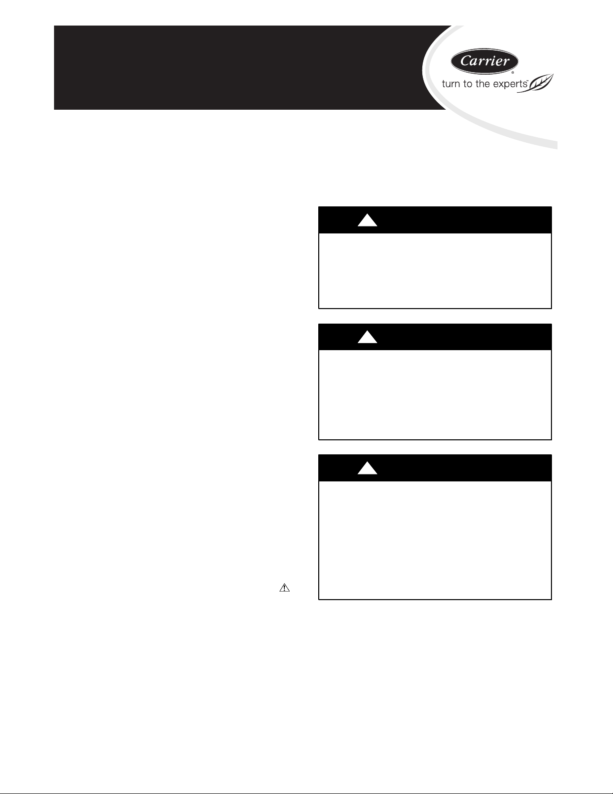
Fig. 1 -- Roof Curb Details
2
C07271
50PG03--07
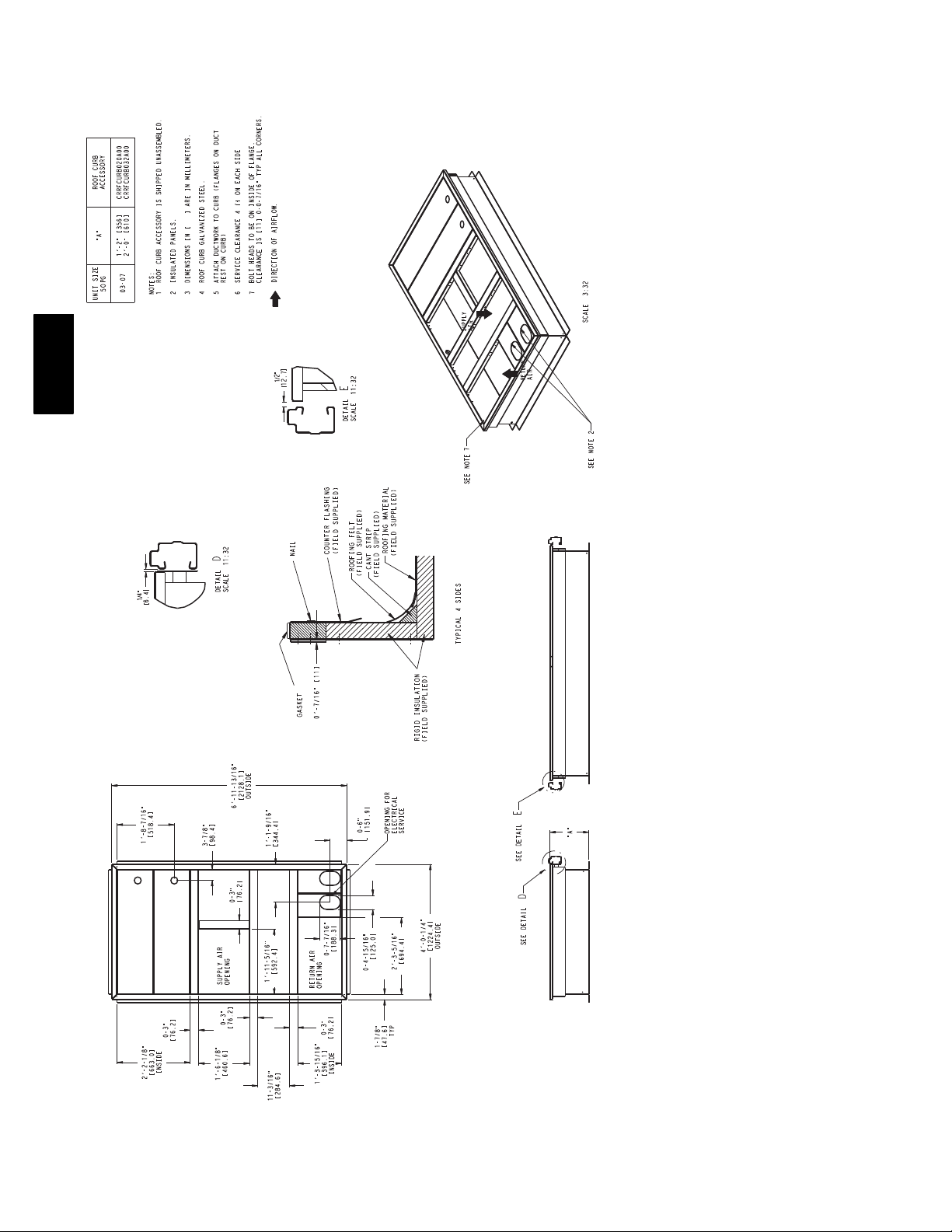
Fig. 2 -- Base Unit Dimensions
3

INSTALLATION
Step 1 — Provide Unit Support
Roof Curb
Assemble or install accessory roof curb in accordance with
instructions shipped with this accessory. (See Fig. 1.) Install
insulation, cant strips, roofing, and counter flashing as shown.
Ductwork can be installed to roof curb before unit is set in place.
Ductwork must be attached to curb and not to the unit. Curb must
be level. This is necessary to permit unit drain to function properly.
Unit leveling tolerance is 1/16--in. per linear ft in any direction.
Refer to Accessory Roof Curb Installation Instructions for
additional information as required. When accessory roof curb is
used, unit may be installed on class A, B, or C roof covering
material. Carrier roof curb accessories are for flat roofs or slab
mounting.
IMPORTANT: The gasketing of theunit to the roof curb is critical
for a watertight seal. Install gasket with the roof curb as shown in
Fig. 1. Improperly applied gasket can also result in air leaks and
poor unit performance. Do not slide unit to position on roof curb.
Alternate Unit Support
50PG03--07
When a curb cannot be used, install unit on a noncombustible
surface. Support unit with sleepers, using unit curb support area. If
sleepers cannot beused, support long sides of unit with a minimum
of 3 equally spaced 4--in. x 4--in. pads on each side.
Step 2 — Rig and Place Unit
Inspect unit for transportation damage. See Table 1 for physical
data. File any claim with transportation agency.
!
CAUTION
PERSONAL INJURY AND PROPERTY DAMAGE HAZARD
Failure to follow this caution may result in damage to roof.
All panels must be in place when rigging. Unit is not
designed for handling by fork truck.
Do not drop unit; keep upright. Use spreader bars over unit to
prevent sling or cable damage. Rollers may be used to move unit
across a roof. Level by using unit rail as a reference; leveling
tolerance is ± 1/16--in. per linear ft in any direction. See Fig. 3 for
additional information. Unit rigging weight is shown in Fig. 3.
Rigging holes are provided in the unit base rails as shown in Fig. 3.
Refer to rigging instructions on unit.
Positioning
Maintain clearance, per Fig. 2, around and above unit to provide
minimum distance from combustible materials, proper airflow, and
service access. See Fig. 4 for location of access panels.
Do not install unit in an indoor location. Do not locate air inlets
near exhaust vents or other sources of contaminated air.
Although unit is weatherproof, guard against water from higher
level runoff and overhangs.
After unit is in position, remove crating and polyethylene sheet.
Roof Mount
Check building codes for weight distribution requirements. Unit
operating weight is shown in Table 1.
Installation Onto Curb
The 50PG units are designed to fit on the accessory full perimeter
curb. In either case, correct placement of the unit onto the curb is
critical to operating performance. To aid in correct positioning,
place unit on roof curb to maintain 1/4--in. gap between the inside
of rail and roof curb on long sides and a 1/2--in. gap between the
inside of rail and roof curb on both duct and condenser ends. Refer
to Fig. 1 and 3, to assure proper duct opening alignment.
NOTE: Before positioning unit onto curb, refer to Step 5 -- Install
External Trap for Condensate Drain section concerning bottom
drain connection plug.
!
CAUTION
UNIT DAMAGE HAZARD
Failure to follow this caution may result in equipment
damage.
Do not slide unit to position when it is sitting on the curb.
Curb gasketing material may be damaged and leaks may
result.
Slab Mount (Horizontal Units Only)
Provide a level concrete slab that extends a minimum of 6--in.
beyond unit cabinet. Install a gravel apron in front of
condenser--coil air inlet to prevent grass and foliage from
obstructing airflow.
NOTE: Horizontal units may be installed on a roof curb if
required.
CAU OTI
ACCESS PANEL MUST BE IN PLACE WHEN RIGGING.
Hook rigging shackles through holes in base rail, as shown in
Detail A. Holes in base rails are centered around the unit
center of gravity. Use wooden top skid, when rigging, to
prevent rigging straps from damaging unit.
A B C D E MAX. WEIGHT
UNIT
SIZE
in. mm in. mm in. mm in. mm in. mm lb kg
03-07 77.9 1978 36-54 914-1371 44.8 1139 42.0 1067 23.5 597 1156 52
N- NOTICE TO R GGERS:I
Fig. 3 -- 50PG Rigging Label
4
5
C07270
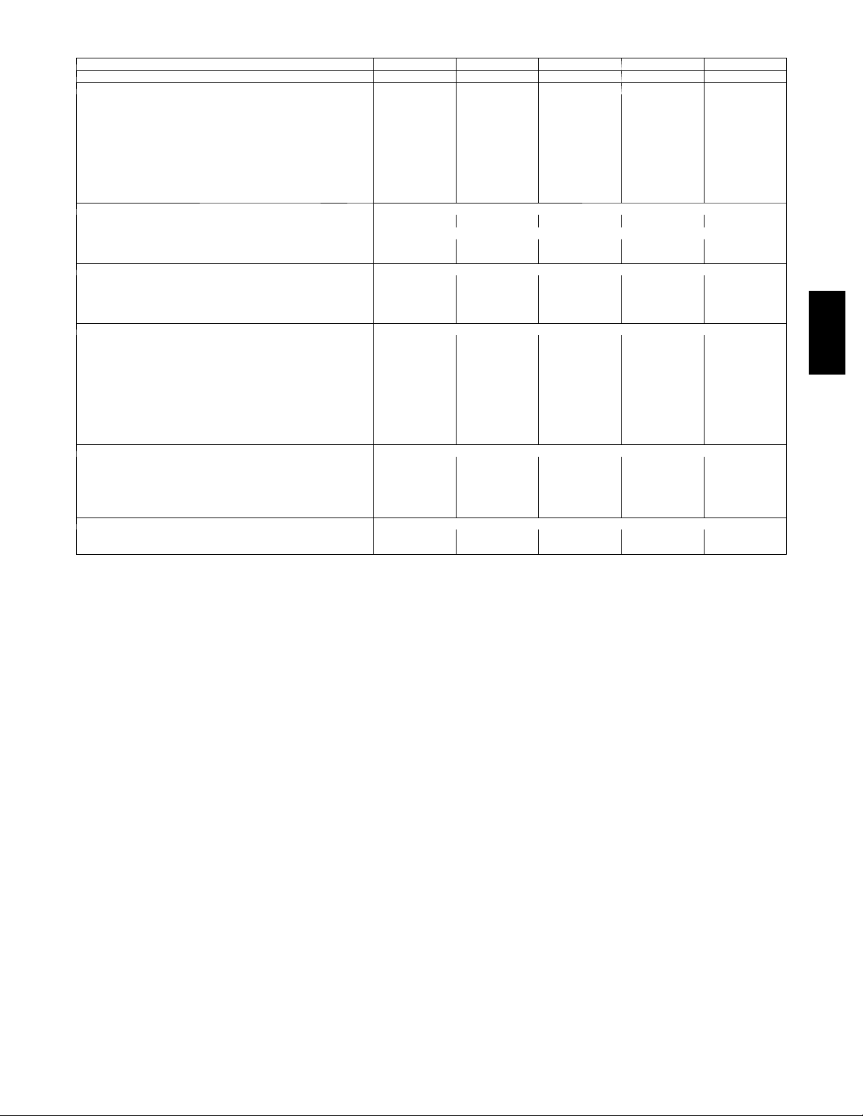
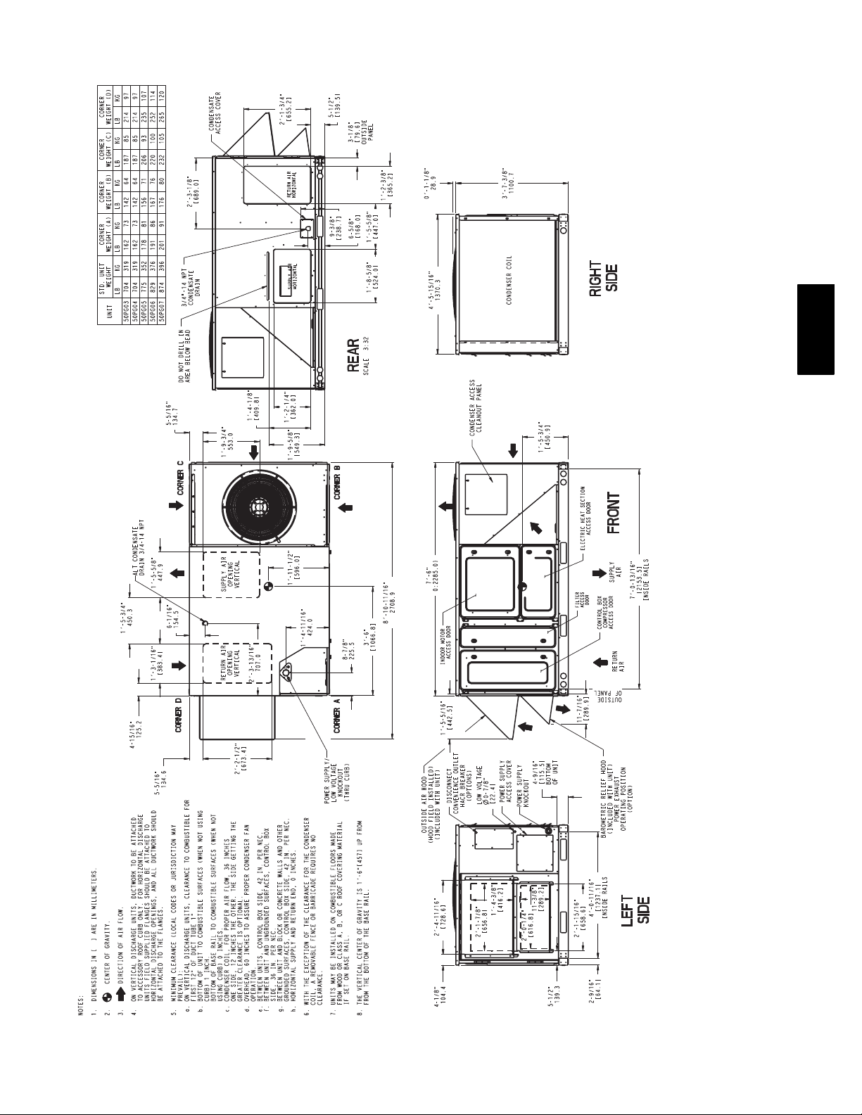
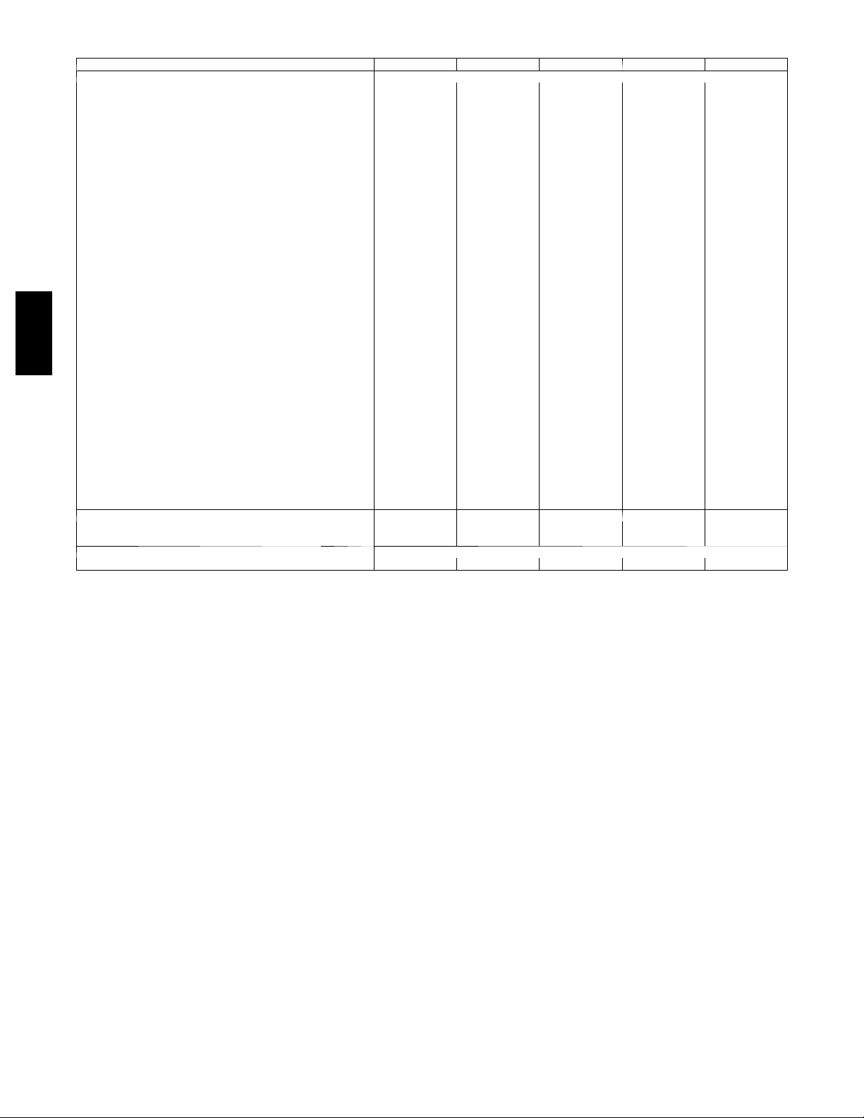
Table 1 – Physical Data
BASE UNIT 50PG 03 04 05 06 07
NOMINAL CAPACITY (Tons)
OPERATING WEIGHT (lb)
Unit*
Economizer
Vert ical
Horizontal
Humidi-MiZer™ Adaptive Dehumidification
System
Roof Curb
14-in.
24-in.
COMPRESSOR
Quantity
Oil Type
Number of Refrigerant Circuits
Oil (o z )
REFRIGERANT TYPE
Expansion Device
Operating Charge (lb) — Standard Unit
Operating Charge (lb) — Unit with
Humidi-MiZer System
CONDENSER COIL
Condenser A (Outer)
Rows...Fins/in.
Face A rea (s q ft)
Condenser B (Inner)
Rows...Fins/in.
Face A rea (s q ft)
Humidi-MiZer Coil
Rows...Fins/in.
Face A rea (s q ft)
CONDENSER FAN
Quantity…Diameter (in.)
Nominal Cfm (Total, all fans)
Motor Hp
Nominal Rpm — High Speed
Nominal Rpm — Low Speed
EVAPORATOR COIL
Rows…Fins/in.
Face A rea (s q ft)
* See Legend on next page.
2 3 4 5 6
704 704 775 829 874
40 40 40 40 40
50 50 50 50 50
22
22 31 27 26
122 122 122 122 122
184 184 184 184 184
Fully Hermetic Scroll
1 1 1 1 1
Copeland 3MA
1 1 1 1 1
38 42 42 66 56
R-410A (Puron® Refrigerant)
TXV TXV TXV TXV TXV
7.3 9.0 15.7 16.6 19.0
11.75 13.50 25.00 22.00 22.70
Enhanced Copper Tubes, Aluminum Lanced Fins
1…17 1…17 2…17 2…17 2…17
12.6 12.6 12.6 12.6 12.6
— 1…17 2…17 2…17 2…17
— 12.6 12.6 12.6 12.6
1...17 1...17 1...17 1...17 1...17
6.4 6.4 9.3 9.3 9.3
Propeller
1…24 1…24 1…24 1…24 1…24
3500 3500 3500 4500 4500
1
/
8
825 825 825 1100 1100
1
/
8
1
/
8
1
/
4
300 300 300 300 300
Enhanced Copper Tubes, Aluminum Double-Wavy Fins, Face Split
2…15 2…15 2…15 3…15 4…15
9.3 9.3 9.3 9.3 9.3
50PG03--07
1
/
4
5
BASE UNIT 50PG (co nt) 03 04 05 06 07
EVAPORATOR FAN
Quantity…Size (in.) Low
Ty pe D ri ve Low
Nominal Cfm
Maximum Continuous Bhp Low
Motor Nominal Rpm
Motor Frame Size Low
Fan Rp m Range Low
Motor Bearing Type
Maximum Fan Rpm
Motor Pulley Pitch Diameter Range (in.) Low
Fan Pulley Pitch Diameter (in.) Low
Nominal Motor Shaft Diameter (in.) Low
Belt...PitchLength(in.)
Belt…Ty pe Low
50PG03--07
Pulley Center L ine Distance Min. (in.) Low
Pulley Center Line Distance Max. (in.) Low
Speed Change per Full Turn of
Movable Pulley Flange (rpm)
Movable Pulley Maximum Full
Turns from Closed Position
FactoryPulleySetting(rpm) Low
Fan Shaft Diameter at Pulley (in.)
HIGH-PRESSURE SWITCH (psig)
Cutout
Reset (Auto.)
RETURN-AIR FILTERS
Quantity…Size (in.)
LEGEND
TXV --- Thermostatic Expansion Valve
* Aluminum evaporator coil/aluminum condenser coil.
{ Single phase/three phase.
Table 1 — Physical Data (cont)
High
High
High
High
High
High
High
High
Low
High
High
High
High
Low
High
Low
High
High
1...12 x 9
1...12 x 9
Belt
Belt
800 1200 1600 2000 2400
0.85
0.85
1620 1620 1620 1725 1725
48Y
48Y
482-736
656-1001
Ball Ball Ball Ball Ball
2000 2000 2000 2000 2000
1.9-2.9
1.9-2.9
6.8
5.0
1
/
2
1
/
2
49.3 49.3 49.3 49.3 49.3
49.3
AX
AX
16.2
16.2
20.2
20.2
48
65
5
5
482
656
3
/
4
660 ± 10 660 ± 10 660 ± 10 660 ± 10 660 ± 10
505 ± 20 505 ± 20 505 ± 20 505 ± 20 505 ± 20
4…16 x 20 x 2 4…16 x 20 x 2 4…16 x 20 x 2 4…16 x 20 x 2 4…16 x 20 x 2
1...12 x 9 1...12 x 9 1...12 x 9 1...12 x 9
Centrifugal Type, Belt Drive
1...12 x 9 1...12 x 9 1...12 x 9 1...12 x 9
Belt Belt Belt Belt
Belt Belt Belt Belt
0.85 0.85 0.85/2.40† 2.40
0.85 1.60/2.40† 1.60/2.40† 3.10
48Y 48Y 56Y 56Y
48Y 56Y 56Y 56Y
482-736 596-910 690-978 796-1128
796-1128 828-1173 929-1261 1150-1438
1.9-2.9 1.9-2.9 2.4-3.4 2.4-3.4
2.4-3.4 2.4-3.4 2.8-3.8 4.0-5.0
6.8 5.5 6.0 5.2
5.2 5.0 5.2 6.0
1
/
2
1
/
2
1
/
2
5
/
8
5
/
8
5
/
8
5
/
8
7
/
8
49.3 49.3 49.3 52.3
AX AX AX AX
AX AX AX AX
16.2 16.2 16.2 16.2
16.2 16.2 16.2 16.2
20.2 20.2 20.2 20.2
20.2 20.2 20.2 20.2
48 59 58 66
62 69 66 58
5 5 5 5
5 5 5 5
482 596 690 796
796 828 929 1150
3
/
4
3
/
4
3
/
4
3
/
4
Throwaway
6
Step 3 — Field Fabricate Ductwork
On vertical units, secure all ducts to roof curb and building
structure. Do not connect ductwork to unit. For horizontal
applications, field--supplied flanges should be attached to
horizontal discharge openings and all ductwork secured to the
flanges. Insulate and weatherproof all external ductwork, joints,
and roof openings with counter flashing and mastic in accordance
with applicable codes.
Ducts passing through an unconditioned space must be insulated
and covered with a vapor barrier.
If a plenum return is used on a vertical unit, the return should be
ducted through the roof deck to comply with applicable fire codes.
A minimum clearance is not required around ductwork. Cabinet
return--air static pressure (a negative condition) shall not exceed
0.35--in. wg with economizer or 0.45--in. wg without economizer.
Step 4 — Make Unit Duct Connections
Vertical Supply/Return Configuration
Unit is shipped in vertical supply/return configuration. Ductwork
openings are shown in Fig. 1 and 3. Attach the ductwork to the
roof curb. Do not attach duct directly to the unit.
!
WARNING
PERSONAL INJURY HAZARD
Failure to follow this warning could result in personal
injury.
For vertical supply and return units, tools or parts could
drop into ductwork and cause an injury. Install a
90--degree turn in the return ductwork between the unit
and the conditioned space. If a 90--degree elbow cannot
be installed, then a grille of sufficient strength and
density should be installed to prevent objects from
falling into the conditioned space.
Horizontal Supply/Return Applications
Unit can be field--converted from vertical supply/return to
horizontal supply/return. Remove all screws securing horizontal
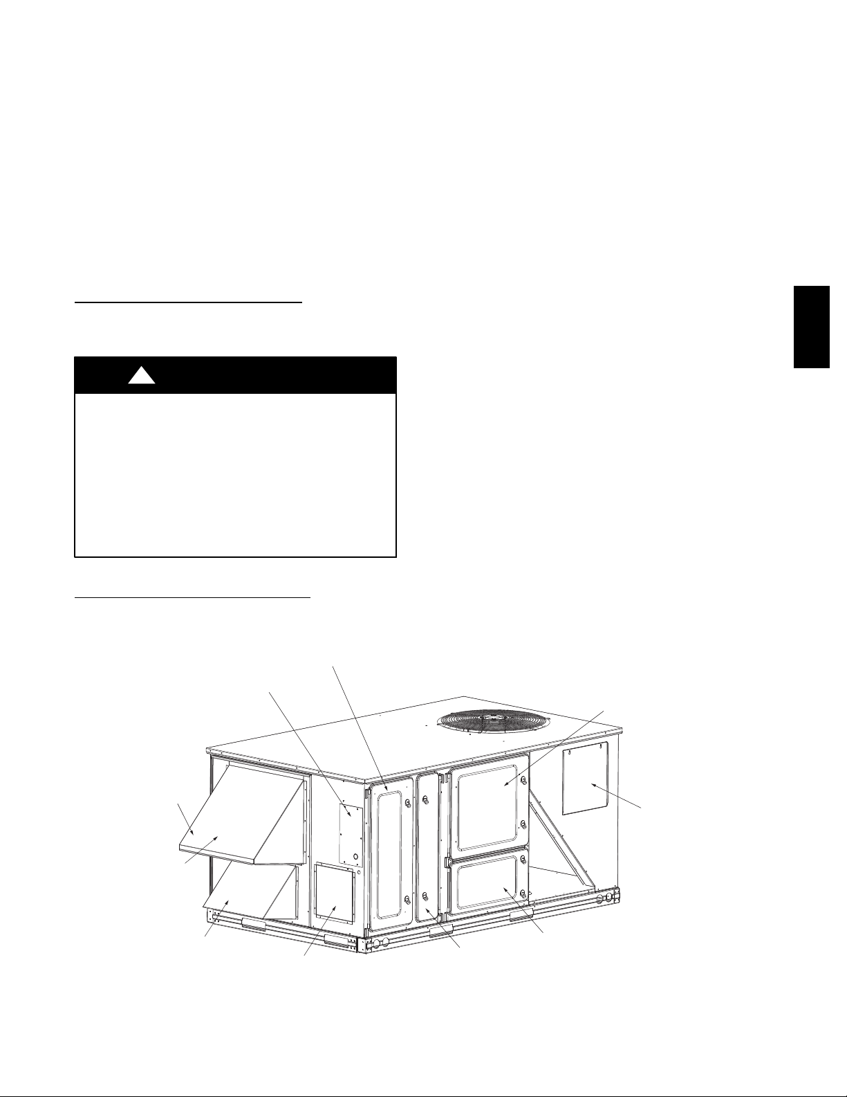
CONTROL BOX
AND
COMPRESSOR
ELECTRICAL
OPTIONS PANEL
duct covers to duct panel. Save panels. Install duct covers in the
vertical duct openings in the basepan with the insulation side up.
Covers will drop into openings and can be secured using
field--supplied self--tapping screws. Ductwork can be attached to
duct flanges provided on unit. When securing ductwork to unit, do
not drill in area below bead or above top edge of duct opening.
Step 5 — Install External Trap for Condensate
Drain
The unit’s 3/4--in. condensate drain connections are located on the
bottom and side of the unit. If the down drain is used, drill a
minimum of a 5/8-in. diameter hole but not larger than a
diameter hole through the drain pan. A dimple of 2 mm in
diameter and 1.5 mm deep will be provided in the drain pan to help
locate the drill bit and to start the hole. Do not cut through the
PVC pipe threads. Unit discharge connections do not determine
the use of drain connections; either drain connection can be used
with vertical or horizontal applications. See Fig. 2 for locations.
When using the standard side drain connection, make sure the plug
(red) in the alternate bottom connection is tight before installing the
unit. (See Fig. 5.)
To use the bottom drain connection for a roof curb installation,
relocate the factory--installed plug (red) from the bottom
connection to the side connection. A 1/2--in. socket extension can
be used to remove the plug. (See Fig. 5.) The piping for the
condensate drain and external trap can be completed after the unit
is in place.
All units must have an external trap for condensate drainage. Install
a trap at least 4--in. deep and protect against freezeup. If drain line
is installed downstream from the external trap, pitch the line away
from the unit at 1--in. per 10 ft of run. Do not use a pipe size
smaller than the unit connection (3/4--in.). (See Fig. 6 and 7.)
The 50PG units are provided with a removable condensate pan for
ease of cleaning. It is recommended that a union be placed between
the unit and condensate drainage to ease the removal of the pan
during servicing. Adequate clearance should be allowed if removal
of condensate pan is required. Allow 54--in. between condensate
pan access panel and any obstruction for complete removal.
INDOOR MOTOR
ACCESS DOOR
3
/4-in.
50PG03--07
OUTDOOR AIR
SCREEN
(HIDDEN)
ECONOMIZER
HOOD
BAROMETRIC
RELIEF DAMPER
HOOD
BASEPAN CONNECTIONS
ACCESS PANEL
Fig. 4 -- Panel and Filter Locations
FILTER ACCESS DOOR
7
ELECTRIC HEAT
ACCESS DOOR
CONDENSER COIL
ACCESS PANEL
C07272
 Loading...