


50HG014-028 Single Package Rooftop Units Electric Cooling with Electric Heat Option
Installation Instructions
CONTENTS
Page
SAFETY CONSIDERATIONS . . . . . . . . . . . . . . . . . . . . . . 1
INSTALLATION . . . . . . . . . . . . . . . . . . . . . . . . . . . . . . . . 1-23
Step 1 — Provide Unit Support . . . . . . . . . . . . . . . . . . . 1
•ROOF CURB
•ALTERNATE UNIT SUPPORT
Step 2 — Remove Shipping Rails . . . . . . . . . . . . . . . . 3
Step 3 — Rig and Place Unit . . . . . . . . . . . . . . . . . . . . . 3
•POSITIONING
•ROOF MOUNT
•INSTALLATION ONTO CURB
Step 4 — Field Fabricate Ductwork. . . . . . . . . . . . . . . 8 Step 5 — Make Unit Duct Connections . . . . . . . . . . . 8 Step 6 — Trap Condensate Drain . . . . . . . . . . . . . . . . . 9 Step 7 — Make Electrical Connections . . . . . . . . . . . 9
•FIELD POWER SUPPLY
•FIELD CONTROL WIRING
Step 8 — Install Outdoor-Air Hood . . . . . . . . . . . . . . 20
Step 9 — Position Optional Power Exhaust
or Barometric Relief Damper Hood. . . . . . . . . . . . 22 Step 10 — Non-Fused Disconnect. . . . . . . . . . . . . . . 22 Step 11 — Install All Accessories . . . . . . . . . . . . . . . 23
SAFETY CONSIDERATIONS
Installation and servicing of air-conditioning equipment can be hazardous due to system pressure and electrical components. Only trained and qualified service personnel should install, repair, or service air-conditioning equipment.
Untrained personnel can perform the basic maintenance functions of replacing filters. All other operations should be performed by trained service personnel. When working on air-conditioning equipment, observe precautions in the literature, tags and labels attached to the unit, and other safety precautions that may apply.
Follow all safety codes. Wear safety glasses and work gloves. Use quenching cloth for unbrazing operations. Have fire extinguishers available for all brazing operations.
Before performing service or maintenance operations on unit, turn off main power switch to unit. Electrical shock could cause personal injury.
IMPORTANT: Units have high ambient operating limits. If limits are exceeded, the units will automatically lock the compressor out of operation. Manual reset will be required to restart the compressor.
INSTALLATION
Step 1 — Provide Unit Support
ROOF CURB — Assemble or install accessory roof curb in accordance with instructions shipped with this accessory. See Fig. 1. Install insulation, cant strips, roofing, and counter flashing as shown. Ductwork can be installed to roof curb before unit is set in place. Curb must be level. This is necessary to permit unit drain to function properly. Unit leveling tolerance is
± 1/16 in. per linear ft in any direction. Refer to Accessory Roof Curb Installation Instructions for additional information as required. When accessory roof curb is used, unit may be installed on class A, B, or C roof covering material.
IMPORTANT: The gasketing of the unit to the roof curb is critical for a watertight seal. Install gasket with the roof curb as shown in Fig. 1. Improperly applied gasket can also result in air leaks and poor unit performance.
ALTERNATE UNIT SUPPORT — When a curb cannot be used, install unit on a noncombustible surface. Support unit with sleepers, using unit curb support area. If sleepers cannot be used, support long sides of unit with a minimum of 3 equally spaced 4-in. x 4-in. pads on each side.
Manufacturer reserves the right to discontinue, or change at any time, specifications or designs without notice and without incurring obligations.
Book |
1 |
4 |
PC 111 |
Catalog No. 535-00092 |
Printed in U.S.A. |
Form 50HG-7SI |
Pg 1 |
11-03 |
Replaces: 50HG-3SI |
Tab |
1b |
6b |
|
|
|
|
|
|
|
|
|
|
|
|
|
|
|
|
|
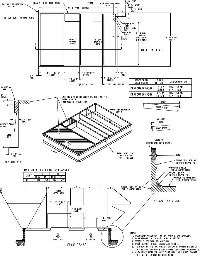
Fig. 1 — Roof Curb Details
2
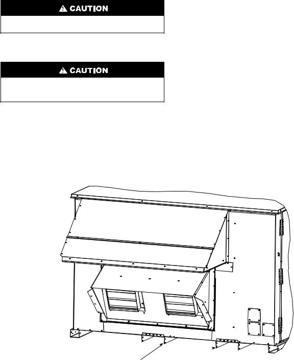
Step 2 — Remove Shipping Rails — Remove shipping rails prior to lowering unit onto roof curb. See Fig. 2. The rails are attached to the unit at both the return end and condenser end. Remove the screws from both ends of each rail. Be careful not to drop the rails onto any surface that could be damaged. Discard the rails. It is important to replace the screws into the unit to avoid any air or water leakage.
Do not allow the shipping rail to drop on the roof surface. Damage to the roof surface may result.
Step 3 — Rig and Place Unit — Inspect unit for transportation damage. See Table 1 for physical data. File any claim with transportation agency.
All panels must be in place when rigging. Unit is not designed for handling by fork truck. Damage to unit can result.
Do not drop unit; keep upright. Use spreader bars over unit to prevent sling or cable damage. Rollers may be used to move unit across a roof. Level by using unit frame as a reference; leveling tolerance is ± 1/16 in. per linear ft in any direction. See Fig. 3 for additional information. Unit rigging weight is shown in Fig. 3.
Four lifting holes are provided in the unit base rails as shown in Fig. 3. Refer to rigging instructions on unit.
POSITIONING — Maintain clearance, per Fig. 4, around and above unit to provide minimum distance from combustible materials, proper airflow, and service access.
Do not install unit in an indoor location. Do not locate air inlets near exhaust vents or other sources of contaminated air.
Although unit is weatherproof, guard against water from higher level runoff and overhangs.
ROOF MOUNT — Check building codes for weight distribution requirements. Unit operating weight is shown in Table 1.
INSTALLATION ONTO CURB — The 50HG units are designed to fit on either the accessory full perimeter curb or onto existing 48/50TJ,HJ or 48/50DP,DR curbs. In either case, correct placement of the unit onto the curb is critical to operating performance. To aid in correct positioning, 3/8-in. diameter locating holes have been added to the unit base rails. When placing the unit, these holes should line up with the roof curb edge as shown in Fig. 5 and 6, to assure proper duct opening alignment. Select the alignment holes suited for the curb being used. For installation on the HJ/TJ/DP/DR curb use the alignment holes located approximately 20 in. from the end of the base rail on the return end of the unit. For placement on the HG curb, use the alignment holes located approximately 2-in. from the end of the base rail on the return end of the unit. See labels on the side of the unit for more details.
SHIPPING RAILS 
Fig. 2 — Shipping Rail Removal
3
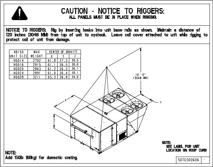
Fig. 3 — Rigging Details
4

Fig. 4 — Base Unit Dimensions
5
Table 1 — Physical Data
UNIT 50HG |
|
|
|
|
|
014 |
|
|
|
|
|
|
016 |
|
|
|
|
|
|
020 |
|
|
||||
VOLTAGE |
|
|
208/230 |
|
575 |
|
208/230 |
|
575 |
|
|
208/230 |
|
|
575 |
|
||||||||||
|
|
and 460 |
|
|
and 460 |
|
|
|
and 460 |
|
|
|
||||||||||||||
|
|
|
|
|
|
|
|
|
|
|
|
|
|
|
|
|||||||||||
NOMINAL CAPACITY (Tons) |
|
|
12.5 |
|
12.5 |
|
|
15 |
|
|
|
15 |
|
|
|
17.5 |
|
|
|
17.5 |
|
|||||
OPERATING WEIGHT (lb) |
|
|
|
|
|
|
|
|
|
|
|
|
|
|
|
|
|
|
|
|
|
|
|
|
|
|
50 SERIES (Cooling Only) |
|
|
2017 |
|
2017 |
|
2111 |
|
2111 |
|
2139 |
|
|
2139 |
|
|||||||||||
COMPRESSOR |
|
|
|
|
|
|
|
|
|
|
|
|
|
|
|
|
|
|
|
|
|
|
|
|
|
|
Quantity |
|
|
|
|
2 |
|
|
|
2 |
|
|
|
3 |
|
|
|
3 |
|
|
|
3 |
|
|
|
3 |
|
Number of Refrigerant Circuits |
|
|
|
2 |
|
|
|
2 |
|
|
|
3 |
|
|
|
3 |
|
|
|
3 |
|
|
|
3 |
|
|
Oil (ounces) Ckt A...Ckt B...Ckt C |
|
72... |
|
72... |
NA |
72... |
|
72... |
NA |
68... |
68... |
68 |
68... |
|
68... |
68 |
|
68... |
68... |
72 |
|
68... |
68... |
72 |
||
REFRIGERANT TYPE |
|
|
|
|
|
|
|
|
|
|
|
|
R-22 |
|
|
|
|
|
|
|
|
|
|
|
||
Expansion Device |
|
|
TXV |
|
TXV |
|
TXV |
|
TXV |
|
|
TXV |
|
|
|
TXV |
|
|||||||||
|
|
|
|
|
|
|
|
|
|
|
||||||||||||||||
Operating Charge (lb) |
|
|
|
|
|
|
|
|
|
|
|
|
|
|
|
|
|
|
|
|
|
|
|
|
|
|
Circuit A |
|
|
19.6 |
|
19.6 |
|
13.2 |
|
13.2 |
|
|
13.1 |
|
|
|
13.1 |
|
|||||||||
Circuit B |
|
|
18.3 |
|
18.3 |
|
12.2 |
|
12.2 |
|
|
12.7 |
|
|
|
12.7 |
|
|||||||||
Circuit C |
|
|
|
NA |
|
|
|
NA |
|
|
15.4 |
|
15.4 |
|
|
15.2 |
|
|
|
15.2 |
|
|||||
CONDENSER COIL |
|
|
|
|
|
|
|
|
|
|
|
|
|
|
|
|
|
|
|
|
|
|
|
|
|
|
Rows...Fins/inch |
|
|
2 |
...17 |
|
2 |
...17 |
|
2... |
17 |
|
2 |
...17 |
|
2 17... |
|
2 17... |
|
||||||||
Total Face area (sq. ft) |
|
|
57.78 |
|
57.78 |
|
57.78 |
|
57.78 |
|
57.78 |
|
57.78 |
|
||||||||||||
CONDENSER FAN |
|
|
|
|
|
|
|
|
|
|
|
|
|
|
|
|
|
|
|
|
|
|
|
|
|
|
Nominal Cfm (Total, all fans) |
|
14,000 |
14,000 |
|
14,000 |
14,000 |
|
14,000 |
|
14,000 |
||||||||||||||||
Quantity... |
Diameter (in.) |
|
|
4 |
...22 |
|
4 |
...22 |
|
4... |
22 |
|
4 |
...22 |
|
4 22... |
|
4 22... |
|
|||||||
Motor Hp... |
Rpm |
|
1/4... |
1100 |
1/4... |
1100 |
1/4... |
1100 |
1/4... |
1100 |
|
1/4 |
...1100 |
|
1/4 |
...1100 |
||||||||||
Watts input (Total) |
|
|
1400 |
|
1400 |
|
1400 |
|
1400 |
|
1400 |
|
|
1400 |
|
|||||||||||
EVAPORATOR COIL |
|
|
|
|
|
|
|
|
|
|
|
Face |
Split |
|
|
|
|
|
|
|
|
|
|
|
||
Rows Fins/inch |
|
|
3 |
15 |
|
3 |
15 |
|
3 |
15 |
|
3 |
15 |
|
3 15 |
|
3 15 |
|
||||||||
|
|
|
|
|
|
|
|
|||||||||||||||||||
Total Face area (sq. ft) |
|
|
23.33 |
|
23.33 |
|
23.33 |
|
23.33 |
|
23.33 |
|
23.33 |
|
||||||||||||
EVAPORATOR FAN |
|
|
|
|
|
|
|
|
|
|
|
|
|
|
|
|
|
|
|
|
|
|
|
|
|
|
Quantity... |
Size |
|
2... |
|
15x11 |
2... |
|
15x11 |
2... |
15x11 |
2... |
|
15x11 |
|
2... |
15x11 |
|
2... |
15x11 |
|||||||
Type Drive |
|
|
Belt |
|
|
Belt |
|
|
Belt |
|
|
Belt |
|
|
|
Belt |
|
|
|
Belt |
|
|||||
Nominal Cfm |
|
|
5000 |
|
5000 |
|
6000 |
|
6000 |
|
7000 |
|
|
7000 |
|
|||||||||||
Std Motor Hp |
|
|
|
3.7 |
|
|
|
3 |
|
|
|
3.7 |
|
|
|
3 |
|
|
|
5 |
|
|
|
5 |
|
|
Alt Motor Hp |
|
|
|
5 |
|
|
|
5 |
|
|
|
5 |
|
|
|
5 |
|
|
|
71/2 |
|
|
|
71/2 |
|
|
Motor Nominal Rpm |
|
|
1725 |
|
1725 |
|
1725 |
|
1725 |
|
1725 |
|
|
1725 |
|
|||||||||||
Std Maximum Continuous Bhp |
|
|
4.25 |
|
3.45 |
|
4.25 |
|
3.45 |
|
|
5.75 |
|
|
|
5.75 |
|
|||||||||
Std Maximum Continuous Watts |
|
|
3171 |
|
2574 |
|
3171 |
|
2574 |
|
4290 |
|
|
4290 |
|
|||||||||||
Alt Maximum Continuous Bhp |
|
|
5.75 |
|
5.75 |
|
5.75 |
|
5.75 |
|
|
8.63 |
|
|
|
8.63 |
|
|||||||||
Alt Maximum Continuous Watts |
|
|
4290 |
|
4290 |
|
4290 |
|
4290 |
|
6438 |
|
|
6438 |
|
|||||||||||
Motor Frame Size |
Standard |
|
56HZ |
|
56H |
|
56HZ |
|
56H |
|
S184T |
|
184T |
|
||||||||||||
Motor Frame Size |
Alternate |
S184T |
|
184T |
|
S184T |
|
184T |
|
S213T |
|
S213T |
||||||||||||||
Fan Drive Rpm Range |
Std motor/Std drive |
485-613 |
472-619 |
618-789 |
609-778 |
|
658-808 |
|
658-808 |
|||||||||||||||||
|
|
Std motor/Alt drive |
618-789 |
609-778 |
485-613 |
472-619 |
|
794-974 |
|
794-974 |
||||||||||||||||
|
|
Alt motor/Std drive |
778-1021 |
778-1021 |
778-1021 |
778-1021 |
|
949-1145 |
|
949-1145 |
||||||||||||||||
Motor Bearing Type |
Alt motor/Alt drive |
1000-1227 |
1000-1227 |
1000-1227 |
1000-1227 |
|
1126-1328 |
|
1126-1328 |
|||||||||||||||||
|
|
Ball |
|
|
Ball |
|
|
Ball |
|
|
Ball |
|
|
|
Ball |
|
|
|
Ball |
|
||||||
Maximum Allowable Rpm |
|
|
1400 |
|
1400 |
|
1400 |
|
1400 |
|
1400 |
|
|
1400 |
|
|||||||||||
Motor Pulley Pitch Diameter |
Std motor/Std drive |
3.7-4.7 |
3.1-4.1 |
|
3.4-4.4 |
3.4-4.4 |
|
4.3-5.3 |
|
4.3-5.3 |
||||||||||||||||
|
|
Std motor/Alt drive |
3.4-4.4 |
3.4-4.4 |
|
3.7-4.7 |
3.1-4.1 |
|
4.3-5.3 |
|
4.3-5.3 |
|||||||||||||||
|
|
Alt motor/Std drive |
3.1-4.1 |
3.1-4.1 |
|
3.1-4.1 |
3.1-4.1 |
|
5.4-6.6 |
|
5.4-6.6 |
|||||||||||||||
|
|
Alt motor/Alt drive |
4.3-5.3 |
4.3-5.3 |
|
4.3-5.3 |
4.3-5.3 |
|
5.5-6.5 |
|
5.5-6.5 |
|||||||||||||||
Motor Shaft Diameter (in.) |
Standard |
|
|
7/8 |
|
|
|
7/8 |
|
|
|
7/8 |
|
|
|
7 /8 |
|
|
|
11/8 |
|
|
|
11/8 |
|
|
Motor Shaft Diameter (in.) |
Alternate |
1 |
11/8 |
51 |
1 |
11/8 |
48 |
|
11/8 |
45 |
1 |
11/8 |
45 |
|
1 |
13/8 |
46 |
|
1 |
13/8 |
46 |
|||||
Belt, Quantity...Type...Length (in.) |
Std motor/Std drive |
BX... |
BX... |
1... |
A... |
... |
A |
|
BX... |
|
BX... |
|||||||||||||||
|
|
Std motor/Alt drive |
1... |
|
A... |
45 |
1... |
|
A... |
45 |
1... |
BX... |
51 |
1... |
BX... |
48 |
|
1... |
BX... |
42 |
|
1... |
BX... |
42 |
||
|
|
Alt motor/Std drive |
1... |
BX... |
38 |
1... |
BX... |
38 |
1... |
BX... |
38 |
1... |
BX... |
38 |
|
1... |
BX... |
46 |
|
1... |
BX... |
46 |
||||
Pulley center line distance (in.) |
Alt motor/Alt drive |
1... |
|
B... |
38 |
1... |
|
B... |
38 |
1... |
B... |
38 |
1... |
... |
B |
38 |
|
1... |
BX... |
42 |
|
1... |
BX... |
42 |
||
|
11.3-12.3 |
11.3-12.3 |
11.3-12.3 |
11.3-12.3 |
|
10.0-12.2 |
|
10.0-12.2 |
||||||||||||||||||
Speed change per full turn of moveable |
|
|
|
|
|
|
|
|
|
|
|
|
|
|
|
|
|
|
|
|
|
|
|
|
|
|
pulley flange (rpm) |
Std motor/Std drive |
|
|
21 |
|
|
|
25 |
|
|
|
29 |
|
|
|
28 |
|
|
|
25 |
|
|
|
25 |
|
|
|
|
Std motor/Alt drive |
|
|
29 |
|
|
|
28 |
|
|
|
21 |
|
|
|
25 |
|
|
|
30 |
|
|
|
30 |
|
|
|
Alt motor/Std drive |
|
|
41 |
|
|
|
41 |
|
|
|
41 |
|
|
|
41 |
|
|
|
33 |
|
|
|
33 |
|
Moveable pulley maximum (full turns |
Alt motor/Alt drive |
|
|
38 |
|
|
|
38 |
|
|
|
38 |
|
|
|
38 |
|
|
|
34 |
|
|
|
34 |
|
|
|
|
|
6 |
|
|
|
6 |
|
|
|
6 |
|
|
|
6 |
|
|
|
6 |
|
|
|
6 |
|
||
from closed position) |
|
|
|
|
|
|
|
|
|
|
|
|
|
|
|
|
|
|
|
|
|
|
|
|
|
|
Factory Pulley Setting |
|
|
|
|
|
|
|
|
|
|
|
|
|
|
|
|
|
|
|
|
|
|
|
|
|
|
(turns from closed position) |
|
|
|
3 |
|
|
|
3 |
|
|
|
3 |
|
|
|
3 |
|
|
|
3 |
|
|
|
3 |
|
|
Fan Shaft Diameter (in.) |
|
|
13/16 |
|
13/16 |
|
13/16 |
|
13/16 |
|
|
13/16 |
|
|
|
13/16 |
|
|||||||||
Factory Speed Setting (rpm) |
|
|
549 |
|
|
546 |
|
|
704 |
|
|
694 |
|
|
|
733 |
|
|
|
733 |
|
|||||
HIGH PRESSURE SWITCHES (psig) |
|
|
|
|
|
|
|
|
|
|
|
|
|
|
|
|
|
|
|
|
|
|
|
|
|
|
Cutout |
|
|
|
426 |
|
|
426 |
|
|
426 |
|
|
426 |
|
|
|
426 |
|
|
|
426 |
|
||||
Reset (Auto) |
|
|
320 |
|
|
320 |
|
|
320 |
|
|
320 |
|
|
|
320 |
|
|
|
320 |
|
|||||
OUTDOOR AIR INLET SCREENS |
|
|
|
|
|
|
|
|
|
|
|
|
|
|
|
|
|
|
|
|
|
|
|
|
|
|
Quantity... |
Size (in.) |
|
3... |
|
20x25 |
3... |
|
20x25 |
3... |
20x25 |
3... |
|
20x25 |
|
3... |
20x25 |
|
3... |
20x25 |
|||||||
RETURN AIR FILTERS |
|
|
|
|
|
|
|
|
|
|
|
|
|
|
|
|
|
|
|
|
|
|
|
|
|
|
Quantity... |
Size (in.) |
|
9... |
|
16x25 |
9... |
|
16x25 |
9... |
16x25 |
9... |
|
16x25 |
|
9... |
16x25 |
|
9... |
16x25 |
|||||||
LEGEND
Bhp — Brake Horsepower
TXV — Thermostatic Expansion Valve
6
Table 1 — Physical Data (cont)
UNIT 50HG |
|
|
024 |
|
028 |
||
VOLTAGE |
|
208/230 |
|
|
575 |
|
ALL |
|
and 460 |
|
|
|
|||
|
|
|
|
|
|
|
|
NOMINAL CAPACITY (Tons) |
|
20 |
|
|
20 |
|
25 |
OPERATING WEIGHT (lb) |
|
|
|
|
|
|
|
50 SERIES (Cooling Only) |
|
2187 |
|
|
2187 |
|
2446 |
COMPRESSOR |
|
|
|
|
|
|
|
Quantity |
|
3 |
|
|
3 |
|
2 |
Number of Refrigerant Circuits |
|
3 |
|
|
3 |
|
2 |
Oil (ounces) Ckt A...Ckt B...Ckt C |
|
72...72...72 |
|
|
72...72...72 |
|
110...110...NA |
REFRIGERANT TYPE |
|
|
|
|
R-22 |
|
|
Expansion Device |
|
TXV |
|
|
TXV |
|
TXV |
|
|
|
|
||||
Operating Charge (lb) |
|
|
|
|
|
|
|
Circuit A |
|
13.8 |
|
|
13.8 |
|
23.9 |
Circuit B |
|
13.9 |
|
|
13.9 |
|
21.5 |
Circuit C |
|
15.5 |
|
|
15.5 |
|
NA |
CONDENSER COIL |
|
|
|
|
|
|
|
Rows...Fins/inch |
|
2...17 |
|
|
2...17 |
|
2...17 |
Total Face Area (sq. ft) |
|
57.78 |
|
|
57.78 |
|
66.67 |
CONDENSER FAN |
|
|
|
|
|
|
|
Nominal Cfm (Total, all fans) |
|
14,000 |
|
|
14,000 |
|
21,000 |
Quantity...Diameter (in.) |
|
4...22 |
|
|
4...22 |
|
6...22 |
Motor Hp...Rpm |
|
1/4...1100 |
|
|
1/4...1100 |
|
1/4...1100 |
Watts input (Total) |
|
1400 |
|
|
1400 |
|
2100 |
EVAPORATOR COIL |
|
|
|
|
Face Split |
|
|
Rows...Fins/inch |
|
4...15 |
|
|
4...15 |
|
4...15 |
|
|
|
|||||
Total Face Area (sq. ft) |
|
23.33 |
|
|
23.33 |
|
27.22 |
EVAPORATOR FAN |
|
|
|
|
|
|
|
Quantity...Size |
|
2...15x11 |
|
|
2...15x11 |
|
2...15x11 |
Type Drive |
|
Belt |
|
|
Belt |
|
Belt |
Nominal Cfm |
|
8000 |
|
|
8000 |
|
10,000 |
Std Motor Hp |
|
5 |
|
|
5 |
|
71/2 |
Alt Motor Hp |
|
71/2 |
|
|
71/2 |
|
10 |
Motor Nominal Rpm |
|
1725 |
|
|
1725 |
|
1725 |
Std Maximum Continuous Bhp |
|
5.75 |
|
|
5.75 |
|
8.63 |
Std Maximum Continuous Watts |
|
4290 |
|
|
4290 |
|
6438 |
Alt Maximum Continuous Bhp |
|
8.63 |
|
|
8.63 |
|
11.50 |
Alt Maximum Continuous Watts |
|
6438 |
|
|
6438 |
|
8579 |
Motor Frame Size |
Standard |
S184T |
|
|
184T |
|
S213T |
Motor Frame Size |
Alternate |
S213T |
|
|
S213T |
|
S215T |
Fan Drive Rpm Range |
Std motor/Std drive |
658-808 |
|
|
658-808 |
|
799-965 |
|
Std motor/Alt drive |
794-974 |
|
|
794-974 |
|
939-1152 |
|
Alt motor/Std drive |
949-1145 |
|
|
949-1145 |
|
945-1187 |
Motor Bearing Type |
Alt motor/Alt drive |
1126-1328 |
|
|
1126-1328 |
|
1152-1366 |
|
Ball |
|
|
Ball |
|
Ball |
|
Maximum Allowable Rpm |
|
1400 |
|
|
1400 |
|
1400 |
Motor Pulley Pitch Diameter |
Std motor/Std drive |
4.3-5.3 |
|
|
4.3-5.3 |
|
5.4-6.6 |
|
Std motor/Alt drive |
4.3-5.3 |
|
|
4.3-5.3 |
|
4.2-5.2 |
|
Alt motor/Std drive |
5.4-6.6 |
|
|
5.4-6.6 |
|
4.2-5.2 |
|
Alt motor/Alt drive |
5.5-6.5 |
|
|
5.5-6.5 |
|
5.2-6.2 |
Motor Shaft Diameter (in.) |
Standard |
11/8 |
|
|
11/8 |
|
13/8 |
Motor Shaft Diameter (in.) |
Alternate |
13/8 |
|
|
13/8 |
|
13/8 |
Belt, Quantity...Type...Length (in.) |
Std motor/Std drive |
1...BX...46 |
|
|
1...BX...46 |
|
1...BX...50 |
|
Std motor/Alt drive |
1...BX...42 |
|
|
1...BX...42 |
|
2...AX...38 |
|
Alt motor/Std drive |
1...BX...46 |
|
|
1...BX...46 |
|
2...BX...38 |
Pulley center line distance (in.) |
Alt motor/Alt drive |
1...BX...42 |
|
|
1...BX...42 |
|
2...BX...38 |
|
10.0-12.2 |
|
|
10.0-12.2 |
|
9.6-12.0 |
|
Speed change per full turn of moveable |
|
|
|
|
|
|
|
pulley flange (rpm) |
Std motor/Std drive |
25 |
|
|
25 |
|
28 |
|
Std motor/Alt drive |
30 |
|
|
30 |
|
36 |
|
Alt motor/Std drive |
33 |
|
|
33 |
|
40 |
Moveable pulley maximum (full turns |
Alt motor/Alt drive |
34 |
|
|
34 |
|
36 |
|
6 |
|
|
6 |
|
6 |
|
from closed position) |
|
|
|
|
|
|
|
Factory Pulley Setting |
|
|
|
|
|
|
|
(turns from closed position) |
|
3 |
|
|
3 |
|
3 |
Fan Shaft Diameter (in.) |
|
13/16 |
|
|
13/16 |
|
13/16 |
Factory Speed Setting (rpm) |
|
733 |
|
|
733 |
|
882 |
HIGH PRESSURE SWITCHES (psig) |
|
|
|
|
|
|
|
Cutout |
|
426 |
|
|
426 |
|
426 |
Reset (Auto) |
|
320 |
|
|
320 |
|
320 |
OUTDOOR AIR INLET SCREENS |
|
|
|
|
|
|
|
Quantity...Size (in.) |
|
3...20x25 |
|
|
3...20x25 |
|
3...20x25 |
RETURN AIR FILTERS |
|
|
|
|
|
|
|
Quantity...Size (in.) |
|
9...16x25 |
|
|
9...16x25 |
|
9...20x25 |
LEGEND
Bhp — Brake Horsepower
TXV — Thermostatic Expansion Valve
7
ALIGNMENT
HOLE
(IN BASE RAIL)
ALIGNMENT
HOLE SHOULD
LINE UP WITH
ROOF CURB
EDGE FLANGE
EDGE FLANGE
Fig. 5 — Alignment Hole Details
ALIGNMENT
HOLES FOR
HJ, TJ, DP, DR
CURB-BOTH
SIDES
|
RETURN |
SUPPLY |
|
OPENING |
OPENING |
|
CURB |
CURB |
|
RETURN |
SUPPLY |
ALIGNMENT |
OPENING |
OPENING |
|
|
|
HOLES FOR HG |
|
|
CURB-BOTH |
|
|
SIDES |
ROOF CURB |
|
Fig. 6 — Alignment Hole Location
Step 4 — Field Fabricate Ductwork — Secure all ducts to building structure. Use flexible duct connectors between unit and ducts as required. Insulate and weatherproof all external ductwork, joints, and roof openings with counter flashing and mastic in accordance with applicable codes.
Ducts passing through an unconditioned space must be insulated and covered with a vapor barrier.
Step 5 — Make Unit Duct Connections
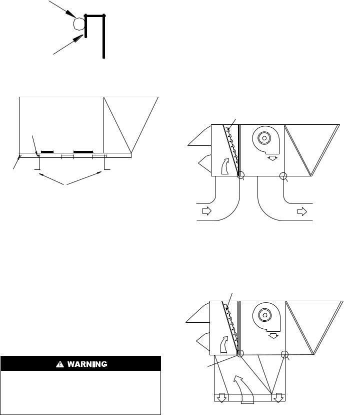
VERTICAL CONFIGURATION — Unit is shipped for thru- the-bottom duct connections. Ductwork openings are shown in Fig. 1 and 4. Duct connections for vertical supply and return configuration are shown in Fig. 7. Field fabricated concentric ductwork may be connected as shown in Fig. 8 and 9. The unit is designed to attach the ductwork to the roof curb. Do not attach duct directly to the unit basepans.
Unit basepans must be supported under the unit and around duct openings in order to prevent air leakage.
For vertical supply and return units, tools or parts could drop into ductwork and cause an injury. Install a 90-degree turn in the return ductwork between the unit and the conditioned space. If a 90-degree elbow cannot be installed, then a grille of sufficient strength and density should be installed to prevent objects from falling into the conditioned space.
Units with electric heat require a 1-in. clearance for the first 24 in. of ductwork. Outlet grilles must not lie directly below unit discharge.
NOTE: A 90-degree elbow must be provided in the supply ductwork to comply with UL (Underwriters’ Laboratories) codes for use with electric heat.
HORIZONTAL APPLICATIONS — Horizontal units are shipped with outer panels that allow for side by side horizontal duct connections. If specified during ordering, the unit will be shipped with the vertical duct openings blocked off from the factory, ready for side supply installation. If the horizontal option was not specified at time of ordering the unit, a fieldinstalled accessory kit is required to convert the vertical unit into a horizontal supply configuration.
Installation of the duct block-off covers should be completed prior to placing the unit unless sufficient side clearance is available. A minimum of 66-in. is required between the unit and any obstruction to install the duct block-off covers. Side supply duct dimensions and locations are shown on Fig. 4. Connect ductwork to horizontal duct flange connections on side of unit.
ECONOMIZER
|
SEE |
SEE |
|
NOTE |
|
|
NOTE |
|
|
|
|
AIR |
|
AIR |
IN |
|
OUT |
NOTE: Do not drill in this area; damage to basepan may result in water leak.
Fig. 7 — Air Distribution —
Vertical Supply and Return
ECONOMIZER
SEE |
|
SEE |
NOTE |
|
NOTE |
AIR OUT |
AIR IN |
AIR OUT |
NOTE: Do not drill in this area; damage to basepan may result in water leak.
Fig. 8 — Air Distribution — Concentric Duct
8
 Loading...