


48GP (N) 024-060, 48JZ (N) 024-060 50GL 024-060, 50JZ 024-060 ICM FIOP Installation Instructions
Visit www.carrier.com
Installation, Start-Up, and Operating Instructions
NOTE: Read the entire instruction manual before starting the installation.
TABLE OF CONTENTS |
|
SAFETY CONSIDERATIONS ..................................................... |
1 |
INTRODUCTION .......................................................................... |
2 |
RECEIVING AND INSTALLATION .......................................... |
2 |
ICM FIOP PRE-START-UP.......................................................... |
2 |
Electrical Connections .............................................................. |
2 |
Control Voltage Connections .............................................. |
2 |
Standard Connection............................................................ |
2 |
Easy Select™—48GP.......................................................... |
2 |
48GP Sequence of Operation.............................................. |
4 |
Easy Select™—48JZ........................................................... |
5 |
48JZ Sequence of Operation............................................... |
7 |
Easy Select™—50GL & 50JZ............................................ |
7 |
50GL & 50JZ Sequence Of Operation............................... |
9 |
ICM FIOP START-UP ................................................................ |
10 |
48GP Start-Up (ICM FIOP) ................................................... |
10 |
48JZ Start-Up (ICM FIOP) .................................................... |
10 |
50GL: Start-Up (ICM FIOP).................................................. |
11 |
50JZ: Start-Up (ICM FIOP) ................................................... |
11 |
ELECTRICAL DATA & SCHEMATICS—ICM FIOP............. |
12 |
Physical Data & Electrical Schematics.................................. |
12 |
Tables For System Set-Up...................................................... |
12 |
CARE AND MAINTENANCE................................................... |
12 |
TROUBLESHOOTING ............................................................... |
13 |
START-UP CHECKLIST............................................................ |
13 |
NOTE TO INSTALLER — READ THESE INSTRUCTIONS CAREFULLY AND COMPLETELY before installing this unit. Also, make sure the Owner’s Manual and Service Instructions are left with the unit after installation.
SAFETY CONSIDERATIONS
Installation and servicing of air-conditioning equipment can be hazardous due to system pressure and electrical components. Only trained and qualified personnel should install, repair, or service air-conditioning equipment.
Untrained personnel can perform basic maintenance functions of cleaning coils and filters. All other operations should be performed by trained service personnel. When working on air-conditioning equipment, observe precautions in the literature, tags, and labels attached to the unit, and other safety precautions that may apply.
Follow all safety codes. Wear safety glasses and work gloves. Use quenching cloth for unbrazing operations. Have fire extinguisher available for all brazing operations.
C99088
Fig. 1—Puron® Unit (48GP Shown)
Improper installation, adjustment, alteration, service, maintenance, or use can cause explosion, fire, electric shock, or other occurrences, which could cause serious injury or death or damage your property. Consult a qualified installer or service agency for information or assistance. The qualified installer or agency must use only factory-authorized kits or accessories when modifying this product.
Recognize safety information. This is the safety-alert symbol . When you see this symbol on the product or in instructions or manuals, be alert to the potential for personal injury.
Understand the signal words — DANGER, WARNING, CAUTION, and NOTE. Danger identifies the most serious hazards, which will result in severe personal injury or death. Warning indicates a condition that could cause serious personal injury or death. Caution is used to identify unsafe practices, which would result in minor personal injury or product and property damage. NOTE is used to highlight suggestions which will result in enhanced installation, reliability, or operation.
The power supply (volts, phase, and hertz) must correspond to that specified on unit rating plate.
The electrical supply provided by the utility must be sufficient to handle load imposed by this unit. Electrical supply must match the voltage requirements listed on unit rating plate.
This installation must conform with local building codes and with NEC (National Electrical Code). Refer to provincial and local plumbing or waste water codes and other applicable local codes.
Manufacturer reserves the right to discontinue, or change at any time, specifications or designs without notice and without incurring obligations.
Book |
1 |
4 |
PC 101 |
Catalog No. 534-80085 |
Printed in U.S.A. |
Form 48–21SI |
Pg 1 |
10-01 |
Replaces: 48–20SI |
Tab |
1a |
1a |
|
|
|
|
|
|
|
Approved for outdoor installation on wood flooring or on class A, B or C roof covering materials.
Before performing service or maintenance operations on system, turn off main power to unit and install lock-out tag. Turn off accessory heater power switch if applicable. Electrical shock could cause severe injury or death.
Puron® (R-410A) systems operate at higher pressures than standard R-22 systems. Do not use R-22 service equipment or components on Puron® (R-410A) equipment. Ensure service equipment is rated for Puron® (R-410A)
INTRODUCTION
NOTE: The minimum outdoor cooling operating temperature for units using this ICM motor option is 55°F. To operate in cooling at lower ambients the Motor Master™ II low ambient kit is required.
These instructions cover the installation of a Carrier Small Packaged Product with ICM motor-factory installed option (FIOP). This option can be selected as a FIOP on gas heating/electric cooling (48GP), dual fuel–electric heat pump with gas heat back-up (48JZ), electric cooling (50GL) or electric heat pump (50JZ) units with Puron®.
RECEIVING AND INSTALLATION
Refer to unit Installation Instructions.
ICM FIOP PRE-START-UP
Step 1—Electrical Connections
CONTROL VOLTAGE CONNECTIONS
NOTE: Do not use any type of power-stealing thermostat, without connecting the C (Common) terminal. Failure to follow this note could result in unit control problems.
Use no. 18 American Wire Gage (AWG) color-coded, insulated (35 C minimum) wires to make the control voltage connections between the thermostat and the unit. If the thermostat is located more than 100 ft from the unit (as measured along the control voltage wires), use no. 16 AWG color-coded, insulated (35 C minimum) wires.
STANDARD CONNECTION
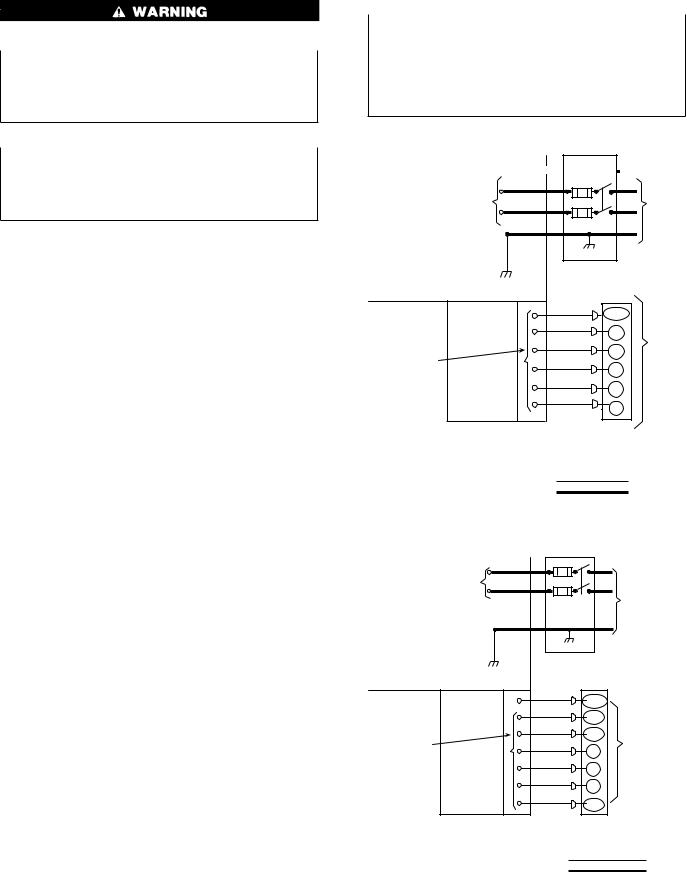
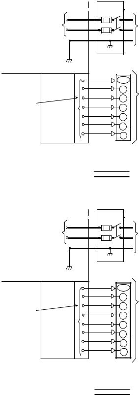
Remove knockout hole located in the heat section panel adjacent to the service access panel (See unit installation package). Remove the rubber grommet from the installer’s packet (included with unit) and install grommet in the knockout opening. Provide a drip loop before running wire through panel. Run the low-voltage leads from the thermostat, through the inlet hole, and into unit low-voltage splice box. Locate 18-gage wires leaving control box. These low-voltage connection leads can be identified by colors (See Fig. 2, 3, 4 or 5). Ensure the leads are long enough to be routed into the low-voltage splice box (located below right side of control box). Route leads through hole in bottom of control box and make low-voltage connections (See Fig. 2, 3, 4 or 5). Secure all cut wires, so that they do not interfere with operation of unit.
SPECIAL PROCEDURES FOR 208–V OPERATION
Make sure that the power supply to the unit is switched OFF before making any wiring changes. With disconnect switch open, move yellow wire from transformer (3/16 in.) terminal marked 230 to terminal marked 200. This retaps transformer to primary voltage of 208-v. Electrical shock could cause serious injury or death.
EASY SELECT™—48GP
HIGH VOLTAGE |
|
|
|
POWER LEADS |
|
|
POWER |
(SEE UNIT WIRING |
|
|
|
|
|
SUPPLY |
|
LABEL) |
|
|
|
|
|
|
|
GND |
FIELD-SUPPLIED |
|
|
FUSED DISCONNECT |
|||
CONTROL BOX |
|
|
|
|
BLK(DH) |
DHUM |
|
|
|
|
|
|
YEL(Y) |
Y |
|
|
|
THERMOSTAT |
|
|
GRN(G) |
|
|
|
G |
(TYPICAL) |
|
LOW-VOLTAGE |
|
||
RED(R) |
|
|
|
POWER LEADS |
R |
|
|
(SEE UNIT |
|
|
|
BRN(C) |
|
|
|
WIRING LABEL) |
C |
|
|
|
WHI(W1) |
|
|
|
|
|
|
|
|
W1 |
|
SPLICE BOX
LEGEND
Field Control-Voltage Wiring
Field High-Voltage Wiring
C01026
Fig. 2—48GP Highand Control-Voltage
Connections
HIGH VOLTAGE |
|
|
POWER LEADS |
POWER |
|
(SEE UNIT WIRING |
||
SUPPLY |
||
LABEL) |
||
|
|
FIELD-SUPPLIED |
|
|
|
FUSED DISCONNECT |
||
|
GND |
|
|
CONTROL BOX |
|
|
|
|
BLK (DH) |
DHUM |
|
|
|
|
|
|
WHT(W1) |
W/W1 |
|
|
|
THERMOSTAT |
|
|
YEL(Y) |
|
|
|
Y/Y2 |
(THERMIDISTAT ™ ) |
|
LOW-VOLTAGE |
|
||
GRN(G) |
|
|
|
POWER LEADS |
G |
|
|
(SEE UNIT |
|
|
|
RED(R) |
|
|
|
WIRING LABEL) |
R |
|
|
|
|
|
|
|
BRN(C) |
C |
|
|
|
|
|
|
ORN(O) |
O/W2 |
|
|
|
|
|
|
SPLICE BOX |
|
|
FIELD CONTROL - VOLTAGE WIRING
FIELD HIGH - VOLTAGE WIRING
C01107
Fig. 3—48JZ Highand Control-Voltage
Connections
EASY SELECT™ CONFIGURATION TAPS FOR 48GP
Easy Select™ taps are used by the installer to configure a system.
2
HIGH VOLTAGE |
|
|
|
POWER LEADS |
|
|
POWER |
(SEE UNIT WIRING |
|
|
|
|
|
SUPPLY |
|
LABEL) |
|
|
|
|
|
|
|
GND |
FIELD-SUPPLIED |
|
|
FUSED DISCONNECT |
|||
CONTROL BOX |
|
|
|
|
BLK(DH) |
DHUM |
|
|
|
|
|
|
YEL(Y) |
Y |
|
|
|
THERMOSTAT |
|
|
GRN(G) |
|
|
|
G |
(TYPICAL) |
|
LOW-VOLTAGE |
|
||
RED(R) |
|
|
|
POWER LEADS |
R |
|
|
(SEE UNIT |
|
|
|
BRN(C) |
|
|
|
WIRING LABEL) |
C |
|
|
|
WHI(W1) |
|
|
|
|
|
|
|
GRA(W2) |
W1 |
|
|
|
|
|
|
|
W2 |
|
SPLICE BOX
LEGEND
Field Control-Voltage Wiring
Field High-Voltage Wiring
C01027
Fig. 4—50GL Highand Control-Voltage
Connections
HIGH VOLTAGE |
|
|
|
POWER LEADS |
|
|
POWER |
(SEE UNIT WIRING |
|
|
|
|
|
SUPPLY |
|
LABEL) |
|
|
|
|
|
|
|
GND |
FIELD-SUPPLIED |
|
|
FUSED DISCONNECT |
|||
CONTROL BOX |
|
|
|
|
BLK(DH) |
DHUM |
|
|
|
|
|
|
YEL(Y) |
Y |
|
|
|
THERMOSTAT |
|
|
GRN(G) |
|
|
|
G |
(TYPICAL) |
|
LOW-VOLTAGE |
|
||
RED(R) |
|
|
|
POWER LEADS |
R |
|
|
(SEE UNIT |
|
|
|
BRN(C) |
|
|
|
WIRING LABEL) |
C |
|
|
|
WHI(W1) |
|
|
|
|
|
|
|
GRA(W2) |
W1 |
|
|
|
|
|
|
ORN(0) |
W2 |
|
|
O |
|
|
|
|
|
|
SPLICE BOX
LEGEND
Field Control-Voltage Wiring
Field High-Voltage Wiring
C01028
Fig. 5—50JZ Highand Control-Voltage
Connections
The ICM motor uses the selected taps to modify its operation to a pre-programmed table of airflows.
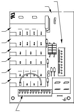
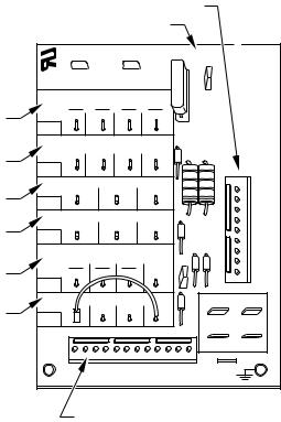
The unit must be configured to operate properly with system components with which it is installed. To successfully configure a basic system (see information printed on circuit board label located next to select pins), move the 6 select wires to the pins which match the components used (See Fig. 8).
a.GAS HEAT/CFM—SELECT GAS HEAT INPUT SIZE Factory selected gas heat size should correspond to unit label.
b.AC/HP SIZE—SELECT SYSTEM SIZE INSTALLED
Factory selected air conditioner size should correspond to capacity of unit installed. Installer should verify air conditioner size to ensure that airflow delivered falls within proper range for the size unit installed. This applies to all operational modes.
c.SYSTEM TYPE—SELECT SYSTEM TYPE INSTALLED
Factory selected on 48GP for AC-Air conditioner.
For Gas Heat/Electric Cool Unit–AC must be selected.
d.AC/HP CFM ADJUST—SELECT NOMINAL, LOW, OR HIGH AIRFLOW
The AC/HP CFM Adjust select is factory set to the High-HI (NOM for 060) tap. The CFM Adjust selections NOM/LO will regulate airflow supplied for all operational modes, except non-heat pump heating modes. HI provides 15 percent airflow over nominal unit size selected and LO provides 10 percent airflow below nominal unit size selected. Adjust selection options are provided to adjust airflow supplied to meet individual installation needs for such things as noise, comfort, and humidity removal (See Fig. 8, D as indicated).
e.ON/OFF DELAY—SELECT DESIRED TIME DELAY PROFILE
Four motor operation delay profiles are provided to customize and enhance system operation (See Fig. 8, E as indicated). Selection options are:
(1.) The standard 90 sec off delay (Factory Setting) at 100 percent airflow in cooling mode. In heating mode, IGC will control 45 sec on delay with no airflow and 45 sec off delay.
(2.) A 30 sec cooling delay with no airflow/ 90 sec off delay at 100 percent airflow profile is used when it is desirable to allow system coils time to cool-down in conjunction with the airflow in heating mode.
(3.) A no delay option used for servicing unit or when a thermostat is utilized to perform delay functions in cooling mode. In heating mode IGC will control 45 sec on delay with no airflow and 45 sec off delay.
(4.) Not recommended for 48GP
f.CONTINUOUS FAN—SELECT DESIRED FAN SPEED WHEN THERMOSTAT IS SET ON CONTINUOUS FAN
(1.) LO speed—Factory setting, 50 percent cooling mode airflow.
(2.) MED speed—Move connector to MED, 65 percent cooling mode airflow.
(3.) HI speed—Move connector to HI, 100 percent cooling mode airflow (See Fig. 8, F as indicated).
g.LOW-VOLTAGE CIRCUIT FUSING AND REFERENCE
The low-voltage circuit is fused by a board-mounted 5–amp automotive fuse placed in series with the transformer SEC2 and the R circuit. The C circuit of the transformer is referenced to chassis ground through a printed circuit run at SEC1 connected to metal standoff marked with ground symbol.
h.BASIC UNIT CONFIGURATION
The following basic configuration of the indoor motor will provide ARI rated performance of the 48GP. This BASIC CONFIGURATION should be used when the rated ARI performance is required, or if system enhancements such as super dehumidify are not needed.
(1.) HEAT-Factory selected to match heat input size.
3
(2.) AC/HP Size-Factory selected to match system size, please verify.
(3.) SYSTEM TYPE-Factory selected on 48GP system ACAIR CONDITIONER.
(4.) AC/HP CFM ADJUST-Select HIGH for 042 & 048, NOM for 036 & 060, and LO for 024 & 030..
(5.) ON/OFF DELAY-Factory selected 0/90 profile.
(6.) CONTINUOUS FAN-Select desired fan speed when thermostat is set to continuous fan.
i.COMFORT OPTIONS—SUPER DEHUMIDIFY (See Quick Reference Guide)
The Super Dehumidify option is possible when this unit is installed with a field supplied Thermidistat™ control (SuperDehumidify does not require an outdoor temperature sensor). The following configuration is recommended for maximum cooling/dehumidifying comfort. This configuration will improve the comfort provided by the air conditioning system if more humidity removal is desired. While providing this improved comfort, the system will operate efficiently, but not at the published ARI SEER efficiency. During cool-to-dehumidify call, it provides maximum dehumidification by reducing airflow to a minimum. The actual super dehumidify command from Thermidistat™ control to the indoor unit is a “Y” signal without a “G” signal in addition to dehumidify signal. The indoor unit responds to this combination by reducing the airflow to a minimum. All other characteristics of cool to dehumidify are the same.
The following system configuration is recommended for maximum cooling/dehumidifying comfort (See Fig. 8).
(1.) HEAT-Factory selected to match gas heat size of unit installed.
(2.) AC/HP Size-Factory selected to match system size, please verify.
(3.) SYSTEM TYPE-Factory selected on 48GP system ACAIR CONDITIONER.
(4.) AC/HP CFM ADJUST-Select NOM (Lo for 060). (5.) ON/OFF DELAY-Select ENH profile.
(6.) CONTINUOUS FAN-Select desired fan speed when thermostat is set to continuous fan.
(7.) DEHUMIDIFY MODE-Remove J1 jumper to activate.
NOTE: J1 jumper should only be removed when a Thermidistat™, humidistat or capable zoning control is installed.
(8.) LOW VOLTAGE CONNECTIONS-Make connections as shown in ELECTRICAL CONNECTIONS section.
(9.) CONFIGURE THERMIDISTAT™-Follow Thermidistat™ (or capable zoning system) installation instructions for Super Dehumidify operation.
ACCESSORY INSTALLATION
a.AUXILIARY TERMINALS
The AUX and HUM terminals on the Easy Select™ Board are tied directly to the G terminal, and provide a 24-v. signal whenever the G terminal is energized (See Fig. 6). During Super dehumidify mode, the G signal is not present and the auxiliary terminals are not energized. If the installation includes the use of this operating mode, do not use these terminals to control accessories. See Electronic Air Cleaner and Humidifier sections for further information.
b.ELECTRONIC AIR CLEANER CONNECTIONS
The AUX1 and AUX2 terminals are not always energized during blower operations, as described above. When using an
electronic air cleaner with the unit, use Airflow Sensor P/N. KEAAC0101AAA. The airflow sensor turns on electronic air cleaner when the blower is operating.
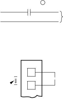
c.HUMIDIFIER/HUMIDISTAT CONNECTIONS
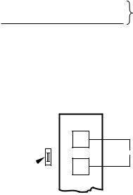
Easy Select™ Board terminals HUM1 and HUM2 are provided for direct connection to the low-voltage control of a humidifier through a standard humidistat (See Fig. 6). These terminals are energized with 24-v. when G thermostat signal is present (See Fig. 6 & 7). Alternately, the 24-v. signal may be sourced from the W and C on the 9 pin connector. When using a Thermidistat™ Control, Zone Comfort Plus or Comfort Zone II, the 24-v. signal may be sourced directly from the Thermidistat™ HUM terminal (See Fig. 6, 7 & 8).
|
|
HUMIDISTAT |
|||
HUM 1 |
|
|
|
|
|
|
|
|
|
|
|
|
|
|
|
|
|
(C) |
24-VAC |
|
|
|
TO HUMIDIFIER |
|
|
|
|||
|
|
|
|
||
HUM 2 |
|
|
|
|
|
(G) |
|
|
|
HUMIDIFIER WIRING |
|
|
|
|
|
||
|
|
|
|
|
A95317 |
Fig. 6—Humidifier Wiring-48GP
EASY SELECT
BOARD TERMINAL
BLOCK
J1 DH
 HUMIDISTAT
REMOVE R JUMPER
A95316
Fig. 7—Humidistat Wiring for
De-Humidify Mode-48GP
d.DEHUMIDIFY CAPABILITY WITH STANDARD HUMIDISTAT CONNECTION
Latent capacities for this unit are better than average systems. If increased latent capacity is an application requirement, the ICM board provides connection terminals for use of a standard humidistat. The unit will detect the humidistat contacts opening on increasing humidity and reduce its airflow to approximately 80 percent of nominal cooling mode airflow. This reduction will increase the system latent capacity until the humidity falls to a level which causes the humidistat to close its contacts. When the contacts close, the airflow will return to 100 percent of selected cooling airflow. To activate this mode, remove jumper J1 and wire in a standard humidistat (See Fig. 7).
e.DEHUMIDIFY AND SUPER DEHUMIDIFY CAPABILITIES
This model unit is capable of responding to a signal from indoor system control (Thermidistat™ or capable zoning control) to operate in comfort control modes such as Super Dehumidify Mode. Consult literature provided with indoor system control to determine if these operating modes are available, and to see control set up instructions. No special setup or wiring of unit is required.
48GP SEQUENCE OF OPERATION
a.CONTINUOUS FAN
(1.) Thermostat closes circuit R to G—The Blower runs at continuous fan airflow
4
b.COOLING MODE
(1.) If indoor temperature is above temperature set point and humidity is below humidity set point, thermostat closes circuits R to G, R to Y/Y2 and R to O—The unit delivers single speed cooling airflow.
c.COOLING MODE-DEHUMIDIFICATION
(1.) If indoor temperature is above temperature set point and humidity is above humidity set point, thermostat or Thermidistat™ closes circuits R to G, R to Y/Y2, R to O and humidistat or Thermidistat™ opens R to DH—The unit delivers airflow which is approximately 80 percent of the nominal cooling airflow to increase the latent capacity of the system.
d.COOLING MODE-SUPER DEHUMIDIFY OPERATION (SEE QUICK REFERENCE GUIDE)
NOTE: The indoor control used, such as a Thermidistat™, must be capable of providing Super Dehumidify operation mode and control must be configured as outlined in its installation instructions. Consult indoor control literature to determine if control is capable of providing Super Dehumidify inputs and for configuration instruction.
(1.) If the indoor temperature is below the temperature set point and the humidity is above the humidity set point, the Thermidistat™ closes circuit R to O, opens circuits R to DH and R to G, and closes circuit R to Y/Y2. If circuit R to G is closed (24-v.), the motor will deliver airflow at the full cooling or cooling plus dehumidify mode requested value. If circuit R to G is open (0–v.) for Super Dehumidify mode, the motor delivers reduced airflow to maximize the humidity removal of the system while minimizing over cooling.
e.GAS HEATING MODE
(1.) Thermostat closes circuit R to W/W1—The unit delivers the selected gas heat airflow. The IGC will control a 45 sec. blower “On” delay and a 45 sec. “Off” delay.
EASY SELECT™—48JZ
NOTE: Either the Carrier Thermidistat™ or Dual Fuel thermostat is required for operation of the dual-fuel (48JZ) units. Be sure to follow the installation instructions supplied with the Thermidistat™. Either indoor temperature control must use an outdoor air sensor to properly control heating operation.
EASY SELECT™ CONFIGURATION TAPS FOR 48JZ
Easy Select™ taps are used by the installer to configure a system. The ICM motor uses the selected taps to modify its operation to a pre-programmed table of airflows.
The unit must be configured to operate properly with system components with which it is installed. To successfully configure a basic system (see information printed on circuit board label located next to select pins), move the 6 select wires to the pins which match the components used (See Fig. 8).
a.GAS HEAT/CFM—SELECT GAS HEAT INPUT SIZE Factory selected gas heat size should correspond to unit label.
b.AC/HP SIZE—SELECT SYSTEM SIZE INSTALLED
Factory selected air conditioner size should correspond to capacity of unit installed. Installer should verify air conditioner size to ensure that airflow delivered falls within proper range for the size unit installed. This applies to all operational modes.
c.SYSTEM TYPE—SELECT SYSTEM TYPE INSTALLED
Factory selected on 48JZ for HP-EFF. SELECT OPTIONS
1. HP-COMFORT provides approximately 315 CFM/ton for higher normal heating air temperature and provides approxi-
|
|
9 PIN CONNECTOR |
|
|
||
ICM PRINTED CIRCUIT BOARD |
|
|
||||
|
SEC1 |
|
SEC2 |
|
J1 |
|
|
|
|
|
|
|
|
|
EASY SELECTTM |
|
|
|||
|
GAS HEAT/CFM |
|
|
|
||
|
090 |
060 |
040 |
N/A |
|
|
A |
1250 |
1100 |
800 |
|
|
|
VIO |
|
|
|
|
|
|
|
|
|
|
|
|
|
|
|
AC/HP SIZE |
|
|
|
|
B |
036 |
030 |
024 |
018 |
|
|
BLU |
|
|
|
|
|
|
|
|
|
|
|
|
|
|
SYSTEM TYPE |
|
|
DH |
||
C |
AC |
HP-COMFORT |
HP-EFF |
|
||
|
|
|
|
|
||
ORN |
|
|
|
|
R |
|
|
AC/HP CFM ADJUST |
|
W1 |
|||
D |
NOM |
LO |
|
HI |
|
W2 |
BLK |
|
|
|
|
Y1 |
|
|
ON/OFF DELAY |
|
|
Y/Y2 |
||
|
|
|
G |
|||
|
|
|
|
J2 |
|
|
|
0 |
30 |
0 |
|
O |
|
E |
ENH |
|
||||
90 |
90 |
0 |
|
|
C |
|
WHT |
|
|
|
|
||
|
|
|
|
|
|
|
|
CONTINUOUS FAN |
AUX1 |
HUM1 |
|||
|
LO |
MED |
HI |
YEL |
||
F |
|
|
||||
YEL |
|
|
|
|
|
|
|
|
|
|
|
|
|
|
|
|
|
|
AUX2 |
HUM2 |
|
|
|
|
|
24VAC |
|
|
|
HEATER/MOTOR |
GRY |
|
||
|
|
|
|
|||
12 PIN CONNECTOR
C01039
Fig. 8—Detail of SPP Printed-Circuit Board
mately 350 CFM/ton cooling airflow for good humidity removal
2. HP-EFF (factory selected) Provides equal airflow for heating and cooling modes to increase overall heat pump efficiency. Provides approximately 400 CFM/ton.
d.AC/HP CFM ADJUST—SELECT NOMINAL, LOW, OR HIGH AIRFLOW
The AC/HP CFM Adjust select is factory set to the High-HI (NOM for 036, 060) tap. The CFM Adjust selections NOM/LO will regulate airflow supplied for all operational modes, except non-heat pump heating modes. HI provides 15 percent airflow over nominal unit size selected and LO provides 10 percent airflow below nominal unit size selected. Adjust selection options are provided to adjust airflow supplied to meet individual installation needs for such things as noise, comfort, and humidity removal (See Fig. 8, D as indicated).
e.ON/OFF DELAY—SELECT DESIRED TIME DELAY PROFILE
Four motor operation delay profiles are provided to customize and enhance system operation (See Fig. 8, E as indicated). Selection options are:
(1.) The standard 90 sec off delay (Factory Setting) at 100 percent airflow in cooling or heat pump heating mode. In gas heating mode, IGC will control a 45 sec “On” delay and a 45 sec “Off” delay.
(2.) A 30 sec cooling delay with no airflow/ 90 sec off delay at 100 percent airflow profile is used when it is desirable to allow system coils time to cool-down/heat-up in conjunction with the airflow in cooling or heat pump heating mode.
(3.) A no delay option used for servicing unit or when a thermostat is utilized to perform delay functions. In gas heating mode IGC will control 45 sec on delay with no airflow and 45 sec off delay.
5
(4.) ENH (enhanced) selection provides a 30 sec. cooling & heat pump on delay with no airflow, plus 150 seconds at 70 percent airflow and no off delay for added comfort. This will minimize cold blow in heat pump operation and could enhance system efficiency.
f.CONTINUOUS FAN—SELECT DESIRED FAN SPEED WHEN THERMOSTAT IS SET ON CONTINUOUS FAN
(1.) LO speed—Factory setting, 50 percent cooling mode airflow.
(2.) MED speed—Move connector to MED, 65 percent cooling mode airflow.
(3.) HI speed—Move connector to HI, 100 percent cooling mode airflow (See Fig. 8, F as indicated).
g.LOW-VOLTAGE CIRCUIT FUSING AND REFERENCE
The low-voltage circuit is fused by a board-mounted 5–amp automotive fuse placed in series with the transformer SEC2 and the R circuit. The C circuit of the transformer is referenced to chassis ground through a printed circuit run at SEC1 connected to metal standoff marked with ground symbol.
h.BASIC UNIT CONFIGURATION
The following basic configuration of the indoor motor will provide ARI rated performance of the 48JZ. This BASIC CONFIGURATION should be used when the rated ARI performance is required.
(1.) HEAT-Factory selected to match heat input size.
(2.) AC/HP Size-Factory selected to match system size, please verify.
(3.) SYSTEM TYPE-Factory selected on 48JZ system for HP-EFF.
(4.) AC/HP CFM ADJUST-Select HIGH for 042 & 048, NOM for 036 & 060, and LO for 024 & 030.
(5.) ON/OFF DELAY-Factory selected 0/90 profile.
(6.) CONTINUOUS FAN-Select desired fan speed when thermostat is set to continuous fan.
i.COMFORT OPTIONS—SUPER DEHUMIDIFY (See Quick Reference Guide)
The Super Dehumidify option is possible when this unit is installed with a field supplied Thermidistat™ control (SuperDehumidify does not require an outdoor temperature sensor). The following configuration is recommended for maximum cooling/dehumidifying comfort. This configuration will improve the comfort provided by the air conditioning system if more humidity removal is desired. While providing this improved comfort, the system will operate efficiently, but not at the published ARI SEER efficiency.
The following system configuration is recommended for maximum cooling/dehumidifying comfort (See Fig. 8).
(1.) HEAT-Factory selected to match gas heat size of unit installed.
(2.) AC/HP Size-Factory selected to match system size, please verify.
(3.) SYSTEM TYPE-Factory selected on 48JZ system for HP-EFF.
(4.) AC/HP CFM ADJUST-Select NOM (Lo for 060). (5.) ON/OFF DELAY-Select ENH profile.
(6.) CONTINUOUS FAN-Select desired fan speed when thermostat is set to continuous fan.
(7.) LOW VOLTAGE CONNECTIONS-Make connections as shown in ELECTRICAL CONNECTIONS section.
(8.) CONFIGURE THERMIDISTAT™-Follow Thermidistat™ installation instructions for Super Dehumidify operation.
ACCESSORY INSTALLATION
a.AUXILIARY TERMINALS
The AUX and HUM terminals on the Easy Select™ Board are tied directly to the G terminal, and provide a 24-v. signal whenever the G terminal is energized (See Fig. 9). During Super dehumidify mode, the G signal is not present and the auxiliary terminals are not energized. If the installation includes the use of this operating mode, do not use these terminals to control accessories. See Electronic Air Cleaner and Humidifier sections for further information.
b.ELECTRONIC AIR CLEANER CONNECTIONS
The AUX1 and AUX2 terminals are not always energized during blower operations, as described above. When using an electronic air cleaner with the unit, use Airflow Sensor P/N. KEAAC0101AAA. The airflow sensor turns on electronic air cleaner when the blower is operating.
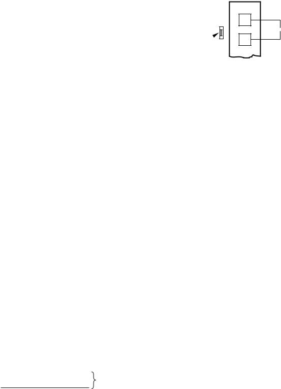
c.HUMIDIFIER / THERMIDISTAT™ CONNECTIONS
Easy Select™ Board terminals HUM1 and HUM2 are provided for direct connection to the low-voltage control of a humidifier through a standard Thermidistat™ (See Fig. 9). These terminals are energized with 24-v. when G thermostat signal is present (See Fig. 10). Alternately, the 24-v. signal may be sourced from the W and C on the 9 pin connector. When using a Thermidistat™ Control the 24-v. signal may be sourced directly from the Thermidistat™ HUM terminal (See Fig. 8, 9 & 10).
|
THERMIDISTAT ™ |
|
HUM 1 |
|
|
(C) |
24-VAC |
TO HUMIDIFIER |
|
HUM 2
(G)
HUMIDIFIER WIRING
C01108
Fig. 9—Humidifier Wiring-48JZ
EASY SELECT
BOARD TERMINAL
BLOCK
J1 DH


 THERMIDISTAT JUMPER
 R
R
C01109
Fig. 10—Thermidistat™ Wiring for
De-Humidify Mode-48JZ
d.DEHUMIDIFY CAPABILITY WITH STANDARD THERMIDISTAT™ CONNECTION
Latent capacities for this unit are better than average systems. If increased latent capacity is an application requirement, the ICM board provides connection terminals for use of a Thermidistat™. The unit will detect the Thermidistat™ contacts opening on increasing humidity and reduce its airflow to approximately 80 percent of nominal cooling mode airflow. This reduction will increase the system latent capacity until the humidity falls
6
to a level which causes the Thermidistat™ to close its contacts. When the contacts close, the airflow will return to 100 percent of selected cooling airflow. To activate this mode wire in Thermidistat™ see jumper in Fig. 10.
e.DEHUMIDIFY AND SUPER DEHUMIDIFY CAPABILITIES
This model unit is capable of responding to a signal from Thermidistat™ to operate in comfort control modes such as Super Dehumidify Mode. Consult literature provided with Thermidistat™ to determine if these operating modes are available, and to see control set up instructions. No special setup or wiring of unit is required.
48JZ SEQUENCE OF OPERATION
a.CONTINUOUS FAN
(1.) Thermostat closes circuit R to G—The Blower runs at continuous fan airflow
b.COOLING MODE
(1.) If indoor temperature is above temperature set point and humidity is below humidity set point, thermostat closes circuits R to G, R to Y/Y2 and R to O—The unit delivers single speed cooling airflow.
c.COOLING MODE-DEHUMIDIFICATION
(1.) If indoor temperature is above temperature set point and humidity is above humidity set point, Thermidistat™ closes circuits R to G, R to Y/Y2, R to O and Thermidistat™ opens R to DH—The unit delivers airflow which is approximately 80 percent of the nominal cooling airflow to increase the latent capacity of the system.
d.COOLING MODE-SUPER DEHUMIDIFY OPERATION (SEE QUICK REFERENCE GUIDE)
NOTE: Thermidistat™ is capable of providing Super Dehumidify operation mode and must be configured as outlined in its installation instructions. Consult indoor control literature to determine if control is capable of providing Super Dehumidify inputs and for configuration instruction.
(1.) If the indoor temperature is below the temperature set point and the humidity is above the humidity set point, the Thermidistat™ closes circuit R to O, opens circuits R to DH and R to G, and closes circuit R to Y/Y2. If circuit R to G is closed (24-v.), the motor will deliver airflow at the full cooling or cooling plus dehumidify mode requested value. If circuit R to G is open (0–v.) for super dehumidify mode, the motor delivers reduced airflow to maximize the humidity removal of the system while minimizing over cooling.
e. GAS HEATING MODE
(Occurs if outdoor temperature is below outdoor temperature change over setpoint.)
(1.) Thermostat closes circuit R to W/W1—The unit delivers the selected gas heat airflow. The IGC will control 45 sec. on delay with no airflow and 45 sec. off delay.
f. HEAT PUMP HEATING MODE
(Occurs if outdoor temperature is above outdoor temperature change over setpoint.)
(1.) Thermidistat™ closes circuit R to G and R to Y/Y2–The unit delivers selected heat pump heating airflow.
g.HEATING MODE—SUPER COMFORT HEAT OPERATION
NOTE: The Thermidistat™ is capable of providing Super Comfort Heat operation mode and must be configured as outlined in its installation instructions. The system must be installed with appropriate outdoor temperature sensor. Consult Thermidistat™ literature for configuration instructions. Consult sensor instructions for sensor installation details.
If the outdoor temperature is in the range of 12° to 40° F, the Thermidistat™ closes circuit R to Y/Y2 and opens circuit R to G. If circuit R to G is closed (24-v.), the motor will deliver airflow at the full heating requested value. If circuit R to G is open (0-v.) for maximum heating comfort, the motor delivers reduced airflow to maximize the temperature and minimize the draft effect of the heated air leaving the unit.
EASY SELECT™—50GL & 50JZ |
|
|
||||
|
|
9 PIN CONNECTOR |
|
|
||
ICM PRINTED CIRCUIT BOARD |
|
|
||||
|
SEC1 |
|
SEC2 |
|
J1 |
|
|
|
|
|
|
|
|
|
EASY SELECTTM |
|
|
|||
|
AUX HEAT KW/CFM |
|
|
|||
|
0-30 |
0-20 |
0-10 |
0-5 |
|
|
A |
1075 |
875 |
725 |
625 |
|
|
VIO |
|
|
|
|
|
|
|
|
|
|
|
|
|
|
|
AC/HP SIZE |
|
|
|
|
B |
036 |
030 |
024 |
018 |
|
|
BLU |
|
|
|
|
|
|
|
|
|
|
|
|
|
|
SYSTEM TYPE |
|
|
DH |
||
|
AC |
HP-COMFORT |
HP-EFF |
|
||
C |
ORN |
|
|
|
|
R |
|
AC/HP CFM ADJUST |
|
W1 |
|||
|
|
W2 |
||||
|
NOM |
|
LO |
HI |
|
|
D |
|
|
Y1 |
|||
BLK |
|
|
|
|
||
|
|
|
|
|
Y/Y2 |
|
|
|
|
|
|
|
|
|
ON/OFF DELAY |
|
|
G |
||
|
0 |
30 |
0 |
J2 |
|
O |
E |
90 |
90 |
0 |
ENH |
|
C |
|
|
|
|
|
||
|
WHT |
|
|
|
|
|
|
CONTINUOUS FAN |
AUX1 |
HUM1 |
|||
|
LO |
MED |
HI |
YEL |
||
F |
|
|
||||
YEL |
|
|
|
|
|
|
|
|
|
|
|
|
|
|
|
|
|
|
AUX2 |
HUM2 |
|
|
|
|
|
24VAC |
|
|
|
HEATER/MOTOR |
GRY |
|
||
|
|
|
|
|||
12 PIN CONNECTOR
C01033
Fig. 11—Detail of SPP Printed-Circuit Board
EASY SELECT™ CONFIGURATION TAPS FOR 50GL & 50JZ
Easy Select™ taps are used by the installer to configure a system. The ICM motor uses the selected taps to modify its operation to a pre-programmed table of airflows.
The unit must be configured to operate properly with system components with which it is installed. To successfully configure a basic system (see information printed on circuit board label located next to select pins), move the 6 select wires to the pins which match the components used.
a.AUX HEAT kW/CFM—SELECT HEATER RANGE FOR SIZE OF ELECTRIC HEATER INSTALLED
Installer must select the auxiliary heat airflow approved for application with kW size heater installed. If no heater is installed, this step can be skipped. Each select pin is marked with a range of heaters for which airflow (also marked), is approved. For increased comfort, select the narrowest kW range matching the heater size, for example, 0–10 for 10–kW heater. This airflow must be greater than the minimum for CFM for electric heater application with the size system installed for safe
7
and continuous operation. (See Tables 16, 17 & 18 for airflow delivery and minimum CFM.) Note that airflow marked is the airflow which will be supplied in emergency heat mode and heating mode on air conditioners when electric heat is the primary heating source. In heat pump heating mode when electric heaters are energized, the ICM will run the higher of heat pump heating airflow and electric heater airflow to ensure safe heater operation. The factory selection is the largest heater range approved (See Fig. 11, A as indicated).
b.AC/HP SIZE—SELECT SYSTEM SIZE INSTALLED
The factory setting for air conditioner or heat pump size is the size which matches the model of packaged unit installed. Installer should verify air conditioner or heat pump size to ensure that airflow delivered falls within proper range for the size unit installed. This applies to all operational modes with the exception of electric heat modes (See Fig. 11, B as indicated).
c.SYSTEM TYPE—SELECT SYSTEM TYPE INSTALLED
The type of system will be factory selected (see below for details):
(1.) AC-Air conditioner (Factory Selected for 50GL)
(2.) HP-COMFORT—Heat Pump Comfort provides approximately 315 CFM per ton for higher normal heating air delivery temperature and provides approximately 350 CFM per ton cooling airflow for good humidity removal.
(3.) HP-EFF (Factory Selected for 50JZ)— Heat Pump Efficiency provides same airflow for heating and cooling modes to increase overall HP efficiency; approximately 350 CFM per ton.
d.AC/HP CFM ADJUST—SELECT NOMINAL, LOW, OR HIGH AIRFLOW
The AC/HP CFM Adjust select is factory set to the High-Hi (NOM for 060) tap. The CFM Adjust selections NOM/LO will regulate airflow supplied for all operational modes, except non-heat pump heating modes. HI provides 15 percent airflow over nominal unit size selected and LO provides 10 percent airflow below nominal unit size selected. CFM Adjust selection options are provided to adjust airflow supplied to meet individual installation needs for such things as noise, comfort, and humidity removal (See Fig. 11, D as indicated).
e.ON/OFF DELAY—SELECT DESIRED TIME DELAY PROFILE
Four motor operation delay profiles are provided to customize and enhance system operation (See Fig. 11, E as indicated). Selection options are:
(1.) The standard 90 sec off delay (Factory Setting) at 100 percent airflow in cooling or heat pump heating mode.
(2.) A 30 sec cooling delay with no airflow/90 sec off delay at 100 percent airflow profile is used when it is desirable to allow system coils time to heat-up/cool-down in conjunction with the airflow in cooling or heat pump heating mode.
(3.) A no delay option used for servicing unit or when a thermostat is utilized to perform delay functions.
(4.) ENH, enhanced selection, provides a 30 sec cooling on delay with no airflow/ plus 150 sec at 70 percent airflow/ no off delay for added comfort.
This will minimize cold blow in heat pump operation (50JZ only) and could enhance system efficiency.
f.CONTINUOUS FAN—SELECT DESIRED FAN SPEED WHEN THERMOSTAT IS SET ON CONTINUOUS FAN
(1.) LO speed—Factory setting, 50 percent cooling mode airflow.
(2.) MED speed—Move connector to MED, 65 percent cooling mode airflow.
(3.) HI speed—Move connector to HI, 100 percent cooling mode airflow (See Fig. 11, F as indicated).
g.LOW-VOLTAGE CIRCUIT FUSING AND REFERENCE
The low-voltage circuit is fused by a board-mounted 5–amp automotive fuse placed in series with the transformer SEC2 and the R circuit. The C circuit of the transformer is referenced to chassis ground through a printed circuit run at SEC1 connected to metal standoff marked with ground symbol.
h.BASIC UNIT CONFIGURATION
The following basic configuration of the indoor motor will provide ARI rated performance of the System. This BASIC CONFIGURATION should be used when the rated ARI performance is required, or if system enhancements such as super dehumidify are not needed.
(1.) AUX HEAT kW/CFM-Select the heater range for the size of electric heater installed (skip this step if no heater is installed).
(2.) AC/HP SIZE-Factory selected to match system size installed, please verify.
(3.) SYSTEM TYPE-Factory selected AC (50GL) or HP-EFF (50JZ).
(4.) AC/HP CFM ADJUST-Select HIGH for 042 & 048, NOM for 036 & 060, and LO for 024 & 030.
(5.) ON/OFF DELAY-Select 0/90 profile.
(6.) CONTINUOUS FAN-Select desired fan speed when thermostat is set to continuous fan.
i.COMFORT OPTIONS—SUPER DEHUMIDIFY (See Quick Reference Guide)
The Super Dehumidify option is possible when this unit is installed with a field supplied Thermidistat™ control (Super Dehumidify does not require an outdoor temperature sensor). The following configuration is recommended for maximum cooling/dehumidifying comfort: This configuration will improve the comfort provided by the air conditioning system if more humidity removal is desired. While providing this improved comfort, the system will operate efficiently, but not at the published HSPF or ARI SEER efficiency.
The following system configuration is recommended for maximum heating and cooling/dehumidifying comfort (See Fig. 11). (1.) AUX HEAT kW/CFM-Select the narrowest heater range to match size of electric heater installed (skip this step if no
heater is installed).
(2.) AC/HP Size-Factory selected to match system size installed, please verify.
(3.) SYSTEM TYPE-Select system type HP-COMFORT (for heat pump system) or AC (for air conditioner system).
(4.) AC/HP CFM ADJUST-Select NOM (Lo for 060). (5.) ON/OFF DELAY-Select ENH profile.
(6.) CONTINUOUS FAN-Select desired fan speed when thermostat is set to continuous fan.
(7.) DEHUMIDIFY MODE-Remove J1 jumper to activate.
(8.) LOW VOLTAGE CONNECTIONS-Make connections as shown in ELECTRICAL CONNECTIONS section.
(9.) CONFIGURE THERMIDISTAT™ (or capable zoning system)-Following its installation instructions for Super Dehumidify and Super Comfort Heat operation.
8
This configuration provides the following comfort enhancements:
(a.) A 30 sec blower on delay with 150 sec at 70 percent airflow to allow the indoor coil to warm up or cool down before the blower is asked to deliver 100 percent airflow reducing the cold blow sensation at start up in heating and allowing the indoor coil to more quickly reach wet coil operating conditions in cooling.
(b.) A no blower off delay eliminates cold blow which may be associated with running the blower after shut down of the compressor and avoids re-evaporation of condensed moisture after cooling/dehumidifying operation.
(c.) Lower airflow while the compressor is running to reduce draft effects and increase heating air temperature and improved humidity control during cooling operation.
ACCESSORY INSTALLATION
a.ACCESSORY ELECTRIC HEATERS
Electric heaters may be installed with the 50GL & 50JZ units per instructions supplied with electric heater package. See unit rating plate for factory-approved electric heater kits.
b.AUXILIARY TERMINALS
The AUX and HUM terminals on the Easy Select™ Board are tied directly to the G terminal, and provide a 24-v. signal whenever the G terminal is energized (See Fig. 12). During Super dehumidify mode, the G signal is not present and the auxiliary terminals are not energized. If the installation includes the use of the operating mode, do not use these terminals to control accessories. See Electronic Air Cleaner and Humidifier sections for further information.
c.ELECTRONIC AIR CLEANER CONNECTIONS
The AUX1 and AUX2 terminals are not always energized during blower operations, as described above. When using an electronic air cleaner with the unit, use Airflow Sensor P/N KEAAC0101AAA. The airflow sensor turns on electronic air cleaner when the blower is operating.
d.HUMIDIFIER/HUMIDISTAT CONNECTIONS
Easy Select™ Board terminals HUM1 and HUM2 are provided for direct connection to the low-voltage control of a humidifier through a standard humidistat (See Fig. 12). These terminals are energized with 24-v. when G thermostat signal is present. (See Fig. 11, 12 & 13). Alternately, the 24-v. signal may be sourced from the W and C circuit board connections. When using a Thermidistat™ Control, Zone Comfort Plus or Comfort Zone II, the 24-v. signal may be sourced directly from the Thermidistat™ HUM terminal.
|
|
HUMIDISTAT |
|||
HUM 1 |
|
|
|
|
|
|
|
|
|
|
|
|
|
|
|
|
|
(C) |
24-VAC |
|
|
|
TO HUMIDIFIER |
|
|
|
|||
|
|
|
|
||
HUM 2 |
|
|
|
|
|
(G) |
|
|
|
HUMIDIFIER WIRING |
|
|
|
|
|
||
|
|
|
|
|
A95317 |
Fig. 12—Humidifier Wiring for 50GL & 50JZ
e.DEHUMIDIFY CAPABILITY WITH STANDARD HUMIDISTAT CONNECTION
Latent capacities for these units are better than average systems. If increased latent capacity is an application requirement, the circuit board provides connection terminals for use of a
EASY SELECT
BOARD TERMINAL
BLOCK
J1 DH
 HUMIDISTAT
REMOVE R JUMPER
A95316
Fig. 13—Humidistat Wiring for De-Humidify Modefor 50GL & 50JZ
standard humidistat. The unit will detect the humidistat contacts opening on increasing humidity and reduce its airflow to approximately 80 percent of nominal cooling mode airflow. This reduction will increase the system latent capacity until the humidity falls to a level which causes the humidistat to close its contacts. When the contacts close, the airflow will return to 100 percent of selected cooling airflow. To activate this mode, remove jumper J1 and wire in a standard humidistat ( See Fig. 13).
f.DEHUMIDIFY AND SUPER DEHUMIDIFY CAPABILITIES
these models are capable of responding to a signal from indoor system control (thermostat, Thermidistat™, zoning control) to operate in comfort control modes such as Super Dehumidify Mode. Consult literature provided with indoor system control to determine if these operating modes are available, and to see control set up instructions. No special setup or wiring of unit is required.
50GL & 50JZ SEQUENCE OF OPERATION
a.CONTINUOUS FAN
(1.) Thermostat closes circuit R to G—The Blower runs at continuous fan airflow.
b.COOLING MODE-LOW HUMIDITY
(1.) If indoor temperature is above temperature set point and humidity is below humidity set point, thermostat closes circuits R to G, R to Y/Y2 and R to O—The unit delivers cooling airflow.
c.COOLING MODE-DEHUMIDIFICATION
(1.) If indoor temperature is above temperature set point and humidity is above humidity set point, thermostat or Thermidistat™ closes circuits R to G, R to O, and R to Y/Y2 and humidistat or Thermidistat™ opens R to DH—The unit delivers airflow which is approximately 80 percent of the nominal cooling airflow to increase the latent capacity of the system.
d.COOLING MODE-SUPER DEHUMIDIFY OPERATION (see quick reference guide)
NOTE: The indoor control used, such as a Thermidistat™, must be capable of providing Super Dehumidify operation mode and control must be configured as outlined in its installation instructions. Consult indoor control literature to determine if control is capable of providing Super Dehumidify inputs and for configuration instruction.
(1.) If the indoor temperature is below the temperature set point and the humidity is above the humidity set point, the Thermidistat™ closes circuit R to O, opens circuits R to DH and R to G, and cycles circuit R to Y/Y2. If circuit R to G is closed (24-v.), the motor will deliver airflow at the full cooling or cooling plus dehumidify mode requested
9
 Loading...