


50EJ,EK,EW,EY024-048 Single-Package Rooftop Units Electric Cooling with Electric Heat Option
Installation, Start-Up and
Service Instructions
CONTENTS
Page
SAFETY CONSIDERATIONS . . . . . . . . . . . . . . . . . . 1
INSTALLATION . . . . . . . . . . . . . . . . . . . . . . . . . . . . 1-31
Step 1 Ð Provide Unit Support . . . . . . . . . . . . . . 1
·ROOF CURB
·ALTERNATE UNIT SUPPORT
Step 2 Ð Rig and Place Unit . . . . . . . . . . . . . . . . . 8
·POSITIONING
·ROOF MOUNT
Step 3 Ð Field Fabricate Ductwork . . . . . . . . . . . 11 Step 4 Ð Make Unit Duct Connections . . . . . . . 11 Step 5 Ð Trap Condensate Drain . . . . . . . . . . . . . 11 Step 6 Ð Controls Options . . . . . . . . . . . . . . . . . . 12
·CONSTANT VOLUME APPLICATIONS
·VARIABLE AIR VOLUME (VAV)
APPLICATIONS
Step 7 Ð Make Electrical Connections . . . . . . . 15
·POWER WIRING
·FIELD POWER SUPPLY
·FIELD CONTROL WIRING
Step 8 Ð Make Outdoor-Air Inlet
Adjustments . . . . . . . . . . . . . . . . . . . . . . . . . . . . . . . 25
·ECONOMIZER
·ECONOMIZER SETTINGS
Step 9 Ð Position Power Exhaust/
Barometric Relief Damper Hood . . . . . . . . . . . . . 29 Step 10 Ð Install Accessories . . . . . . . . . . . . . . . 30
START-UP . . . . . . . . . . . . . . . . . . . . . . . . . . . . . . . . 32-42 SERVICE . . . . . . . . . . . . . . . . . . . . . . . . . . . . . . . . . . 42-45 TROUBLESHOOTING . . . . . . . . . . . . . . . . . . . . . . 46-51 START-UP CHECKLIST . . . . . . . . . . . . . . . CL-1, CL-2
SAFETY CONSIDERATIONS
Installation and servicing of air-conditioning equipment can be hazardous due to system pressure and electrical components. Only trained and quali®ed service personnel should install, repair, or service air-conditioning equipment.
Untrained personnel can perform basic maintenance functions of cleaning coils and ®lters and replacing ®lters. All other operations should be performed by trained service personnel. When working on air-conditioning equipment, observe precautions in the literature, tags and labels attached to the unit, and other safety precautions that may apply.
Follow all safety codes. Wear safety glasses and work gloves. Use quenching cloth for unbrazing operations. Have ®re extinguishers available for all brazing operations.
Before performing service or maintenance operations on unit, turn off main power switch to unit. Electrical shock could cause personal injury.
IMPORTANT Ð READ BEFORE INSTALLING
IMPORTANT: Due to upgrades in unit control software and hardware, units produced currently are slightly different than original design units. The unit control software (which has changed) is designated with a sticker on the unit control board, chip U8 (the large chip in the center of the board), which states the software Version number. Version 1.0 is the original version. Version 2.0 is the current version. Differences in installation, con®guration, and start-up procedures in this manual will be identi®ed by Version number.
INSTALLATION
Step 1 Ð Provide Unit Support
All panels must be in place when rigging. Unit is not designed for handling by fork truck.
ROOF CURB Ð Assemble and install accessory roof curb in accordance with instructions shipped with the curb. Accessory roof curb and information required to ®eld fabricate a roof curb or horizontal adapter are shown in Fig. 1 and 2. Install insulation, cant strips, roo®ng, and counter ¯ashing as shown. Ductwork can be secured to roof curb before unit is set in place.
IMPORTANT: The gasketing of the unit to the roof curb is critical for a leak-proof seal. Install gasket supplied with the roof curb as shown in Fig. 1. Improperly applied gasket can result in air leaks and poor unit performance.
Curb should be level. This is necessary to permit unit drain to function properly. Unit leveling tolerance is shown in Fig 1 and 2. Refer to Accessory Roof Curb Installation Instructions for additional information as required. When accessory roof curb is used, unit may be installed on class A, B, or C roof covering material.
ALTERNATE UNIT SUPPORT Ð When the curb or adapter cannot be used, support unit with sleepers using unit curb or adapter support area. If sleepers cannot be used, support long sides of unit (refer to Fig. 3-6) with a minimum number of equally spaced 4-in. x 4-in. pads as follows: 50EJ,EK,EW,EY024-034 units require 3 pads on each side; 50EJ,EK,EW,EY038-048 require 4 pads on each side. Unit may sag if supported by corners only.
Manufacturer reserves the right to discontinue, or change at any time, speci®cations or designs without notice and without incurring obligations.
Book |
1 |
|
PC 111 |
Catalog No. 535-006 |
Printed in U.S.A. |
Form 50E-3SI |
Pg 1 |
8-96 |
Replaces: 50E-1SI |
Tab |
1b |
|
|
|
|
|
|
|
|
|
|
|
|
|
|
|
|
|
|
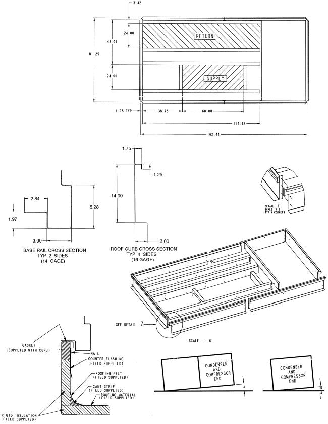
NOTES:
1.Unless otherwise speci®ed, all dimensions are to outside of part.
2.Roof curb accessory is shipped disassembled.
3.All roof curb parts are to be 16 ga galvanized steel.
4.Dimensions are in inches.
NOTE: To prevent standing water in the drain pan of the indoor section and the heat exchangers, UNIT CAN ONLY BE PITCHED AS SHOWN.
UNIT LEVELING TOLERANCES DIMENSIONS*
(Degrees and Inches)
|
A |
|
B |
||
Deg. |
|
in. |
Deg. |
|
in. |
1.0 |
|
2.9 |
.50 |
|
.75 |
|
|
|
|
|
|
*From edge of unit to horizontal.
Fig. 1 Ð Roof Curb (Sizes 024-034)
2

NOTES:
1.Unless otherwise speci®ed, all dimensions are to outside of part.
2.Roof curb accessory is shipped disassembled.
3.All roof curb parts are to be 16 ga galvanized steel.
4.Dimensions are in inches.
NOTE: To prevent standing water in the drain pan of the indoor section and the heat exchangers, UNIT CAN ONLY BE PITCHED AS SHOWN.
UNIT LEVELING TOLERANCES DIMENSIONS*
(Degrees and Inches)
|
A |
|
B |
||
Deg. |
|
in. |
Deg. |
|
in. |
1.0 |
|
2.9 |
.50 |
|
.75 |
|
|
|
|
|
|
*From edge of unit to horizontal.
Fig. 2 Ð Roof Curb (Sizes 038-048)
3
-
UNIT SIZE |
OPERATING |
A |
B |
CORNER WEIGHT |
||||
WEIGHT |
|
|
(lb) |
|
||||
50EJ/EK |
|
|
|
|
|
|||
(lb) |
ft-in. |
ft-in. |
1 |
2 |
|
3 |
4 |
|
|
|
|||||||
024 |
4016 |
5-113¤8 |
3-511¤16 |
823 |
914 |
|
1199 |
1080 |
028 |
4102 |
5- 81¤2 |
3-75¤8 |
844 |
859 |
|
1210 |
1189 |
030 |
4102 |
5- 81¤2 |
3-75¤8 |
844 |
859 |
|
1210 |
1189 |
034 |
4102 |
5- 81¤2 |
3-75¤8 |
844 |
859 |
|
1210 |
1189 |
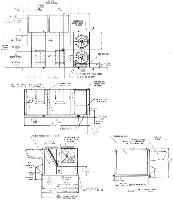
Fig. 3 Ð Base Unit Dimensions, 50EJ/EK024-034
4
NOTES: |
LEGEND |
|
1. |
Weights include economizer (Std) |
|
2. |
Center of gravity. |
VFD Ð Variable Frequency Drive |
3.Do not locate adjacent units with discharge facing economizer inlet. Minimum clearances to be:
Adjacent Units: 158-09 Top of Units: No overhang Condenser Coil: 48-09 Economizer Side: 68-09
Filter Access Side: 108-09 (for removal of evaporator coil)
4.For smaller service and operational clearances, contact Carrier Application Engineering department.
5.Bottom ducts designed to be attached to accessory roof curb. If unit is
mounted on dunnage, it is recommended the ducts be supported by cross braces as done on accessory roof curb.
6. Dimensions are in inches. Dimensions in [ ] are in millimeters.
7.For units with electric heat, a ®eld-supplied 90° elbow must be installed in the supply ductwork below the unit discharge.
UNIT SIZE |
OPERATING |
A |
B |
CORNER WEIGHT |
||||
WEIGHT |
|
(lb) |
|
|||||
50E |
|
|
|
|
||||
(lb) |
ft-in. |
ft-in. |
1 |
2 |
3 |
4 |
||
|
||||||||
J038 |
4282 |
7-75¤16 |
3-101¤2 |
961 |
858 |
1162 |
1302 |
|
J/K044 |
4508 |
7-313¤16 |
3-111¤2 |
973 |
868 |
1258 |
1409 |
|
J048 |
4795 |
7-23¤16 |
3-103¤32 |
1007 |
915 |
1368 |
1505 |
|
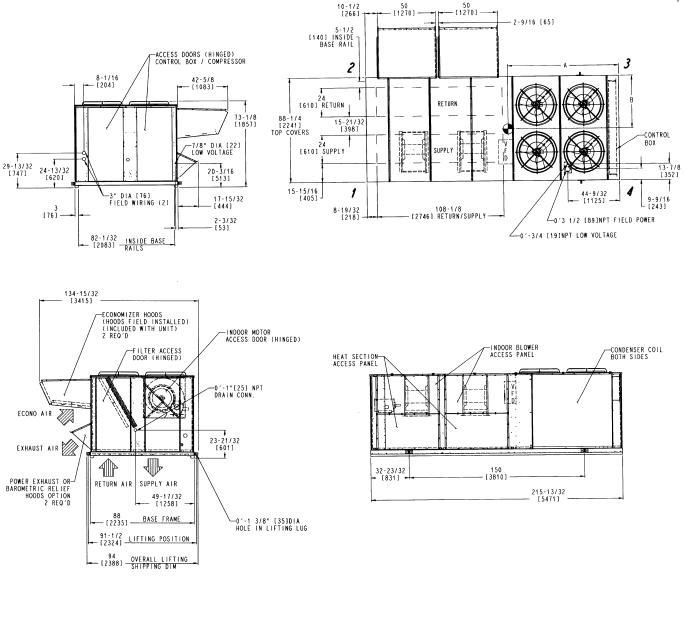
Fig. 4 Ð Base Unit Dimensions, 50EJ038-048 and 50EK044
5
NOTES:
1.Weights include economizer (Std)
2. Center of gravity.
3.Do not locate adjacent units with discharge facing economizer inlet. Minimum clearances to be:
Adjacent Units: 158-09 Top of Units: No overhang Condenser Coil: 48-09 Economizer Side: 68-09
Filter Access Side: 108-09 (for removal of evaporator coil)
4.For smaller service and operational clearances, contact Carrier Application Engineering department.
5.Dimensions are in inches. Dimensions in [ ] are in millimeters.
6.For units equipped with electric heat, a ®eld-supplied 90° elbow must be installed in the supply ductwork below the unit discharge.
7.For side-supply/return applications, a single return and supply ductwork connection is recommended for covering both return and both supply openings.
LEGEND
VFD Ð Variable Frequency Drive
UNIT SIZE |
OPERATING |
A |
B |
CORNER WEIGHT |
||||
WEIGHT |
|
|
(lb) |
|
||||
50EW/EY |
|
|
|
|
|
|||
(lb) |
ft-in. |
ft-in. |
1 |
2 |
|
3 |
4 |
|
|
|
|||||||
024 |
4016 |
5-113¤8 |
3-511¤16 |
823 |
914 |
|
1199 |
1080 |
028 |
4102 |
5- 81¤2 |
3-75¤8 |
844 |
859 |
|
1210 |
1189 |
030 |
4102 |
5- 81¤2 |
3-75¤8 |
844 |
859 |
|
1210 |
1189 |
034 |
4102 |
5- 81¤2 |
3-75¤8 |
844 |
859 |
|
1210 |
1189 |
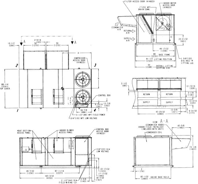
Fig. 5 Ð Base Unit Dimensions, 50EW/EY024-034
6
NOTES:
1.Weights include economizer (Std)
2. Center of gravity.
3.Do not locate adjacent units with discharge facing economizer inlet. Minimum clearances to be:
Adjacent Units: 158-09 Top of Units: No overhang Condenser Coil: 48-09 Economizer Side: 68-09
Filter Access Side: 108-09 (for removal of evaporator coil)
4.For smaller service and operational clearances, contact Carrier Application Engineering department.
5. Dimensions are in inches. Dimensions in [ ] are in millimeters.
6.For units equipped with electric heat, a ®eld-supplied 90° elbow must be installed in the supply ductwork below the unit discharge.
7.For side-supply/return applications, a single return and supply ductwork connection is recommended for covering both return and both supply air openings.
LEGEND
VFD Ð Variable Frequency Drive
UNIT SIZE |
OPERATING |
A |
B |
CORNER WEIGHT |
||||
|
(lb) |
|
||||||
50E |
WEIGHT |
|
|
|
|
|||
(lb) |
ft-in. |
ft-in. |
1 |
2 |
3 |
4 |
||
|
||||||||
W038 |
4282 |
7-75¤16 |
3-101¤2 |
961 |
858 |
1162 |
1302 |
|
W/Y044 |
4508 |
7-313¤16 |
3-111¤2 |
973 |
868 |
1258 |
1409 |
|
W048 |
4795 |
7-23¤16 |
3-103¤32 |
1007 |
915 |
1368 |
1505 |
|
Fig. 6 Ð Base Unit Dimensions, 50EW038-048 and 50EY044
7
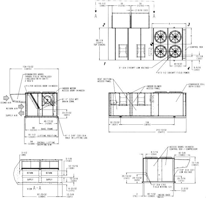
Step 2 Ð Rig and Place Unit Ð Inspect unit for transportation damage. File any claim with transportation agency. Keep unit upright, and do not drop. Use spreader bars over unit to prevent sling or cable damage. Rollers may be used to move unit across a roof. Level by using unit frame as a reference; leveling tolerance is shown in Fig. 1 and 2. See Fig. 7 for additional information. Unit weight is shown in Table 1.
NOTE: On retro®t jobs, ductwork may be attached to old unit instead of roof curb. Be careful not to damage ductwork when removing unit. Attach existing ductwork to roof curb instead of unit.
Four lifting lugs are provided on the unit base rails as shown in Fig. 7. Refer to rigging instructions on unit.
POSITIONING Ð Provide clearance around and above unit for air¯ow, safety, and service access (Fig. 3-6).
Do not install unit in an indoor location. Do not locate air inlets near exhaust vents or other sources of contaminated air.
Although unit is weatherproof, guard against water from higher level runoff and overhangs.
NOTICE TO RIGGERS:
ALL PANELS MUST BE IN PLACE
WHEN RIGGING.
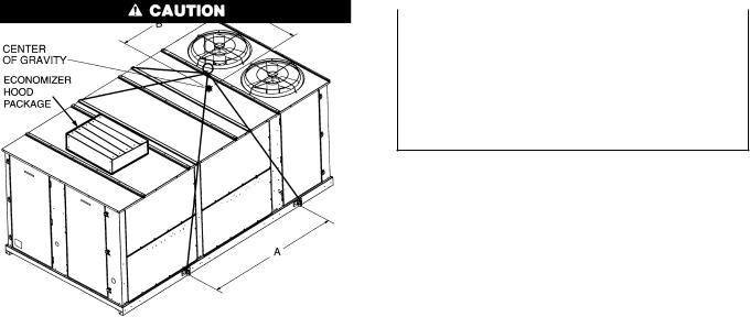
NOTE: Rig with four cables and spread with two 92 in. (2337 mm) spreader bars. Maintain a distance of 74 in. (1880 mm) from top of unit to eyehook.
NOTE:
Add 32 lb (14.5 kg) for domestic crating.
Add 312 lb (142 kg) for export crating (024-034 units). Add 346 lb (157 kg) for export crating (038-048 units). Add 250 lb (113 kg) for power exhaust.
Add 220 lb (100 kg) for copper condenser coil (024-034 units). Add 285 lb (129 kg) for copper condenser coil (038-044 units). Add 380 lb (172 kg) for copper condenser coil (048 unit).
MODEL |
WEIGHT |
|
A |
|
B |
|
C |
||||
50EJ/EK/EW/EY |
lb |
kg |
in. |
|
mm |
in. |
|
mm |
in. |
|
mm |
024 |
4016 |
1822 |
87.68 |
|
2227 |
71.4 |
|
1814 |
41.7 |
|
1059 |
028 |
|
|
|
|
|
|
|
|
|
|
|
030 |
4102 |
1860 |
87.68 |
|
2227 |
68.5 |
|
1740 |
43.6 |
|
1107 |
034 |
|
|
|
|
|
|
|
|
|
|
|
038* |
4282 |
1942 |
|
|
|
91.3 |
|
2319 |
46.5 |
|
1181 |
044 |
4508 |
2045 |
150 |
|
3810 |
87.8 |
|
2230 |
46.5 |
|
1181 |
048* |
4795 |
2175 |
|
|
|
86.2 |
|
2189 |
46.1 |
|
1171 |
|
|
|
|
|
|
|
|
|
|
|
|
*Sizes 038 and 048 are 50EJ,EW units only.
Fig. 7 Ð Rigging Label
8
Table 1 Ð Physical Data
UNIT 50EJ,EK,EW,EY |
|
024 |
|
|
028 |
|
|
|
030 |
|
|
|
034 |
|
NOMINAL CAPACITY (tons) |
|
20 |
|
|
25 |
|
|
|
27 |
|
|
|
30 |
|
OPERATING WEIGHT (lb)* |
|
|
|
|
|
|
|
|
|
|
|
|
|
|
Unit |
|
|
|
|
|
|
|
|
|
|
|
|
|
|
Al/Al² |
|
4016 |
|
|
4102 |
|
|
|
4102 |
|
|
|
4102 |
|
Al/Cu² |
|
4236 |
|
|
4322 |
|
|
|
4322 |
|
|
|
4322 |
|
Roof Curb (14-in. curb) |
|
365 |
|
|
365 |
|
|
|
365 |
|
|
|
365 |
|
COMPRESSOR |
|
|
|
|
|
|
|
|
|
|
|
|
|
|
Type Ckt 1 |
|
06D328 |
|
|
06D328 |
|
|
|
06D537 |
|
|
06D537 |
|
|
Ckt 2 |
|
06D818 |
|
|
06D328 |
|
|
|
06D328 |
|
|
06D537 |
|
|
Number of Refrigerant Circuits |
|
2 |
|
|
2 |
|
|
|
2 |
|
|
|
2 |
|
Oil (oz) (Ckt1, Ckt 2) |
|
115, 88 |
|
|
115 ea. |
|
|
|
115 ea. |
|
|
115 ea. |
|
|
REFRIGERANT TYPE |
|
|
|
|
|
|
R-22 |
|
|
|
|
|
|
|
Operating Charge (lb-oz) |
|
|
|
|
|
|
|
|
|
|
|
|
|
|
Circuit 1** |
|
25-0 |
|
|
25-0 |
|
|
|
25-0 |
|
|
|
25-0 |
|
Circuit 2 |
|
31-0 |
|
|
25-0 |
|
|
|
25-0 |
|
|
|
25-0 |
|
CONDENSER COIL |
|
|
|
Cross-Hatched 3¤89 Copper Tubes, Aluminum Lanced or Copper Fins |
|
|
|
|||||||
Quantity |
|
1 |
|
|
1 |
|
|
|
1 |
|
|
|
1 |
|
Rows...Fins/in. |
|
4...15 |
|
|
4...15 |
|
|
|
4...15 |
|
|
|
4...15 |
|
Total Face Area (sq ft) |
|
33.3 |
|
|
33.3 |
|
|
|
33.3 |
|
|
|
33.3 |
|
CONDENSER FAN |
|
|
|
|
|
Propeller Type |
|
|
|
|
|
|
||
Nominal Cfm |
|
13,420 |
|
|
13,420 |
|
|
|
13,420 |
|
|
|
13,420 |
|
Quantity...Diameter (in.) |
|
2...30 |
|
|
2...30 |
|
|
|
2...30 |
|
|
|
2...30 |
|
Motor Hp (1075 Rpm) |
|
1 |
|
|
1 |
|
|
|
1 |
|
|
|
1 |
|
EVAPORATOR COIL |
|
|
Cross-Hatched 3¤89 Copper Tubes, Aluminum or Copper Plate Fins, Intertwined Circuits |
|
|
|||||||||
Rows...Fins/in. |
|
4...15 |
|
|
4...15 |
|
|
|
4...15 |
|
|
|
4...15 |
|
Total Face Area (sq ft) |
|
31.7 |
|
|
31.7 |
|
|
|
31.7 |
|
|
|
31.7 |
|
|
|
|
|
|
|
|
|
|
|
|
|
|
|
|
EVAPORATOR FAN |
|
|
|
|
|
Centrifugal Type |
|
|
|
|
|
|
||
Quantity...Size (in.) |
|
2...20x15 |
|
|
2...20x15 |
|
|
|
2...20x15 |
|
|
2..20x15 |
|
|
Type Drive |
|
Belt |
|
|
Belt |
|
|
|
Belt |
|
|
Belt |
|
|
Nominal Cfm |
|
8,000 |
|
|
10,000 |
|
|
|
11,000 |
|
|
|
12,000 |
|
Motor Hp |
5 |
10²² |
15 |
7.5 |
10²² |
15 |
|
10 |
15²² |
|
20 |
10 |
15²² |
20 |
Motor Frame Size |
S184T |
S215T |
S254T |
S213T |
S215T |
S254T |
|
S215T |
S254T |
|
S256T |
S215T |
S254T |
S256T |
Motor Bearing Type |
|
Ball |
|
|
Ball |
|
|
|
Ball |
|
|
|
Ball |
|
Maximum Allowable Rpm |
|
1200 |
|
|
1200 |
|
|
|
1200 |
|
|
|
1200 |
|
Motor Pulley Pitch Diameter |
4.6 |
6.6 |
6.9 |
4.9 |
6.1 |
7.1 |
|
6.6 |
6.7 |
|
7.5 |
6.4 |
6.9 |
7.5 |
Nominal Motor Shaft Diameter (in.) |
11¤8 |
13¤8 |
15¤8 |
13¤8 |
13¤8 |
15¤8 |
|
13¤8 |
15¤8 |
|
15¤8 |
13¤8 |
15¤8 |
15¤8 |
Fan Pulley Pitch Diameter (in.) |
11.1 |
12.5 |
11.1 |
11.1 |
11.1 |
11.1 |
|
13.7 |
11.1 |
|
11.1 |
12.5 |
11.1 |
11.1 |
Nominal Fan Shaft Diameter (in.) |
|
111¤16 |
|
|
111¤16 |
|
|
|
111¤16 |
|
|
|
111¤16 |
|
Belt, Quantity...Type |
1...BX59 |
1...BX60 |
1...5VX590 |
1...BX56 |
1...BX56 |
1...5VX590 |
1...BX62 |
1...5VX590 |
1...5VX600 |
1...BX60 |
1...5VX590 |
1...5VX600 |
||
Belt, Length (in.) |
62 |
63 |
59 |
59 |
59 |
59 |
|
65 |
59 |
|
60 |
63 |
59 |
60 |
Pulley Center Line Distance (in.) |
16.0-18.7 |
15.6-18.4 |
15.0-17.9 |
15.6-18.4 |
15.6-18.4 |
15.0-17.9 |
15.6-18.4 |
15.0-17.9 |
15.6-18.4 |
15.0-17.9 |
||||
Factory Speed Setting (rpm) |
725 |
924 |
1088 |
773 |
962 |
1119 |
|
843 |
1056 |
|
1182 |
896 |
1088 |
1182 |
HIGH-PRESSURE SWITCH (psig) |
|
|
|
|
|
|
|
|
|
|
|
|
|
|
Cutout |
|
426 |
|
|
426 |
|
|
|
426 |
|
|
|
426 |
|
Reset (Auto.) |
|
320 |
|
|
320 |
|
|
|
320 |
|
|
|
320 |
|
LOW-PRESSURE SWITCH (psig) |
|
|
|
|
|
|
|
|
|
|
|
|
|
|
Cutout |
|
7 |
|
|
7 |
|
|
|
7 |
|
|
|
7 |
|
Reset (Auto.) |
|
22 |
|
|
22 |
|
|
|
22 |
|
|
|
22 |
|
RETURN-AIR FILTERS |
|
|
|
|
|
|
|
|
|
|
|
|
|
|
Quantity...Size (in.) |
|
10...20x24x2 |
|
10...20x24x2 |
|
|
10...20x24x2 |
|
|
10...20x24x2 |
||||
OUTDOOR-AIR FILTERS |
|
8...16x25 |
|
|
8...16x25 |
|
|
|
8...16x25 |
|
|
8...16x25 |
|
|
Quantity...Size (in.) |
|
4...20x25 |
|
|
4...20x25 |
|
|
|
4...20x25 |
|
|
4...20x25 |
|
|
POWER EXHAUST |
|
|
Direct Drive, 3-Speed, Single-Phase Motor (Factory-Wired For High Speed) and Forward Curved Fan |
|
||||||||||
Motor, Quantity...Hp |
|
|
|
|
|
|
4...1 |
|
|
|
|
|
|
|
Fan, Diameter...Width (in.) |
|
|
|
|
|
|
11...10 |
|
|
|
|
|
|
|
|
|
|
|
|
|
|
|
|
|
|
|
|
|
|
LEGEND
Al Ð Aluminum
Cu Ð Copper
*Weight of unit does not include variable frequency drive (VFD), barometric relief, or power exhaust. If a VAV unit (a VFD is installed), add the VFD weight in the table at right.
²Evaporator coil ®n material/condenser coil ®n material.
**Sizes 024-034: Circuit 1 uses the lower portion of condenser coil, Circuit 2 uses the upper portion. Sizes 038-048: Circuit 1 uses the left condenser coil, Circuit 2 the right. All units have intertwined evaporator coils.
²²Motor and drive shown will deliver approximately 2.5 in. wg net external static. For more drive information, see Table 2.
NOTES:
1.See Table 2 for evaporator fan motor data.
2.Sizes 038 and 048 are 50EJ,EW units only.
VFD |
|
VFD WEIGHTS (lb) |
|
|
(Hp) |
208/230 v |
|
460 v |
575 v |
5 |
20 |
|
22 |
60 |
7.5 |
51 |
|
37 |
64 |
10 |
51 |
|
61 |
64 |
15 |
61 |
|
63 |
109 |
20 |
63 |
|
111 |
109 |
25 |
105 |
|
112 |
174 |
30 |
172 |
|
118 |
180 |
|
|
|
|
|
9
Table 1 Ð Physical Data (cont)
UNIT 50EJ,EK,EW,EY |
|
038 |
|
|
|
044 |
|
|
|
|
048 |
|
|
|
NOMINAL CAPACITY (tons) |
|
35 |
|
|
|
40 |
|
|
|
|
45 |
|
|
|
OPERATING WEIGHT (lb)* |
|
|
|
|
|
|
|
|
|
|
|
|
|
|
Unit |
|
|
|
|
|
|
|
|
|
|
|
|
|
|
Al/Al² |
|
4282 |
|
|
|
4508 |
|
|
|
|
4795 |
|
|
|
Al/Cu² |
|
4567 |
|
|
|
4793 |
|
|
|
|
5175 |
|
|
|
Roof Curb (14-in. curb) |
|
410 |
|
|
|
410 |
|
|
|
|
410 |
|
|
|
COMPRESSOR |
|
|
|
|
|
|
|
|
|
|
|
|
|
|
Type Ckt 1 |
|
06D537 |
|
|
|
06EA250 |
|
|
|
06EA265 |
|
|
||
Ckt 2 |
|
06D537 |
|
|
|
06EA250 |
|
|
|
06EA250 |
|
|
||
Number of Refrigerant Circuits |
|
2 |
|
|
|
2 |
|
|
|
|
2 |
|
|
|
Oil (oz) (Ckt1, Ckt 2) |
|
115 ea. |
|
|
|
224 ea. |
|
|
|
304, 224 |
|
|
||
REFRIGERANT TYPE |
|
|
|
|
|
R-22 |
|
|
|
|
|
|
|
|
Operating Charge (lb-oz) |
|
|
|
|
|
|
|
|
|
|
|
|
|
|
Circuit 1** |
|
34-0 |
|
|
|
35-0 |
|
|
|
|
41-0 |
|
|
|
Circuit 2 |
|
34-0 |
|
|
|
35-0 |
|
|
|
|
41-0 |
|
|
|
CONDENSER COIL |
|
|
|
Cross-Hatched 3¤89 Copper Tubes, Aluminum Lanced or Copper Fins |
|
|
|
|
||||||
Quantity |
|
2 |
|
|
|
2 |
|
|
1 |
|
|
|
1 |
|
Rows...Fins/in. |
|
3...15 |
|
|
|
3...15 |
|
|
4...15 |
|
|
3...15 |
||
Total Face Area (sq ft) |
|
58.3 |
|
|
|
58.3 |
|
|
|
|
66.7 |
|
|
|
CONDENSER FAN |
|
|
|
|
|
Propeller Type |
|
|
|
|
|
|
|
|
Nominal Cfm |
|
27,064 |
|
|
|
27,064 |
|
|
|
|
27,064 |
|
|
|
Quantity...Diameter (in.) |
|
4...30 |
|
|
|
4...30 |
|
|
|
|
4...30 |
|
|
|
Motor Hp (1075 Rpm) |
|
1 |
|
|
|
1 |
|
|
|
|
1 |
|
|
|
EVAPORATOR COIL |
|
|
Cross-Hatched 3¤89 Copper Tubes, Aluminum or Copper Plate Fins, Intertwined Circuits |
|
|
|||||||||
Rows...Fins/in. |
|
3...15 |
|
|
|
3...15 |
|
|
|
|
4...15 |
|
|
|
Total Face Area (sq ft) |
|
34.7 |
|
|
|
34.7 |
|
|
|
|
34.7 |
|
|
|
|
|
|
|
|
|
|
|
|
|
|
|
|
|
|
EVAPORATOR FAN |
|
|
|
|
|
Centrifugal Type |
|
|
|
|
|
|
|
|
Quantity...Size (in.) |
|
2..20x15 |
|
|
|
2...20x15 |
|
|
|
2...20x15 |
|
|
||
Type Drive |
|
Belt |
|
|
|
Belt |
|
|
|
Belt |
|
|
||
Nominal Cfm |
|
14,000 |
|
|
|
16,000 |
|
|
|
|
18,000 |
|
|
|
Motor Hp |
10 |
15²² |
|
20 |
15 |
20²² |
|
25 |
20 |
|
25²² |
|
|
30 |
Motor Frame Size |
S215T |
S254T |
|
S256T |
S254T |
S256T |
|
S284T |
S256T |
|
S284T |
|
S286T |
|
Motor Bearing Type |
|
Ball |
|
|
|
Ball |
|
|
|
|
Ball |
|
|
|
Maximum Allowable Rpm |
|
1200 |
|
|
|
1200 |
|
|
|
|
1200 |
|
|
|
Motor Pulley Pitch Diameter |
4.1 |
6.9 |
|
7.5 |
6.9 |
8.1 |
|
9.1 |
5.3 |
|
5.9 |
|
7.5 |
|
Nominal Motor Shaft Diameter (in.) |
13¤8 |
15¤8 |
|
15¤8 |
15¤8 |
15¤8 |
|
11¤8 |
15¤8 |
|
17¤8 |
|
17¤8 |
|
Fan Pulley Pitch Diameter (in.) |
9.1 |
12.5 |
|
12.5 |
12.5 |
13.7 |
|
13.7 |
9.1 |
|
9.1 |
|
11.1 |
|
Nominal Fan Shaft Diameter (in.) |
|
111¤16 |
|
|
|
111¤16 |
|
|
|
|
111¤16 |
|
|
|
Belt, Quantity...Type |
1...BX51 |
1...5VX630 |
|
1...5VX650 |
1...5VX630 |
1...5VX670 |
|
2...5VX680 |
1...5VX550 |
|
2...5VX560 |
|
2...5VX610 |
|
Belt, Length (in.) |
54 |
63 |
|
65 |
63 |
67 |
|
68 |
55 |
|
56 |
|
59 |
|
Pulley Center Line Distance (in.) |
15.6-18.4 |
15.0-17.9 |
15.0-17.9 |
|
14.6-17.6 |
15.0-17.9 |
|
14.6-17.6 |
|
14.6-17.6 |
||||
Factory Speed Setting (rpm) |
788 |
966 |
|
1050 |
1066 |
1035 |
|
1162 |
1019 |
|
1135 |
|
1182 |
|
HIGH-PRESSURE SWITCH (psig) |
|
|
|
|
|
|
|
|
|
|
|
|
|
|
Cutout |
|
426 |
|
|
|
426 |
|
|
|
|
426 |
|
|
|
Reset (Auto.) |
|
320 |
|
|
|
320 |
|
|
|
|
320 |
|
|
|
LOW-PRESSURE SWITCH (psig) |
|
|
|
|
|
|
|
|
|
|
|
|
|
|
Cutout |
|
7 |
|
|
|
7 |
|
|
|
|
7 |
|
|
|
Reset (Auto.) |
|
22 |
|
|
|
22 |
|
|
|
|
22 |
|
|
|
RETURN-AIR FILTERS |
|
|
|
|
|
|
|
|
|
|
|
|
|
|
Quantity...Size (in.) |
|
10...20x24x2 |
|
10...20x24x2 |
|
|
|
10..20x24x2 |
|
|
||||
OUTDOOR-AIR FILTERS |
|
8...16x25 |
|
|
|
8...16x25 |
|
|
|
8...16x25 |
|
|
||
Quantity...Size (in.) |
|
4...20x25 |
|
|
|
4...20x25 |
|
|
|
4...20x25 |
|
|
||
POWER EXHAUST |
|
Direct Drive, 3-Speed, Single-Phase Motor (Factory-Wired For High Speed) and Forward Curved Fan |
|
|
||||||||||
Motor, Quantity...Hp |
|
|
|
|
|
4...1 |
|
|
|
|
|
|
|
|
Fan, Diameter...Width (in.) |
|
|
|
|
|
11...10 |
|
|
|
|
|
|
|
|
|
|
|
|
|
|
|
|
|
|
|
|
|
|
|
LEGEND
Al Ð Aluminum
Cu Ð Copper
*Weight of unit does not include variable frequency drive (VFD), barometric relief, or power exhaust. If a VAV unit (a VFD is installed), add the VFD weight in the table at right.
²Evaporator coil ®n material/condenser coil ®n material.
**Sizes 024-034: Circuit 1 uses the lower portion of condenser coil, Circuit 2 uses the upper portion. Sizes 038-048: Circuit 1 uses the left condenser coil, Circuit 2 the right. All units have intertwined evaporator coils.
²²Motor and drive shown will deliver approximately 2.5 in. wg net external static. For more drive information, see Table 2.
NOTES:
1.See Table 2 for optional evaporator fan motor data.
2.Sizes 038 and 048 are 50EJ,EW units only.
VFD |
|
VFD WEIGHTS (lb) |
|
|
(Hp) |
208/230 v |
|
460 v |
575 v |
5 |
20 |
|
22 |
60 |
7.5 |
51 |
|
37 |
64 |
10 |
51 |
|
61 |
64 |
15 |
61 |
|
63 |
109 |
20 |
63 |
|
111 |
109 |
25 |
105 |
|
112 |
174 |
30 |
172 |
|
118 |
180 |
|
|
|
|
|
10
Table 2 Ð Evaporator Fan Motor Data
|
|
MOTOR |
FAN |
|
MOTOR |
|
|
FAN |
|
|
|
BELT |
|
|
|
|
SHEAVE |
BUSHING |
|
SHEAVE |
BUSHING |
|
OUTSIDE |
||||
UNIT |
MOTOR |
SHAFT |
SHAFT |
MOTOR |
FAN |
|
TENSION |
||||||
PITCH |
DIAMETER |
PITCH |
DIAMETER |
BELT |
BELT |
||||||||
SIZE |
HP |
DIAMETER |
SPEED |
SHEAVE |
SHEAVE |
(Lb @ |
|||||||
DIAMETER |
(in.) |
DIAMETER |
(in.) |
|
LENGTH |
||||||||
|
|
(in.) |
(rpm) |
|
|
|
.24 in.) |
||||||
|
|
|
(in.) |
|
|
(in.) |
|
|
|
||||
|
|
|
|
|
|
|
|
|
|
|
|||
024 |
5 |
1.12 |
725 |
BK52 |
4.6 |
None-1.125 |
1B5V110 |
11.1 |
B-1.6875 |
BX59 |
62 |
5.02 |
|
10 |
1.38 |
924 |
BK72 |
6.6 |
None-1.375 |
1B5V124 |
12.5 |
B-1.6875 |
BX60 |
63 |
7.05 |
||
|
15 |
1.62 |
1088 |
1B5V68 |
6.9 |
B-1.625 |
1B5V110 |
11.1 |
B-1.6875 |
5VX590 |
59 |
9.38 |
|
028 |
7.5 |
1.38 |
773 |
BK55H |
4.9 |
H-1.375 |
1B5V110 |
11.1 |
B-1.6875 |
BX56 |
59 |
6.87 |
|
10 |
1.38 |
962 |
BK67H |
6.1 |
H-1.375 |
1B5V110 |
11.1 |
B-1.6875 |
BX56 |
59 |
7.26 |
||
|
15 |
1.62 |
1119 |
1B5V70 |
7.1 |
B-1.625 |
1B5V110 |
11.1 |
B-1.6875 |
5VX590 |
59 |
9.17 |
|
030 |
10 |
1.38 |
843 |
BK72 |
6.6 |
None-1.375 |
1B5V136 |
13.7 |
B-1.6875 |
BX62 |
65 |
6.96 |
|
15 |
1.62 |
1056 |
1B5V66 |
6.7 |
B-1.625 |
1B5V110 |
11.1 |
B-1.6875 |
5VX590 |
59 |
9.60 |
||
|
20 |
1.62 |
1182 |
1B5V74 |
7.5 |
B-1.625 |
1B5V110 |
11.1 |
B-1.6875 |
5VX600 |
60 |
11.67 |
|
034 |
10 |
1.38 |
896 |
BK70H |
6.4 |
H-1.375 |
1B5V124 |
12.5 |
B-1.6875 |
BX60 |
63 |
7.20 |
|
15 |
1.62 |
1088 |
1B5V68 |
6.9 |
B-1.625 |
1B5V110 |
11.1 |
B-1.6875 |
5VX590 |
59 |
9.38 |
||
|
20 |
1.62 |
1182 |
1B5V74 |
7.5 |
B-1.625 |
1B5V110 |
11.1 |
B-1.6875 |
5VX600 |
60 |
11.17 |
|
038 |
10 |
1.38 |
788 |
2BK47 |
4.1 |
None-1.375 |
2B5V90 |
9.1 |
B-1.6875 |
BX51 |
54 |
5.49 |
|
15 |
1.62 |
966 |
1B5V68 |
6.9 |
B-1.625 |
1B5V124 |
12.5 |
B-1.6875 |
5VX630 |
63 |
9.22 |
||
|
20 |
1.62 |
1050 |
1B5V74 |
7.5 |
B-1.625 |
1B5V124 |
12.5 |
B-1.6875 |
5VX650 |
65 |
10.02 |
|
044 |
15 |
1.62 |
966 |
1B5V68 |
6.9 |
B-1.625 |
1B5V124 |
12.5 |
B-1.6875 |
5VX630 |
63 |
9.54 |
|
20 |
1.62 |
1035 |
1B5V80 |
8.1 |
B-1.625 |
1B5V136 |
13.7 |
B-1.6875 |
5VX670 |
67 |
10.37 |
||
|
25 |
1.88 |
1162 |
1B5V90 |
9.1 |
B-1.875 |
1B5V136 |
13.7 |
B-1.6875 |
5VX680 |
68 |
10.88 |
|
048 |
20 |
1.62 |
1019 |
2B5V52 |
5.3 |
B-1.625 |
2B5V90 |
9.1 |
B-1.6875 |
5VX550 |
55 |
7.93 |
|
25 |
1.88 |
1135 |
2B5V58 |
5.9 |
B-1.875 |
2B5V90 |
9.1 |
B-1.6875 |
5VX560 |
56 |
8.66 |
||
|
30 |
1.88 |
1182 |
2B5V76 |
7.5 |
B-1.875 |
2B5V110 |
11.1 |
B-1.6875 |
5VX610 |
59 |
9.07 |
NOTE: Motor shaft speed is 1750 rpm. The fan shaft diameter is 111¤16 inches.
ROOF MOUNT Ð Check building codes for weight distribution requirements.
Step 3 Ð Field Fabricate Ductwork Ð Secure all ducts to building structure. Use ¯exible duct connectors between unit and ducts as required. Insulate and weatherproof all external ductwork, joints, and roof openings with counter ¯ashing and mastic in accordance with applicable codes.
Ducts passing through an unconditioned space must be insulated and covered with a vapor barrier.
To attach ductwork to roof curb, insert ductwork approximately 10 to 11 in. up into the curb. Connect ductwork to 14-gage roof curb material using sheet metal screw driven from inside the duct.
The units with electric heat require a 1-in. clearance for the ®rst 24 in. of ductwork.
NOTE: A 90-degree elbow must be provided in the ductwork to comply with UL (Underwriters' Laboratories) codes for use with electric heat.
Outlet grilles must not lie directly below unit discharge.
Step 4 Ð Make Unit Duct Connections
50EJ,EK UNITS Ð Unit is shipped for through-the-bottom duct connections. Ductwork openings are shown in Fig. 3 and 4. Attach all ductwork to roof curb. Air distribution is shown in Fig. 8. Refer to installation instructions shipped with accessory roof curb for more information.
50EW,EY UNITS Ð Remove shipping covers from supply and return air openings. Attach ®eld-supplied ductwork to unit. Use a single duct over both return openings and a single duct over both supply openings. See Fig. 5 and 6 for duct opening dimensions. Secure all ducts to the building structure. See Fig. 9. Use ¯exible duct connectors between unit and ducts as required.
Install accessory barometric relief or power exhaust in the ®eld-fabricated return ductwork. Refer to Position Power Exhaust/Barometric Relief Damper Hood Section on page 29 for more information.
Step 5 Ð Trap Condensate Drain Ð See Fig. 3-6 and 10 for drain location. Condensate drain is open to the atmosphere and must be trapped. Install a trapped drain at
Fig. 8 Ð Air Distribution Ð Thru-the-Bottom
Fig. 9 Ð Air Distribution Ð Thru-the-Side
the drain location. One 1-in. FPT coupling is provided inside unit evaporator section for condensate drain connection. A trap at least 4-in. deep must be used. Trap must be installed to prevent freeze-up.
Condensate pans are sloped so that water will completely drain from the condensate pan to comply with indoor air quality guidelines.
11
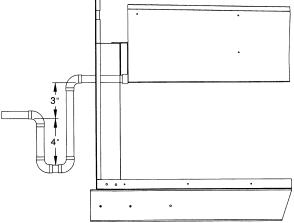
Fig. 10 Ð Condensate Drain Connections (Typical Roof Curb or Slab Mount Shown)
Step 6 Ð Controls Options Ð The control options that the units can provide are based on the following parameters: CV (constant volume) or VAV (variable air volume) operation; stand-alone unit with ®eld-supplied sensors installed (CV or VAV); as a system via the Carrier Comfort System (TEMP or VVT); optional electronic expansion board installed (CV or VAV); linked to the Carrier Comfort Network; and availability of a computer and software (Comfort Works, Building Supervisor, and Service Tool) to access the base control board. See Table 3.
NOTE: Access to the base control board allows unit occupancy schedules, unit timeclock, and various set points to be changed from their factory-de®ned default settings.
CONSTANT VOLUME APPLICATIONS Ð The standard CV unit is capable of being operated with either a Carrierapproved thermostat or a ®eld-supplied sensor. (See Price Pages for ordering information.)
Features with Thermostat Control of Unit
·two-stage heating (if installed)
·two-stage cooling
·control of unit using Y1, Y2, W1, W2, and G thermostat inputs
·control of the indoor fan
·outdoor air temperature/supply air temperature monitoring
·control of an outdoor air condenser fan based on outdoor air temperature
·control of modulating economizer damper to provide free cooling when outdoor conditions are suitable, using supply air temperature as a control point
·control of the economizer damper and indoor fan to obtain unoccupied free cooling
·provide power exhaust output to an external power exhaust controller
·support a ®eld test for ®eld checkout
·control of 2 stages of CV power exhaust
·compressor Time Guardt (power up and minimum off and on times)
Additional features are provided by accessing the standard unit control board via software with a computer. These features are:
·electronic expansion board features (if installed)
·compressor lockout during low supply air temperature
·control board diagnostics
·ability to change supply air set point (economizer control)
·ability to change high outdoor air temperature lockout set point (economizer control)
·ability to change power exhaust set points
NOTE: A CV unit without a thermostat requires a ®eldsupplied sensor for operation.
Features with Sensor Control of Unit (Stand-Alone Applications Ð Unit control is limited to CV unoccupied default set points, 90 F for cooling, 55 F for heating. There are 3 sensor options available:
·T-57 sensor will monitor room temperature
·T-55 sensor will monitor room temperature and provide unoccupied override capability (1 hour)
·T-56 sensor will monitor room temperature, provide unoccupied override capability (1 hour), and provide a temperature offset of 5° F.
Standard features are:
·support of remote occupied/unoccupied input to start and stop the unit
·cooling capacity control of 3 stages using economizer and 2 compressors to maintain space temperature to an occupied or unoccupied set point
·enable heating (if installed) or cooling during unoccupied periods as required to maintain space temperature within the unoccupied set points
·adjustment of space temperature set points of ± 5° F when using a T-56 sensor
Table 3 Ð Controls Options and Con®gurations (Non-Thermostat Applications)
UNIT CONFIGURATION |
DEFAULT COOLING |
DEFAULT HEATING |
|||
UNITS RUNNING VERSION 1.0 UNIT CONTROL SOFTWARE |
|
|
|
||
CV or VAV Unit with SPT Sensor |
Unoccupied Cooling Ð 90 F (SPT) |
Unoccupied Heating Ð 55 F (SPT) |
|||
Occupied Cooling |
Ð NA |
Occupied Heating |
Ð NA |
||
|
|||||
CV Unit with SPT Sensor and Remote |
Unoccupied Cooling Ð 90 F (SPT) |
Unoccupied Heating Ð 55 F (SPT) |
|||
Start/Stop Switch |
Occupied Cooling |
Ð 78 F (SPT) |
Occupied Heating |
Ð 68 F (SPT) |
|
VAV Unit Remote Start/Switch Only |
Unoccupied Cooling Ð NA |
Unoccupied Heating Ð NA |
|||
Occupied Cooling |
Ð 55 F (SAT) |
Occupied Heating |
Ð NA |
||
|
|||||
VAV Unit with SPT Sensor and Remote |
Unoccupied Cooling Ð 90 F (SPT) |
Unoccupied Heating Ð 55 F (SPT) |
|||
Start/Stop Switch |
Occupied Cooling |
Ð 55 F (SAT) |
Occupied Heating |
Ð NA |
|
UNITS RUNNING VERSION 2.0 UNIT CONTROL SOFTWARE |
|
|
|
||
CV or VAV Unit with SPT Sensor |
Unoccupied Cooling Ð 90 F (SPT) |
Unoccupied Heating Ð 55 F (SPT) |
|||
Occupied Cooling |
Ð NA |
Occupied Heating |
Ð NA |
||
|
|||||
CV Unit with SPT Sensor and Remote |
Unoccupied Cooling Ð 90 F (SPT) |
Unoccupied Heating Ð 55 F (SPT) |
|||
Start/Stop Switch |
Occupied Cooling |
Ð 78 F (SPT) |
Occupied Heating |
Ð 68 F (SPT) |
|
VAV Unit Remote Start/Stop Switch Only |
Unoccupied Cooling Ð 90 F (RAT) |
Unoccupied Heating Ð 55 F (RAT) |
|||
Occupied Cooling |
Ð 55 F (SAT) |
Occupied Heating |
Ð 68 F (RAT)* |
||
|
|||||
VAV Unit with SPT Sensor and Remote |
Unoccupied Cooling Ð 90 F (SPT) |
Unoccupied Heating Ð 55 F (SPT) |
|||
Start/Stop Switch |
Occupied Cooling |
Ð 55 F (SAT) |
Occupied Heating |
Ð 68 F (RAT)* |
|
|
|
LEGEND |
|
|
|
*With DIP Switch No. 5 con®gured to OPEN (Occupied Heat Enabled). |
|
CV |
Ð |
Constant Volume |
SAT |
Ð |
Supply-Air Temperature |
NOTE: Space temperature sensor and remote stop/switch are ®eld-supplied. |
|
NA |
Ð |
Not Available |
SPT |
Ð |
Space Temperature |
||
|
|||||||
RAT |
Ð |
Return-Air Temperature |
VAV |
Ð |
Variable Air Volume |
|
12
Features with sensor control of unit with computer access are:
·365 day timeclock with backup (supports minute, hour, day of week, date, month, and year)
·daylight savings time function
·occupancy control with 8 periods for unit operation
·holiday table containing up to 18 holiday schedules
·ability to initiate timed override from T-55 or T-56 sensors
·ability to use multiple space temperature sensors to average the space temperature
·supply air temperature reset for the supply air temperature set point
·temperature compensated start to calculate early start times before occupancy
·access to the Display, Maintenance, Con®guration, Service, and Set Point data table through network software
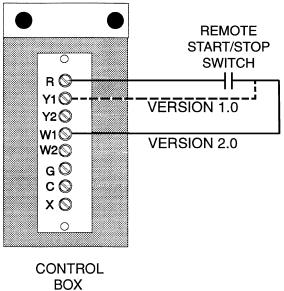
When the unit is equipped with a ®eld-supplied space temperature sensor and a remote contact closure (remote start/ stop) on the base control board, the occupied default set points will monitor unit operation. The occupied default set points are 78 F cooling and 68 F heating (if electric heat is installed). See Fig. 11 for remote start/stop wiring.
NOTE: For units which have not had the base unit control board accessed via software to set an occupancy schedule, the remote start/stop closure will allow the unit to operate in the pre-con®gured occupied default set points (based on returnair temperature) of 78 F cooling and 68 F heating. Without this feature, the unit will control to the unoccupied default set points of 90 F cooling and 55 F heating (if electric heat is installed).
An electronic expansion board may be ®eld-installed to provide the following features:
·control of modulating economizer damper to maintain indoor air quality (IAQ) when outdoor conditions are suitable
·provide discrete inputs for fan status, ®lter status, ®eldapplied status, and demand limit
·provide an output for the external alarm light indicator
When the unit is connected to the CCN (Carrier Comfort Network), the following expansion board features can be utilized.
·perform Demand Limit functions based on CCN loadshed commands or the state of the discrete input
·alarm monitoring of all key parameters
·CCN protocol
·provides power exhaust ®re outputs for direct control of modulated power exhaust stages during ®re or smoke modes
·smoke control modes including evacuation, smoke purge, pressurization, and ®re shutdown (modulating power exhaust required)
·provides CCN IAQ participation
See Carrier TEMP or VVTt (Variable Volume and Temperature) literature for complete TEMP (single zone) or VVT (multi-zone) application information.
Features with Sensor Control of Unit (Network Applications) Ð The base control board provides, as standard, a connection for use with a Carrier VVT system and can also be integrated into a Carrier Comfort Network.
When the unit is accessed via a PC equipped with Comfort Works, Building Supervisor, or Service Tool, the following features can be accessed:
·on-board timeclock can be programmed
·occupancy schedules can be programmed
·unit set points can be changed
·alarms can be monitored
This access is available on the base control board via a RJ-11 phone jack or a 3-wire connection to the communication bus. See Fig. 12. The timeclock has a 10-hour minimum back-up time to provide for unit power off for servicing unit
or during unexpected power outages. For complete Carrier Comfort System (CCS) or Carrier Comfort Network (CCN) features and bene®ts, refer to the product literature.
VARIABLE AIR VOLUME (VAV) APPLICATIONS
Features with Stand-Alone Applications Ð A VAV unit is capable of providing unoccupied cooling controlling to a 90 F return-air temperature utilizing the factory-supplied returnair thermistor located below the return-air damper in the returnair section for unit control. The unit will provide unoccupied heating (if electric heat is installed) controlling to a 55 F return-air temperature. Also provided is a morning warm-up which is initiated by the Occupied mode (if electric heat is installed) and continues until the return-air temperature rises to 68 F. The unit will provide occupied cooling with a default temperature of 55 F for the supply air. The supply-air temperature is measured by the supply-air thermistor, located in the indoor fan compartment.
Standard features of a VAV unit with a remote start/stop switch are:
·control of an outdoor condenser fan based upon outdoor air temperature
·control of modulating economizer to provide free cooling when outdoor conditions are suitable, using supply air temperature as a set point
·support of remote occupied/unoccupied input to start or stop the unit
·provide power exhaust output to an external power exhaust controller
·support supply air temperature reset to offset supply air set point
·support a ®eld test for ®eld check out
·support linkage to DAV systems
·cooling capacity control of 6 stages plus economizer with compressors and unloaders to maintain supply air temperature set point during occupied periods
·control of one stage of heat to maintain supply air temperature at supply air set point during occupied periods
·provide a variable frequency drive high voltage relay output to enable VFD
·control of heat interlock relay
With the addition of a remote start/stop switch heating or cooling is enabled during unoccupied periods as required to maintain space temperature to within unoccupied set points.
NOTE: On units running Version 1.0 of the Unit Control Software, the remote start/stop switch is connected to R and Y1. On units running Version 2.0 of the Unit Control Software, the remote start/stop switch is connected to R and W1.
Fig. 11 Ð Field Control Remote Start/Stop
13

14
|
|
LEGEND |
|
|
CCN |
Ð Carrier Comfort Network |
R |
Ð Relay |
|
COM |
Ð Common |
SIO |
Ð Serial Input/Output |
|
D |
Ð Diode |
SW |
Ð Switch |
|
N.C. |
Ð |
Normally Closed |
T |
Ð Terminal |
N.O. |
Ð |
Normally Open |
|
|
*Where X is the unit control software version (1 or 2).
Fig. 12 Ð Control Board Diagram
For units running Version 1.0 of the unit control software, network access software is required to enable occupied heating. For units running Version 2.0 of the unit control software, occupied heating is enabled or disabled by the position of DIP switch no. 5.
Additional features may be provided with electronic access to Unit Control Board. These features are:
·control board diagnostics
·compressor time guard override (power up, minimum off and on times)
·compressor lockout during low supply-air temperature
·electronic expansion board features (if installed)
·®eld test capability
·control of the economizer damper and indoor fan to option unoccupied free cooling
·365 day timeclock with backup (supports minute, hour, day, month, and year)
·holiday table containing up to 18 holiday schedules
·occupancy control with 8 periods for unit operation
·support a set of display, maintenance, con®guration, service, and set point data tables for interface with Building Supervisor, Comfort Works, or Service Tool
When a VAV unit with a space temperature sensor is accessed via a computer, the following additional features are available:
·ability to initiate timed override from T-55 sensors
·ability to use multiple space temperature sensors to average space temperature
·temperature compensated start to calculate early start time before occupancy
·provide space temperature reset to reset the supply air set point upward when the temperature falls below the occupied cooling set point
An electronic expansion board may be ®eld-installed to provide the following features:
·fan status
·®lter status
·®eld-applied status
·demand limiting
·IAQ sensor
·OAQ sensor
·alarm light
When the unit is connected to the CCN (Carrier Comfort Network), the following expansion board features can be utilized:
·CCN IAQ (indoor air quality) participation
·CCN OAQ (outdoor air quality) participation
·CCN demand limit participation
·®re unit shutdown
·®re pressurization
·®re evacuation
·®re smoke purge
·modulated power exhaust override
A ®eld-supplied space temperature sensor can be added to provide the following:
·T-57 sensor will monitor room temperature
·T-55 sensor will monitor room temperature and provide unoccupied override capability (1 hour)
When the unit is equipped with a ®eld-supplied space temperature sensor and a remote contact closure (remote start/ stop), the occupied default set points will monitor unit operation. The occupied default set points are 55 F (supply air) cooling and 68 F (space temperature) heating (if electric heat is installed). See Fig. 11 for remote start/stop wiring.
NOTE: For units without a space temperature sensor and which have not had the base unit control board accessed via software to set an occupancy schedule, the remote start/stop closure will allow the unit to operate in the pre-con®gured occupied default set points of 55 F (supply-air temperature) cooling and 68 F (return-air temperature) heating. Without
an occupancy schedule, the unit will control to the unoccupied default set points of 90 F (return air) cooling and 55 F (return air) heating (if electric heat is installed).
Features with Network Applications Ð The base control board provides, as standard, a connection for use with a Carrier Comfort System and can also be integrated into a Carrier Comfort Network. When the unit is accessed via a PC equipped with Comfort Works, Building Supervisor, or Service Tool software, the following features can be accessed:
·on-board timeclock can be programmed
·occupancy schedules can be programmed
·unit set points can be changed
·alarms can be monitored
This access is available on the base control board via a RJ-11 phone jack or a 3-wire connection to the communication bus. See Fig. 12. The timeclock has a 10-hour minimum back-up time to provide for unit power off for servicing unit or during unexpected power outages. For complete Carrier Comfort System (CCS) or Carrier Comfort Network (CCN) features and bene®ts, refer to the product literature.
Step 7 Ð Make Electrical Connections
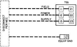
POWER WIRING Ð Units are factory wired for the voltage shown on the unit nameplate. The main terminal block is suitable for use with aluminum or copper wires and is sized for single-point electric heat.
When installing units, provide a disconnect per NEC (National Electrical Code) of adequate size (MOCP [maximum overcurrent protection] of unit is on the informative plate). All ®eld wiring must comply with NEC and all local codes. Size wire based on MCA (minimum circuit amps) on the unit informative plate. See Fig. 13 for power wiring connections to the unit power terminal block and equipment ground.
The main power terminal block is suitable for use with aluminum or copper wire. See Fig. 13. Units have circuit breakers for compressors, fan motors, and control circuit. If required by local codes, provide an additional disconnect, per NEC and local codes requirements, of adequate size (Table 4). Whenever external electrical sources are used, unit must be electrically grounded in accordance with local codes, or in absence of local codes, with NEC, ANSI (American National Standards Institute) C1-latest year.
All ®eld wiring must comply with NEC and local code requirements.
FIELD POWER SUPPLY Ð Unit is factory wired for voltage shown on nameplate. See Table 4 for electrical data.
Field wiring can be brought into the unit from bottom (through basepan and roof curb) or through side of unit (corner post next to control box).
|
|
LEGEND |
EQUIP |
Ð |
Equipment |
GND |
Ð Ground |
|
NEC |
Ð |
National Electrical Code |
TB |
Ð |
Terminal Block |
NOTE: Maximum wire size for TB1 is 500 MCM.
Fig. 13 Ð Field Power Wiring Connections
15
A 31¤2-in. NPT coupling for ®eld power wiring and a 3¤4-in. NPT coupling for 24-v control wiring are provided in basepan. In the side post, there are two 21¤2-in. (024-034) or 3-in. (038-048) knockouts for the ®eld power wiring. See Fig. 3-6. If control wiring is to be brought in through the side of unit, a 7¤8-in. diameter hole is provided in the condenser side post next to the control box.
If disconnect box is mounted to corner post, be careful not to drill any screws into the condenser coil.
Routing Through Bottom of Unit Ð If wiring is brought in through bottom of unit, use ®eld-supplied watertight conduit to run power wiring from basepan out through bottom 31¤2-in. hole to the disconnect box and back into unit to the main control box.
Use strain relief going into control box through 21¤2-in. diameter hole provided. After wires are in unit control box, connect to power terminal block (see Power Wiring section on this page 15).
Low-voltage wiring must be run in watertight conduit from the basepan to control box and through 7¤8-in. diameter hole provided in bottom of unit control box. Field-supplied strain relief must be used going into the box. After wiring is in control box, make connections to proper terminals on terminal blocks (see Field Control Wiring section on this page).
Install conduit connector in unit basepan or side panel openings provided. Route power and ground lines through connector to connections in unit control box as shown on unit wiring diagram and Fig. 13.
Routing Through Side of Unit Ð Route power wiring in ®eld-supplied watertight conduit into unit through 21¤2- or 3-in. hole. Strain relief (®eld supplied) must be used in hole. See Fig. 13.
Use ®eld-supplied strain relief going into control box through 21¤2- or 3-in. diameter hole provided. After wires are in unit control box, connect to power terminal block (see Power Wiring section on page 15).
Bring low-voltage control wiring through factory-drilled 7¤8-in. diameter hole in condenser side post. Use strain relief going into 7¤8-in. diameter hole in bottom of unit control box.
After wiring is in control box, make connection to proper terminals on terminal blocks (see Field Control Wiring section on this page).
IMPORTANT: THE VAV (variable air volume) units incorporate VFD (variable frequency drives) which generate, use, and can radiate radio frequency energy. If units are not installed and used in accordance with these instructions, they may cause radio interference. They have been tested and found to comply with limits of a Class A computing device as de®ned by FCC (Federal Communications Commission) regulations, Subpart J of Part 15, which are designed to provide reasonable protection against such interference when operated in a commercial environment.
The unit must be electrically grounded in accordance with local codes and NEC ANSI/NFPA 70 (National Fire Protection Association).
Operating voltage to compressor must be within voltage range indicated on unit nameplate. On 3-phase units, voltages between phases must be balanced within 2% and the current must be balanced within 10%.
Use the formula in Table 4 to determine the percentage of voltage imbalance.
IMPORTANT: If the supply voltage phase imbalance is more than 2%, contact your local electric utility company immediately.
Unit failure as a result of operation on improper line voltage or excessive phase imbalance constitutes abuse and may cause damage to electrical components.
On 208/230-v units, transformer no. 1 is wired for 230-v. If 208/230-v unit is to be run with 208-v power supply, the transformer must be rewired as follows:
1.Remove cap from red (208-v) wire.
2.Remove cap from spliced orange (230-v) wire. Disconnect orange wire from black unit power wire.
3.Cap orange wire.
4.Splice red wire and black unit power wire. Cap wires.
IMPORTANT: Be certain unused wires are capped. Failure to do so may damage the transformers.
FIELD CONTROL WIRING Ð Install either a Carrierapproved accessory thermostat or a CCN (Carrier Comfort Network) compatible temperature sensor. Thermostats are used on CV (constant volume) units only. Control box diagrams are shown in Fig. 14 and 15.
Thermostat Wiring (CV Only) Ð Install a Carrier-approved accessory thermostat assembly (per current price pages) according to the installation instructions included with the accessory or these instructions. Locate thermostat assembly on a solid wall in the conditioned space to sense average temperature.
Route thermostat cable or equivalent single leads of colored wire from subbase terminals to low-voltage connections as shown on unit label wiring diagram and in Fig. 16.
NOTE: For wire runs up to 50 ft, use no. 18 AWG (American Wire Gage) insulated wire (35 C minimum). For 50 to 75 ft, use no. 16 AWG insulated wire (35 C minimum). For over 75 ft, use no. 14 AWG insulated wire (35 C minimum). All wire larger than no. 18 AWG cannot be directly connected to the thermostat and will require a junction box and splice at the thermostat.
Set heat anticipators settings to 0.1 for all voltages. Settings may be changed slightly to provide a greater degree of comfort for a particular installation.
Sensor Wiring (CV or VAV) Ð The temperature sensor is wired into the unit control board. See Fig. 17.
The unit is controlled with a T55, T56 (CV only), or T57 zone sensor. Terminal TH on the sensor is connected to T1 of the base module board. Terminal COM on the sensor is connected to T2 on the base module board. If a T56 set point override sensor is used, the override connection SW on the sensor is connected to T3 on the base module board.
VAV units using Version 1.0 of the unit control software may operate without a space temperature sensor during occupied schedules, but unit will not provide unoccupied heating or cooling.
VAV Units Ð VAV units require a ®eld-supplied heat interlock relay (HIR) to drive the air terminal wide open when in heat mode. The HIR part number is HN61KK041.
Remote Field Control (Units Running Version 1.0 of Unit Control Software) Ð A switch closure across terminals R
and Y1 on TB-3 will initiate the Occupied mode. This can be done manually as well as through a ®eld-supplied timeclock.
16
Table 4 Ð Electrical Data Ð 50EJ,EK,EW,EY024-048
UNIT |
NOMINAL |
VOLTAGE |
|
COMPRESSOR |
|
|
OFM |
|
IFM |
POWER |
ELECTRIC |
|
POWER SUPPLY |
||||||||||
|
|
|
|
|
|
|
|
||||||||||||||||
VOLTAGE |
RANGE |
No. 1 |
No. 2 |
|
|
|
|
|
|
EXHAUST |
|
HEAT* |
|
|
|
|
|
||||||
SIZE |
(3 Ph 60 Hz) |
|
|
|
|
|
|
|
|
|
|
|
|
|
|
|
|
|
|
|
|
|
|
|
|
Min |
Max |
RLA |
LRA |
RLA |
|
LRA |
Qty |
Hp |
FLA (ea) |
Hp |
|
FLA |
FLA |
LRA |
kW |
FLA |
MCA |
|
|
MOCP² |
|
|
|
|
|
|
|
|
|
|
|
|
|
|
|
|
Ð |
Ð |
Ð |
Ð |
|
101.8/100.3 |
125/125 |
||
|
|
|
|
|
|
|
|
|
|
|
|
|
|
|
23.6 |
41.6 |
Ð |
Ð |
|
125.4/123.9 |
|
150/150 |
|
|
|
|
|
|
|
|
|
|
|
|
|
5 |
|
16.7/ |
Ð |
Ð |
29/36 |
75.1/ 86.6 |
114.7/127.3 |
|
125/150 |
||
|
|
|
|
|
|
|
|
|
|
|
|
|
15.2 |
23.6 |
41.6 |
29/36 |
75.1/ |
86.6 |
144.2/156.8 |
150/175 |
|||
|
|
|
|
|
|
|
|
|
|
|
|
|
|
||||||||||
|
|
|
|
|
|
|
|
|
|
|
|
|
|
|
Ð |
Ð |
59/72 |
150.1/173.2 |
171.0/192.2 |
|
200/225 |
||
|
|
|
|
|
|
|
|
|
|
|
|
|
|
|
23.6 |
41.6 |
59/72 |
150.1/173.2 |
200.5/221.7 |
225/225 |
|||
|
|
|
|
|
|
|
|
|
|
|
|
|
|
|
Ð |
Ð |
Ð |
Ð |
|
115.9/113.1 |
150/150 |
||
|
|
|
|
|
|
|
|
|
|
|
|
|
|
|
23.6 |
41.6 |
Ð |
Ð |
|
139.5/136.7 |
|
175/175 |
|
|
208/230 |
187 |
254 |
39.1 |
228 |
25.6 |
|
160 |
2 |
1 |
5.3 |
10 |
|
30.8/ |
Ð |
Ð |
29/36 |
75.1/ 86.6 |
132.3/143.3 |
|
150/150 |
||
|
|
|
28.0 |
23.6 |
41.6 |
29/36 |
75.1/ |
86.6 |
161.8/172.8 |
175/175 |
|||||||||||||
|
|
|
|
|
|
|
|
|
|
|
|
|
|
||||||||||
|
|
|
|
|
|
|
|
|
|
|
|
|
|
|
Ð |
Ð |
59/72 |
150.1/173.2 |
188.6/208.2 |
|
220/225 |
||
|
|
|
|
|
|
|
|
|
|
|
|
|
|
|
23.6 |
41.6 |
59/72 |
150.1/173.2 |
218.1/237.7 |
250/250 |
|||
|
|
|
|
|
|
|
|
|
|
|
|
|
|
|
Ð |
Ð |
Ð |
Ð |
|
131.3/127.1 |
150/150 |
||
|
|
|
|
|
|
|
|
|
|
|
|
|
|
|
23.6 |
41.6 |
Ð |
Ð |
|
154.9/150.7 |
|
175/175 |
|
|
|
|
|
|
|
|
|
|
|
|
|
15 |
|
46.2/ |
Ð |
Ð |
29/36 |
75.1/ 86.6 |
151.6/160.8 |
|
175/175 |
||
|
|
|
|
|
|
|
|
|
|
|
|
|
42.0 |
23.6 |
41.6 |
29/36 |
75.1/ |
86.6 |
181.1/190.3 |
200/200 |
|||
|
|
|
|
|
|
|
|
|
|
|
|
|
|
||||||||||
|
|
|
|
|
|
|
|
|
|
|
|
|
|
|
Ð |
Ð |
59/72 |
150.1/173.2 |
207.9/225.7 |
|
250/250 |
||
|
|
|
|
|
|
|
|
|
|
|
|
|
|
|
23.6 |
41.6 |
59/72 |
150.1/173.2 |
237.4/255.2 |
275/275 |
|||
|
|
|
|
|
|
|
|
|
|
|
|
|
|
|
Ð |
Ð |
Ð |
Ð |
|
49.4 |
|
60 |
|
|
|
|
|
|
|
|
|
|
|
|
|
|
|
|
12.6 |
23.6 |
Ð |
Ð |
|
62.0 |
|
80 |
|
|
|
|
|
|
|
|
|
|
|
|
|
5 |
|
7.6 |
Ð |
Ð |
36 |
43.3 |
|
63.6 |
|
70 |
|
|
|
|
|
|
|
|
|
|
|
|
|
|
12.6 |
23.6 |
36 |
43.3 |
79.4 |
|
80 |
||||
|
|
|
|
|
|
|
|
|
|
|
|
|
|
|
|
||||||||
|
|
|
|
|
|
|
|
|
|
|
|
|
|
|
Ð |
Ð |
72 |
86.6 |
|
96.1 |
|
110 |
|
|
|
|
|
|
|
|
|
|
|
|
|
|
|
|
12.6 |
23.6 |
72 |
86.6 |
111.9 |
|
125 |
||
|
|
|
|
|
|
|
|
|
|
|
|
|
|
|
Ð |
Ð |
Ð |
Ð |
|
55.8 |
|
70 |
|
|
|
|
|
|
|
|
|
|
|
|
|
|
|
|
12.6 |
23.6 |
Ð |
Ð |
|
68.4 |
|
80 |
|
024 |
460 |
414 |
508 |
19.9 |
114 |
11.5 |
|
80 |
2 |
1 |
2.7 |
10 |
|
14 |
Ð |
Ð |
36 |
43.3 |
|
71.6 |
|
80 |
|
|
|
12.6 |
23.6 |
36 |
43.3 |
87.4 |
|
90 |
|||||||||||||||
|
|
|
|
|
|
|
|
|
|
|
|
|
|
|
|
||||||||
|
|
|
|
|
|
|
|
|
|
|
|
|
|
|
Ð |
Ð |
72 |
86.6 |
|
104.1 |
|
110 |
|
|
|
|
|
|
|
|
|
|
|
|
|
|
|
|
12.6 |
23.6 |
72 |
86.6 |
119.9 |
|
125 |
||
|
|
|
|
|
|
|
|
|
|
|
|
|
|
|
Ð |
Ð |
Ð |
Ð |
|
62.8 |
|
80 |
|
|
|
|
|
|
|
|
|
|
|
|
|
|
|
|
12.6 |
23.6 |
Ð |
Ð |
|
75.4 |
|
90 |
|
|
|
|
|
|
|
|
|
|
|
|
|
15 |
|
21 |
Ð |
Ð |
36 |
43.3 |
|
80.4 |
|
90 |
|
|
|
|
|
|
|
|
|
|
|
|
|
|
12.6 |
23.6 |
36 |
43.3 |
96.1 |
|
100 |
||||
|
|
|
|
|
|
|
|
|
|
|
|
|
|
|
|
||||||||
|
|
|
|
|
|
|
|
|
|
|
|
|
|
|
Ð |
Ð |
72 |
86.6 |
|
112.9 |
|
125 |
|
|
|
|
|
|
|
|
|
|
|
|
|
|
|
|
12.6 |
23.6 |
72 |
86.6 |
128.6 |
|
150 |
||
|
|
|
|
|
|
|
|
|
|
|
|
|
|
|
Ð |
Ð |
Ð |
Ð |
|
40.5 |
|
50 |
|
|
|
|
|
|
|
|
|
|
|
|
|
|
|
|
12.6 |
23.6 |
Ð |
Ð |
|
53.1 |
|
60 |
|
|
|
|
|
|
|
|
|
|
|
|
|
5 |
|
6.1 |
Ð |
Ð |
36 |
34.6 |
|
50.9 |
|
60 |
|
|
|
|
|
|
|
|
|
|
|
|
|
|
12.6 |
23.6 |
36 |
34.6 |
66.7 |
|
70 |
||||
|
|
|
|
|
|
|
|
|
|
|
|
|
|
|
|
||||||||
|
|
|
|
|
|
|
|
|
|
|
|
|
|
|
Ð |
Ð |
72 |
69.3 |
|
76.9 |
|
80 |
|
|
|
|
|
|
|
|
|
|
|
|
|
|
|
|
12.6 |
23.6 |
72 |
69.3 |
92.7 |
|
100 |
||
|
|
|
|
|
|
|
|
|
|
|
|
|
|
|
Ð |
Ð |
Ð |
Ð |
|
45.4 |
|
60 |
|
|
|
|
|
|
|
|
|
|
|
|
|
|
|
|
12.6 |
23.6 |
Ð |
Ð |
|
58.0 |
|
70 |
|
|
575 |
518 |
632 |
16.0 |
91 |
9.6 |
|
64 |
2 |
1 |
2.4 |
10 |
|
11 |
Ð |
Ð |
36 |
34.6 |
|
57.1 |
|
60 |
|
|
|
|
12.6 |
23.6 |
36 |
34.6 |
72.8 |
|
80 |
||||||||||||||
|
|
|
|
|
|
|
|
|
|
|
|
|
|
|
|
||||||||
|
|
|
|
|
|
|
|
|
|
|
|
|
|
|
Ð |
Ð |
72 |
69.3 |
|
83.0 |
|
90 |
|
|
|
|
|
|
|
|
|
|
|
|
|
|
|
|
12.6 |
23.6 |
72 |
69.3 |
98.8 |
|
100 |
||
|
|
|
|
|
|
|
|
|
|
|
|
|
|
|
Ð |
Ð |
Ð |
Ð |
|
51.4 |
|
60 |
|
|
|
|
|
|
|
|
|
|
|
|
|
|
|
|
12.6 |
23.6 |
Ð |
Ð |
|
64.0 |
|
80 |
|
|
|
|
|
|
|
|
|
|
|
|
|
15 |
|
17 |
Ð |
Ð |
36 |
34.6 |
|
64.6 |
|
70 |
|
|
|
|
|
|
|
|
|
|
|
|
|
|
12.6 |
23.6 |
36 |
34.6 |
80.3 |
|
90 |
||||
|
|
|
|
|
|
|
|
|
|
|
|
|
|
|
|
||||||||
|
|
|
|
|
|
|
|
|
|
|
|
|
|
|
Ð |
Ð |
72 |
69.3 |
|
90.5 |
|
100 |
|
|
|
|
|
|
|
|
|
|
|
|
|
|
|
|
12.6 |
23.6 |
72 |
69.3 |
106.3 |
|
110 |
||
|
|
LEGEND |
FLA |
Ð |
Full Load Amps |
HACR |
Ð Heating, Air Conditioning and Refrigeration |
|
IFM |
Ð Indoor (Evaporator) Fan Motor |
|
LRA |
Ð |
Locked Rotor Amps |
MCA |
Ð |
Minimum Circuit Amps |
MOCP |
Ð |
Maximum Overcurrent Protection |
NEC |
Ð |
National Electrical Code |
OFM |
Ð Outdoor (Condenser) Fan Motor |
|
RLA |
Ð |
Rated Load Amps |
*Heater capacity (kW) is based on heater voltage of 208 v, 240 v, 480 v, and 575 v. If power distribution voltage to unit varies from rated heater voltage, heater kW will vary accordingly.
²Fuse or HACR circuit breaker.
NOTES:
1.In compliance with NEC requirements for multimotor and combination load equipment (refer to NEC Articles 430 and 440), the overcurrent protective device for the unit shall be fuse or HACR breaker. The Canadian units may be fuse or circuit breaker.
2.Unbalanced 3-Phase Supply Voltage
Never operate a motor where a phase imbalance in supply voltage is greater than 2%. Use the following formula to determine the percent of voltage imbalance.
max voltage deviation from average voltage
% Voltage Imbalance = 100 x |
|
|
|
|
|
|
|
|
average voltage |
||||
|
|
|
||||
EXAMPLE: Supply voltage is 460-3-60. |
|
|
|
|
||
AB = 452 v |
|
|
|
|
||
BC = 464 v |
|
|
|
|
||
AC = 455 v |
452 + 464 + 455 |
|||||
Average Voltage = |
||||||
|
|
|
|
|||
3 |
|
|||||
|
|
|
||||
= |
1371 |
|
||||
|
|
|
|
|||
3 |
|
|
||||
|
|
|
|
|||
= 457 |
|
|
||||
Determine maximum deviation from average voltage.
(AB) 457 − 452 = 5 v (BC) 464 − 457 = 7 v (AC) 457 − 455 = 2 v
Maximum deviation is 7 v.
Determine percent of voltage imbalance.
7
% Voltage Imbalance = 100 x
457
= 1.53%
This amount of phase imbalance is satisfactory as it is below the maximum allowable 2%.
IMPORTANT: If the supply voltage phase imbalance is more than 2%, contact your local electric utility company immediately.
3.MCA calculation for units with electric heaters over 50 kW = (1.25 x IFM amps) + (1.00 x heater FLA).
17
 Loading...