


48SS018-060 48SX024-060 Single Package Gas Heating/
Electric Cooling Units
Installation, Start-Up and
Service Instructions
CONTENTS
Page
SAFETY CONSIDERATIONS . . . . . . . . . . . . . . . . . 1-9
General . . . . . . . . . . . . . . . . . . . . . . . . . . . . . . . . . . . . . . 1
RECEIVING AND INSTALLATION . . . . . . . . . . . 10-22
Step 1 Ð Check Equipment . . . . . . . . . . . . . . . . . . 10
·IDENTIFY UNIT
·INSPECT SHIPMENT
Step 2 Ð Provide Unit Support . . . . . . . . . . . . . . 10
·ROOF CURB
·SLAB MOUNT
·FLUSH MOUNT
Step 3 Ð Field Fabricate Ductwork . . . . . . . . . . . 10 Step 4 Ð Provide Clearances . . . . . . . . . . . . . . . . 10 Step 5 Ð Rig and Place Unit . . . . . . . . . . . . . . . . . 10
·UNITS WITHOUT BASE RAIL
·UNITS WITH OPTIONAL BASE RAIL
Step 6 Ð Connect Condensate Drain . . . . . . . . . 13 Step 7 Ð Install Flue Hood . . . . . . . . . . . . . . . . . . 13 Step 8 Ð Install Gas Piping . . . . . . . . . . . . . . . . . . 13 Step 9 Ð Install Duct Connections . . . . . . . . . . . 16
·CONFIGURING UNITS FOR DOWNFLOW (VERTICAL) DISCHARGE
Step 10 Ð Install Electrical Connections . . . . . 18
·HIGH-VOLTAGE CONNECTIONS
·SPECIAL PROCEDURES FOR 208-V OPERATION
·CONTROL VOLTAGE CONNECTIONS; NON-INTEGRATED CONTROL MOTOR (NON-ICM) UNITS
·CONTROL VOLTAGE CONNECTIONS; INTEGRATED CONTROL MOTOR (ICM) UNITS
·HEAT ANTICIPATOR SETTING
·TRANSFORMER PROTECTION
PRE-START-UP . . . . . . . . . . . . . . . . . . . . . . . . . . . . 22,23 START-UP . . . . . . . . . . . . . . . . . . . . . . . . . . . . . . . . 23-44 MAINTENANCE . . . . . . . . . . . . . . . . . . . . . . . . . . . . 44-47 TROUBLESHOOTING . . . . . . . . . . . . . . . . . . . . . . 48-50 START-UP CHECKLIST . . . . . . . . . . . . . . . . . . . . . CL-1
NOTE TO INSTALLER Ð Before the installation, READ THESE INSTRUCTIONS CAREFULLY AND COMPLETELY. Also, make sure the User's Manual and Replacement Guide are left with the unit after installation. The furnace is NOT to be used for temporary heating of buildings or structures under construction.
SAFETY CONSIDERATIONS
Installation and servicing of air-conditioning equipment can be hazardous due to system pressure and electrical components. Only trained and quali®ed personnel should install, repair, or service air-conditioning equipment.
Fig. 1 Ð Unit 48SX Shown With Optional Base Rail
Untrained personnel can perform basic maintenance functions of cleaning coils and ®lters. All other operations should be performed by trained service personnel. When working on air-conditioning equipment, observe precautions in the literature, tags and labels attached to the unit, and other safety precautions that may apply.
Follow all safety codes. Wear safety glasses and work gloves. Use quenching cloth for unbrazing operations. Have ®re extinguisher available for all brazing operations.
Improper installation, adjustment, alteration, service, maintenance, or use can cause carbon monoxide poisoning, ®re, or an explosion which can result in personal injury or unit damage. Consult a quali®ed installer, service agency, or gas supplier for information or assistance. The quali- ®ed installer or agency must use only factory-authorized kits or accessories when modifying this product.
Before performing service or maintenance operations on unit, turn off gas supply then unit main power switch. Electrical shock could cause personal injury.
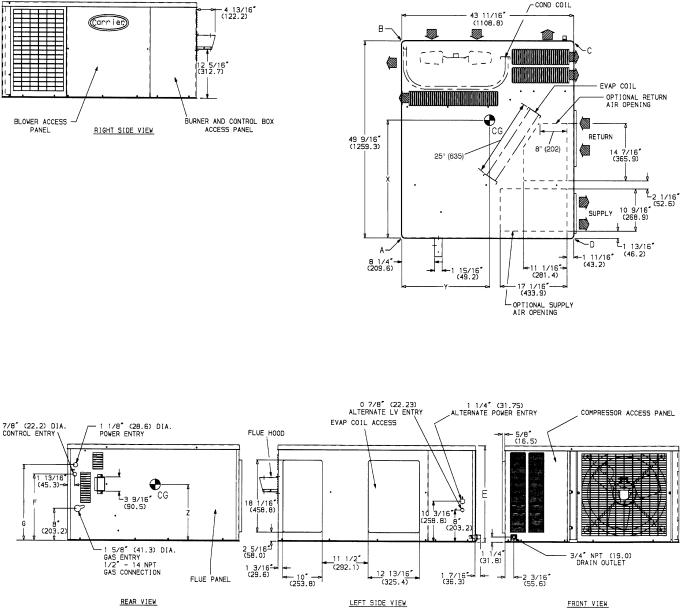
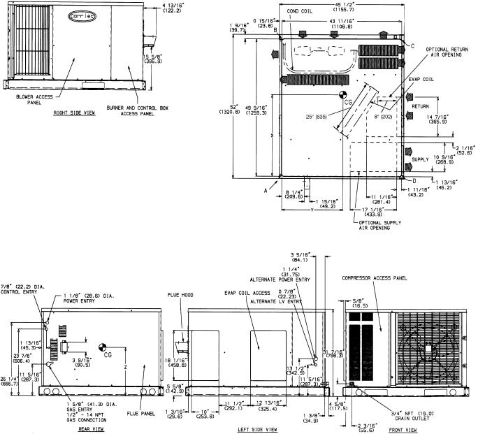
General Ð The 48SS,SX units (see Fig. 1) are fully selfcontained, combination Category I gas heating/electric cooling units designed for outdoor installation. See Fig. 2-9 (pages 2-9) for unit dimensions. All unit sizes have discharge openings for both horizontal and down¯ow con®gurations, and are factory shipped with all 4 duct openings covered. Units may be installed either on a rooftop or a ground-level cement slab. See Fig. 10 for roof curb dimensions.
Manufacturer reserves the right to discontinue, or change at any time, speci®cations or designs without notice and without incurring obligations.
Book |
1 |
4 |
|
PC 111 |
Catalog No. 534-721 |
Printed in U.S.A. |
Form 48SS,SX-12SI |
Pg 1 |
9-98 |
Replaces: 48SS,SX-11SI |
Tab |
1a |
6a |
|
|
|
|
|
|
|
|
|
|
|
|
|
|
|
|
|
|
|
REQ'D CLEARANCES FOR SERVICING. in. (mm)
Duct panel . . . . . . . . . . . . . . . . . . . . . . . . . . . . . 0
Unit top . . . . . . . . . . . . . . . . . . . . . . . . . . . 36 (914)
Side opposite ducts . . . . . . . . . . . . . . . . . . |
. . |
. 36 |
(914) |
Compressor access . . . . . . . . . . . . . . . . . . |
. . |
. 36 |
(914) |
(Except for NEC requirements) |
|
|
|
REQ'D CLEARANCES TO COMBUSTIBLE MAT'L. in. (mm) |
|
|
|
Maximum extension of overhangs . . . . . . . . . . . . . . . 48 (1219)
Unit top . . . . . . . . . . . . . . . . . . . . . . . . . . . 14 (356)
Duct side of unit . . . . . . . . . . . . . . . . . . . . . . . . 2 (51)
Side opposite ducts . . . . . . . . . . . . . . . . . . . |
. |
. 14 (356) |
Bottom of unit . . . . . . . . . . . . . . . . . . . . . . |
. . . . . 0 |
|
Flue panel . . . . . . . . . . . . . . . . . . . . . . . |
. |
. 36 (914) |
NEC REQ'D CLEARANCES. in. (mm) |
|
|
Between units, control box side . . . . . . . . . . . . . . . |
|
. 42 (1067) |
Unit and ungrounded surfaces, control box side . . . . . . . |
. |
. 36 (914) |
Unit and block or concrete walls and other grounded |
|
|
surfaces, control box side . . . . . . . . . . . . . . . . . |
|
. 42 (1067) |
|
ELECTRICAL |
UNIT WEIGHT |
|
CORNER WEIGHT |
|
UNIT HEIGHT |
||
UNIT |
|
(lb/kg) |
|
(in./mm) |
||||
CHARACTERISTICS |
|
|
|
|
||||
|
|
lb |
kg |
A |
B |
C |
D |
E |
48SS180040 |
208/230-1-60 |
272 |
123 |
81/37 |
62/28 |
76/35 |
53/24 |
24.1/613 |
48SS024040 |
208/230-1-60 |
303 |
138 |
97/44 |
43/20 |
123/56 |
40/18 |
24.1/613 |
48SS024060 |
208/230-1-60 |
315 |
143 |
100/45 |
46/21 |
126/57 |
43/20 |
24.1/613 |
48SS030040 |
208/230-1-60, 208/230-3-60 |
320 |
145 |
100/45 |
47/21 |
126/57 |
47/21 |
24.1/613 |
48SS030060/080 |
208/230-1-60, 208/230-3-60 |
332 |
149 |
103/46 |
50/22 |
129/58 |
50/23 |
24.1/613 |
48SS036060/080 |
208/230-1-60, 208/230-3-60, 460-3-60 |
336 |
153 |
86/39 |
76/35 |
111/50 |
63/29 |
24.1/613 |
48SS036100/120 |
208/230-1-60, 208/230-3-60, 460-3-60 |
348 |
158 |
89/40 |
79/36 |
114/52 |
66/30 |
24.1/613 |
48SS042060/080 |
208/230-1-60, 208/230-3-60, 460-3-60 |
375 |
170 |
95/43 |
86/39 |
119/54 |
75/34 |
28.1/714 |
48SS042100/120 |
208/230-1-60, 208/230-3-60, 460-3-60 |
387 |
176 |
98/45 |
89/40 |
122/55 |
78/35 |
28.1/714 |
|
|
|
|
|
|
|
|
|
UNIT |
F |
G |
CENTER OF GRAVITY in./mm |
|||
|
in./mm |
in./mm |
X |
Y |
Z |
|
48SS018040 |
|
|
25.07/637 |
20.59/523 |
|
|
48SS024040 |
|
|
27.07/688 |
23.35/593 |
|
|
48SS024060 |
|
|
26.98/685 |
23.27/591 |
|
|
48SS030040 |
169¤16/420.7 |
1815¤16/481.0 |
26.71/678 |
23.46/596 |
10.85/276 |
|
48SS030060/080 |
|
|
27.15/689 |
22.36/568 |
|
|
48SS036060/080 |
|
|
27.50/698 |
22.48/571 |
|
|
48SS036100/120 |
|
|
27.40/696 |
22.44/570 |
|
|
48SS042060/080 |
209¤16/522.3 |
2215¤16/582.6 |
27.01/686 |
22.44/570 |
12.7/321 |
|
48SS042100/120 |
26.94/684 |
22.44/570 |
||||
|
|
|
||||
|
|
|
|
|
|
|
|
|
LEGEND |
|
|
|
CG |
Ð |
Center of Gravity |
MAT'L |
Ð |
Material |
COND |
Ð Condenser |
NEC |
Ð National Electrical Code |
||
LV |
Ð |
Low Voltage |
REQ'D |
Ð |
Required |
NOTES:
1.Clearances must be maintained to prevent recirculation of air from outdoorfan discharge.
2.Adequate clearance around air openings into combustion chamber must be provided.
Fig. 2 Ð 48SS018-042 Without Base Rail, Unit Dimensions
2
REQ'D CLEARANCES FOR SERVICING. in. (mm)
Duct panel . . . . . . . . . . . . . . . . . . . . . . . . . . . . . 0
Unit top . . . . . . . . . . . . . . . . . . . . . . . . . . . 36 (914)
Side opposite ducts . . . . . . . . . . . . . . . . . . . |
. |
. 36 |
(914) |
Compressor access . . . . . . . . . . . . . . . . . . . |
. |
. 36 |
(914) |
(Except for NEC requirements) |
|
|
|
REQ'D CLEARANCES TO COMBUSTIBLE MAT'L. in. (mm) |
|
|
|
Maximum extension of overhangs . . . . . . . . . . . . . . . 48 (1219)
Unit top . . . . . . . . . . . . . . . . . . . . . . . . . . . 14 (356)
Duct side of unit . . . . . . . . . . . . . . . . . . . . . . . . 2 (51)
Side opposite ducts . . . . . . . . . . . . . . . |
. . . . . . 14 (356) |
|||
Bottom of unit . . . . . . . . . . . . . . . . . . |
. . |
. |
. . . . . . 0 |
|
Flue panel . . . . . . . . . . . . . . . . . . . |
. . |
. |
. . |
. 36 (914) |
NEC REQ'D CLEARANCES. in. (mm) |
|
|
|
|
Between units, control box side . . . . . . . . . . . |
. . . . . 42 (1067) |
|||
Unit and ungrounded surfaces, control box side . . . |
. . |
. |
. . |
. 36 (914) |
Unit and block or concrete walls and other grounded |
|
|
|
|
surfaces, control box side . . . . . . . . . . . . . |
. . |
. |
. |
. 42 (1067) |
|
ELECTRICAL |
UNIT WEIGHT |
|
CORNER WEIGHT |
|
UNIT HEIGHT |
||
UNIT |
|
(lb/kg) |
|
(in./mm) |
||||
CHARACTERISTICS |
|
|
|
|
||||
|
|
lb |
kg |
A |
B |
C |
D |
E |
48SS018040 |
208/230-1-60 |
296 |
135 |
87/40 |
68/31 |
82/37 |
59/27 |
27.4/697 |
48SS024040 |
208/230-1-60 |
327 |
149 |
103/47 |
49/22 |
129/59 |
46/21 |
27.4/697 |
48SS024060 |
208/230-1-60 |
339 |
155 |
106/48 |
52/24 |
132/60 |
49/22 |
27.4/697 |
48SS030040 |
208/230-1-60, 208/230-3-60 |
344 |
157 |
106/48 |
53/24 |
132/60 |
53/24 |
27.4/697 |
48SS030060/080 |
208/230-1-60, 208/230-3-60 |
356 |
162 |
102/46 |
71/32 |
123/56 |
60/27 |
27.4/697 |
48SS036060/080 |
208/230-1-60, 208/230-3-60, 460-3-60 |
360 |
164 |
92/42 |
82/37 |
117/53 |
69/31 |
27.4/697 |
48SS036100/120 |
208/230-1-60, 208/230-3-60, 460-3-60 |
372 |
169 |
95/43 |
85/39 |
120/55 |
72/33 |
27.4/697 |
48SS042060/080 |
208/230-1-60, 208/230-3-60, 460-3-60 |
399 |
181 |
101/46 |
92/42 |
125/57 |
81/37 |
31.4/798 |
48SS042100/120 |
208/230-1-60, 208/230-3-60, 460-3-60 |
411 |
187 |
104/47 |
95/43 |
128/58 |
84/38 |
31.4/798 |
|
|
|
|
|
|
|
|
|
UNIT |
F |
G |
CENTER OF GRAVITY in./mm |
||||
|
in./mm |
in./mm |
X |
|
Y |
Z |
|
48SS018040 |
|
|
25.04/636 |
22.72/577 |
|
||
48SS024040 |
|
|
26.90/683.3 |
20.17/512.3 |
|
||
48SS024060 |
|
|
26.82/681.2 |
20.22/513.6 |
|
||
48SS030040 |
197¤8/504.8 |
221¤4/565.4 |
26.57/674.9 |
20.1 |
/509.3 |
13.16/334.3 |
|
48SS030060/080 |
|
|
26.93/684 |
21.1 |
/535.4 |
|
|
48SS036060/080 |
|
|
27.31/693.7 |
21.0 |
/532.6 |
|
|
48SS036100/120 |
|
|
27.23/691.6 |
21.0 |
/533.1 |
|
|
48SS042060/080 |
237¤8/606.4 |
261¤4/666.8 |
26.87/682.5 |
21.0 |
/533.1 |
14.96/380 |
|
48SS042100/120 |
26.81/681 |
21.0 |
/533.7 |
||||
|
|
|
|||||
|
|
|
|
|
|
|
|
|
|
LEGEND |
|
|
|
CG |
Ð |
Center of Gravity |
MAT'L |
Ð |
Material |
COND |
Ð Condenser |
NEC |
Ð National Electrical Code |
||
LV |
Ð |
Low Voltage |
REQ'D |
Ð |
Required |
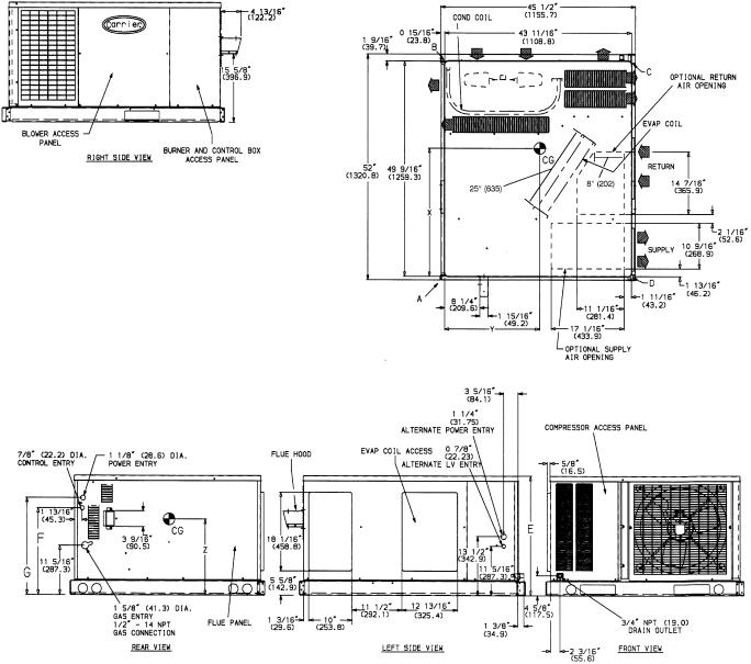
NOTES:
1.Clearances must be maintained to prevent recirculation of air from outdoorfan discharge.
2.Adequate clearance around air openings into combustion chamber must be provided.
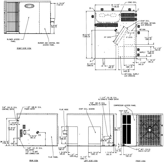
Fig. 3 Ð 48SS018-042 With Optional Base Rail, Unit Dimensions
3
REQ'D CLEARANCES FOR SERVICING. in. (mm)
Duct panel . . . . . . . . . . . . . . . . . . . . . . . . . . . . . 0
Unit top . . . . . . . . . . . . . . . . . . . . . . . . . . . 36 (914)
Side opposite ducts . . . . . . . . . . . . . . . . . . . . |
. 36 |
(914) |
Compressor access . . . . . . . . . . . . . . . . . . . . |
. 36 |
(914) |
(Except for NEC requirements) |
|
|
REQ'D CLEARANCES TO COMBUSTIBLE MAT'L. in. (mm) |
|
|
Maximum extension of overhangs . . . . . . . . . . . . . . . 48 (1219)
Unit top . . . . . . . . . . . . . . . . . . . . . . . . . . . 14 (356)
Duct side of unit . . . . . . . . . . . . . . . . . . . . . . . . 2 (51)
Side opposite ducts . . . . . . . . . . . . . . . . . . . |
. |
. 14 (356) |
Bottom of unit . . . . . . . . . . . . . . . . . . . . . . |
. . . . . 0 |
|
Flue panel . . . . . . . . . . . . . . . . . . . . . . . |
. |
. 36 (914) |
NEC REQ'D CLEARANCES. in. (mm) |
|
|
Between units, control box side . . . . . . . . . . . . . . . |
|
. 42 (1067) |
Unit and ungrounded surfaces, control box side . . . . . . . |
. |
. 36 (914) |
Unit and block or concrete walls and other grounded |
|
|
surfaces, control box side . . . . . . . . . . . . . . . . . |
|
. 42 (1067) |
|
ELECTRICAL |
UNIT WEIGHT |
|
CORNER WEIGHT |
|
|||
UNIT |
|
|
(lb/kg) |
|
||||
CHARACTERISTICS |
|
|
|
|
|
|||
|
|
lb |
kg |
A |
B |
|
C |
D |
48SS048080 |
208/230-1-60, 208/230-3-60, 460-3-60 |
414 |
188 |
107/49 |
83/38 |
|
158/72 |
66/30 |
48SS048100/120/140 |
208/230-1-60, 208/230-3-60, 460-3-60 |
426 |
193 |
110/50 |
86/39 |
|
159/72 |
71/32 |
48SS060080 |
208/230-1-60, 208/230-3-60, 460-3-60 |
453 |
206 |
117/53 |
93/42 |
|
167/76 |
76/35 |
48SS060100/120/140 |
208/230-1-60, 208/230-3-60, 460-3-60 |
465 |
211 |
120/55 |
96/44 |
|
167/76 |
82/37 |
|
|
|
|
|
|
|
|
|
UNIT |
CENTER OF GRAVITY (in./mm) |
|||
X |
Y |
Z |
||
|
||||
48SS048080 |
28.76/731 |
23.46/596 |
15.35/390 |
|
48SS048100/120/140 |
28.42/722 |
23.42/595 |
15.35/390 |
|
48SS060080 |
28.36/720 |
23.27/591 |
15.35/390 |
|
48SS060100/120/140 |
27.95/710 |
23.23/590 |
15.35/390 |
|
|
|
LEGEND |
|
|
|
CG |
Ð |
Center of Gravity |
MAT'L |
Ð |
Material |
COND |
Ð Condenser |
NEC |
Ð National Electrical Code |
||
LV |
Ð |
Low Voltage |
REQ'D |
Ð |
Required |
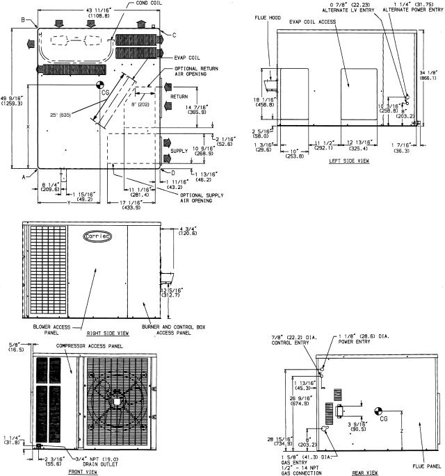
NOTES:
1.Clearances must be maintained to prevent recirculation of air from outdoorfan discharge.
2.Adequate clearance around air openings into combustion chamber must be provided.
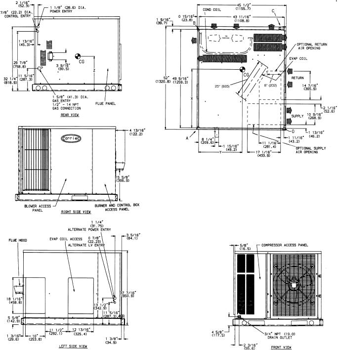
Fig. 4 Ð 48SS048,060 Without Base Rail, Unit Dimensions
4

REQ'D CLEARANCES FOR SERVICING. in. (mm)
Duct panel . . . . . . . . . . . . . . . . . . . . . . . . . . . . . 0
Unit top . . . . . . . . . . . . . . . . . . . . . . . . . . . 36 (914)
Side opposite ducts . . . . . . . . . . . . . . . . . . . |
. |
. 36 |
(914) |
Compressor access . . . . . . . . . . . . . . . . . . . |
. |
. 36 |
(914) |
(Except for NEC requirements) |
|
|
|
REQ'D CLEARANCES TO COMBUSTIBLE MAT'L. in. (mm) |
|
|
|
Maximum extension of overhangs . . . . . . . . . . . . . . . 48 (1219)
Unit top . . . . . . . . . . . . . . . . . . . . . . . . . . . 14 (356)
Duct side of unit . . . . . . . . . . . . . . . . . . . . . . . . 2 (51)
Side opposite ducts . . . . . . . . . . . . . . . . . . . |
. |
. 14 (356) |
Bottom of unit . . . . . . . . . . . . . . . . . . . . . . |
. . . . . 0 |
|
Flue panel . . . . . . . . . . . . . . . . . . . . . . . |
. |
. 36 (914) |
NEC REQ'D CLEARANCES. in. (mm) |
|
|
Between units, control box side . . . . . . . . . . . . . . . |
|
. 42 (1067) |
Unit and ungrounded surfaces, control box side . . . . . . . |
. |
. 36 (914) |
Unit and block or concrete walls and other grounded |
|
|
surfaces, control box side . . . . . . . . . . . . . . . . . |
|
. 42 (1067) |
|
ELECTRICAL |
UNIT WEIGHT |
|
CORNER WEIGHT |
|
|||
UNIT |
|
|
(lb/kg) |
|
||||
CHARACTERISTICS |
|
|
|
|
|
|||
|
|
lb |
kg |
A |
B |
|
C |
D |
48SS048080 |
208/230-1-60, 208/230-3-60, 460-3-60 |
438 |
199 |
113/51 |
89/40 |
|
164/75 |
72/33 |
48SS048100/120/140 |
208/230-1-60, 208/230-3-60, 460-3-60 |
450 |
205 |
116/53 |
92/42 |
|
165/75 |
77/35 |
48SS060080 |
208/230-1-60, 208/230-3-60, 460-3-60 |
477 |
217 |
123/56 |
99/45 |
|
173/79 |
82/37 |
48SS060100/120/140 |
208/230-1-60, 208/230-3-60, 460-3-60 |
489 |
222 |
126/57 |
102/46 |
|
173/79 |
88/40 |
|
|
|
|
|
|
|
|
|
UNIT |
CENTER OF GRAVITY (in./mm) |
|||
X |
Y |
Z |
||
|
||||
48SS048080 |
28.54/724.9 |
20.00/508 |
17.66/448.6 |
|
48SS048100/120/140 |
28.22/716.8 |
20.05/509.3 |
17.66/448.6 |
|
48SS060080 |
28.18/715.6 |
20.19/512.8 |
17.66/448.6 |
|
48SS060100/120/140 |
27.79/705.9 |
20.23/513.8 |
17.66/448.6 |
|
|
|
|
|
|
|
|
LEGEND |
|
|
|
CG |
Ð |
Center of Gravity |
MAT'L |
Ð |
Material |
COND |
Ð Condenser |
NEC |
Ð National Electrical Code |
||
LV |
Ð |
Low Voltage |
REQ'D |
Ð |
Required |
NOTES:
1.Clearances must be maintained to prevent recirculation of air from outdoorfan discharge.
2.Adequate clearance around air openings into combustion chamber must be provided.
Fig. 5 Ð 48SS048,060 With Optional Base Rail, Unit Dimensions
5
REQ'D CLEARANCES FOR SERVICING. in. (mm)
Duct panel . . . . . . . . . . . . . . . . . . . . . . . . . . . . . 0
Unit top . . . . . . . . . . . . . . . . . . . . . . . . . . . 36 (914)
Side opposite ducts . . . . . . . . . . . . . . . . . . |
. . |
. 36 |
(914) |
Compressor access . . . . . . . . . . . . . . . . . . |
. . |
. 36 |
(914) |
(Except for NEC requirements) |
|
|
|
REQ'D CLEARANCES TO COMBUSTIBLE MAT'L. in. (mm) |
|
|
|
Maximum extension of overhangs . . . . . . . . . . . . . . . 48 (1219)
Unit top . . . . . . . . . . . . . . . . . . . . . . . . . . . 14 (356)
Duct side of unit . . . . . . . . . . . . . . . . . . . . . . . . 2 (51)
Side opposite ducts . . . . . . . . . . . . . . . |
. . . . . . 14 (356) |
||
Bottom of unit . . . . . . . . . . . . . . . . . . |
. . |
. . |
. . . . . 0 |
Flue panel . . . . . . . . . . . . . . . . . . . |
. . |
. . |
. . 36 (914) |
NEC REQ'D CLEARANCES. in. (mm) |
|
|
|
Between units, control box side . . . . . . . . . . . |
. . . . . 42 (1067) |
||
Unit and ungrounded surfaces, control box side . . . |
. . |
. . |
. . 36 (914) |
Unit and block or concrete walls and other grounded |
|
|
|
surfaces, control box side . . . . . . . . . . . . . |
. . |
. . |
. 42 (1067) |
|
ELECTRICAL |
UNIT WEIGHT |
|
CORNER WEIGHT |
|
||
UNIT |
|
(lb/kg) |
|
||||
CHARACTERISTICS |
|
|
|
|
|||
|
|
lb |
kg |
A |
B |
C |
D |
48SX024040 |
208/230-1-60 |
333 |
151 |
104/47 |
50/23 |
130/59 |
49/22 |
48SX024060 |
208/230-1-60 |
345 |
157 |
107/49 |
53/24 |
133/60 |
52/24 |
48SX030040 |
208/230-1-60 |
336 |
153 |
97/44 |
66/30 |
118/54 |
55/25 |
48SX030060/080 |
208/230-1-60 |
348 |
158 |
100/45 |
69/31 |
121/55 |
58/26 |
48SX036060/080 |
208/230-1-60, 208/230-3-60, 460-3-60 |
366 |
166 |
94/43 |
84/38 |
117/53 |
71/32 |
48SX036100/120 |
208/230-1-60, 208/230-3-60, 460-3-60 |
378 |
172 |
97/44 |
87/40 |
120/55 |
74/34 |
|
|
|
|
|
|
|
|
UNIT |
CENTER OF GRAVITY (in./mm) |
|||
X |
Y |
Z |
||
|
||||
48SX024040 |
26.71/678 |
20.06/510 |
12.65/321 |
|
48SX024060 |
26.64/677 |
20.12/511 |
12.65/321 |
|
48SX030040 |
27.06/687 |
21.05/535 |
12.65/321 |
|
48SX030060/080 |
26.98/685 |
21.07/535 |
12.65/321 |
|
48SX036060/080 |
27.14/689 |
21.10/536 |
12.65/321 |
|
48SX036100/120 |
27.06/687 |
21.12/536 |
12.65/321 |
|
|
|
|
|
|
|
|
LEGEND |
|
|
|
CG |
Ð |
Center of Gravity |
MAT'L |
Ð |
Material |
COND |
Ð Condenser |
NEC |
Ð National Electrical Code |
||
LV |
Ð |
Low Voltage |
REQ'D |
Ð |
Required |
NOTES:
1.Clearances must be maintained to prevent recirculation of air from outdoorfan discharge.
2.Adequate clearance around air openings into combustion chamber must be provided.
Fig. 6 Ð 48SX024-036 Without Base Rail, Unit Dimensions
6
REQ'D CLEARANCES FOR SERVICING. in. (mm)
Duct panel . . . . . . . . . . . . . . . . . . . . . . . . . . . 0 Unit top . . . . . . . . . . . . . . . . . . . . . . . . . 36 (914) Side opposite ducts . . . . . . . . . . . . . . . . . . . . 36 (914) Compressor access . . . . . . . . . . . . . . . . . . . . 36 (914) (Except for NEC requirements)
REQ'D CLEARANCES TO COMBUSTIBLE MAT'L. in. (mm)
Maximum extension of overhangs . . . . . . . . . . . . . 48 (1219)
Unit top . . . . . . . . . . . . . . . . . . . . . . . . . 14 (356)
Duct side of unit . . . . . . . . . . . . . . . . . . . . . . 2 (51)
Side opposite ducts . . . . . . . . . . . . . . . . . . . . 14 (356)
Bottom of unit . . . . . . . . . . . . . . . . . . . . . . . . . 0
Flue panel . . . . . . . . . . . . . . . . . . . . . . . . 36 (914)
NEC REQ'D CLEARANCES. in. (mm) |
|
|
Between units, control box side . . . . . . . . . . . . . |
. 42 |
(1067) |
Unit and ungrounded surfaces, control box side . . . . . |
. . 36 (914) |
|
Unit and block or concrete walls and other grounded |
|
|
surfaces, control box side . . . . . . . . . . . . . . . |
. 42 |
(1067) |
|
ELECTRICAL |
UNIT WEIGHT |
|
CORNER WEIGHT |
|
||
UNIT |
|
(lb/kg) |
|
||||
CHARACTERISTICS |
|
|
|
|
|||
|
|
lb |
kg |
A |
B |
C |
D |
48SX024040 |
208/230-1-60 |
357 |
163 |
110/50 |
56/25 |
136/62 |
55/25 |
48SX024060 |
208/230-1-60 |
369 |
168 |
113/51 |
59/27 |
139/63 |
58/26 |
48SX030040 |
208/230-1-60 |
360 |
164 |
103/47 |
72/33 |
124/56 |
61/28 |
48SX030060/080 |
208/230-1-60 |
372 |
169 |
106/48 |
75/34 |
127/58 |
64/29 |
48SX036060/080 |
208/230-1-60, 208/230-3-60, 460-3-60 |
390 |
177 |
100/45 |
90/41 |
123/56 |
77/35 |
48SX036100/120 |
208/230-1-60, 208/230-3-60, 460-3-60 |
402 |
183 |
103/47 |
93/42 |
127/57 |
80/36 |
|
|
|
|
|
|
|
|
UNIT |
CENTER OF GRAVITY (in./mm) |
|||
X |
Y |
Z |
||
|
||||
48SX024040 |
26.57/674.9 |
20.17/512.3 |
14.96/380.0 |
|
48SX024060 |
26.51/673.3 |
20.22/513.6 |
14.96/380.0 |
|
48SX030040 |
26.90/683.3 |
21.09/535.7 |
14.96/380.0 |
|
48SX030060/080 |
26.83/681.5 |
21.11/536.2 |
14.96/380.0 |
|
48SX036060/080 |
26.99/685.5 |
21.14/537.0 |
14.96/380.0 |
|
48SX036100/120 |
26.92/683.8 |
21.14/537.0 |
14.96/380.0 |
|
|
|
LEGEND |
|
|
|
CG |
Ð |
Center of Gravity |
MAT'L |
Ð |
Material |
COND |
Ð Condenser |
NEC |
Ð National Electrical Code |
||
LV |
Ð |
Low Voltage |
REQ'D |
Ð |
Required |
NOTES:
1.Clearances must be maintained to prevent recirculation of air from outdoorfan discharge.
2.Adequate clearance around air openings into combustion chamber must be provided.
Fig. 7 Ð 48SX024-036 With Optional Base Rail, Unit Dimensions
7
REQ'D CLEARANCES FOR SERVICING. in. (mm)
Duct panel . . . . . . . . . . . . . . . . . . . . . . . . . . . . . 0
Unit top . . . . . . . . . . . . . . . . . . . . . . . . . . . 36 (914)
Side opposite ducts . . . . . . . . . . . . . . . . . . |
. . |
. 36 |
(914) |
Compressor access . . . . . . . . . . . . . . . . . . |
. . |
. 36 |
(914) |
(Except for NEC requirements) |
|
|
|
REQ'D CLEARANCES TO COMBUSTIBLE MAT'L. in. (mm) |
|
|
|
Maximum extension of overhangs . . . . . . . . . . . . . . . 48 (1219)
Unit top . . . . . . . . . . . . . . . . . . . . . . . . . . . 14 (356)
Duct side of unit . . . . . . . . . . . . . . . . . . . . . . . . 2 (51)
Side opposite ducts . . . . . . . . . . . . . . . . . . . |
. |
. 14 (356) |
Bottom of unit . . . . . . . . . . . . . . . . . . . . . . |
. . . . . 0 |
|
Flue panel . . . . . . . . . . . . . . . . . . . . . . . |
. |
. 36 (914) |
NEC REQ'D CLEARANCES. in. (mm) |
|
|
Between units, control box side . . . . . . . . . . . . . . . |
|
. 42 (1067) |
Unit and ungrounded surfaces, control box side . . . . . . . |
. |
. 36 (914) |
Unit and block or concrete walls and other grounded |
|
|
surfaces, control box side . . . . . . . . . . . . . . . . . |
|
. 42 (1067) |
|
ELECTRICAL |
UNIT WEIGHT |
|
CORNER WEIGHT |
|
||
UNIT |
|
(lb/kg) |
|
||||
CHARACTERISTICS |
|
|
|
|
|||
|
|
lb |
kg |
A |
B |
C |
D |
48SX042060/080 |
208/230-1-60, 208/230-3-60, 460-3-60 |
391 |
178 |
100/45 |
91/41 |
120/55 |
80/36 |
48SX042100/120 |
208/230-1-60, 208/230-3-60, 460-3-60 |
403 |
183 |
103/47 |
94/43 |
123/56 |
83/38 |
48SX048080 |
208/230-1-60, 208/230-3-60, 460-3-60 |
422 |
192 |
109/50 |
85/39 |
158/72 |
70/32 |
48SX048100/120/140 |
208/230-1-60, 208/230-3-60, 460-3-60 |
434 |
197 |
112/51 |
88/40 |
161/73 |
73/33 |
48SX060080 |
208/230-1-60, 208/230-3-60 |
453 |
206 |
117/53 |
93/42 |
167/76 |
76/35 |
48SX060100/120/140 |
208/230-1-60, 208/230-3-60 |
465 |
211 |
120/55 |
96/44 |
167/76 |
82/37 |
|
|
|
|
|
|
|
|
UNIT |
CENTER OF GRAVITY (in./mm) |
|||
X |
Y |
Z |
||
|
||||
48SX042060/080 |
26.66/677 |
21.19/538 |
15.35/390 |
|
48SX042100/120 |
26.61/676 |
21.21/539 |
15.35/390 |
|
48SX048080 |
28.45/723 |
19.95/507 |
15.35/390 |
|
48SX048100/120/140 |
28.35/720 |
19.99/508 |
15.35/390 |
|
48SX060080 |
28.36/720 |
23.27/591 |
15.35/390 |
|
48SX060100/120/140 |
27.95/710 |
23.23/590 |
15.35/390 |
|
|
|
|
|
|
|
|
LEGEND |
|
|
|
CG |
Ð |
Center of Gravity |
MAT'L |
Ð |
Material |
COND |
Ð Condenser |
NEC |
Ð National Electrical Code |
||
LV |
Ð |
Low Voltage |
REQ'D |
Ð |
Required |
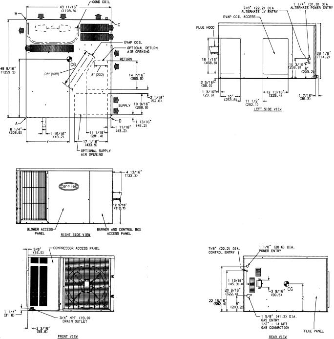
NOTES:
1.Clearances must be maintained to prevent recirculation of air from outdoorfan discharge.
2.Adequate clearance around air openings into combustion chamber must be provided.
Fig. 8 Ð 48SX042-060 Without Base Rail, Unit Dimensions
8
|
|
REQ'D CLEARANCES FOR SERVICING. in. (mm) |
|
|
|
|
|
Duct panel . . . . . . . . . . . . . . . . . . . . . . . . . . . . . 0 |
|||
|
|
Unit top . . . . . . . . . . . . . . . . . . . . . . . . . . . 36 (914) |
|||
|
|
Side opposite ducts . . . . . . . . . . . . . . . . . . |
. |
. |
. 36 (914) |
|
|
Compressor access . . . . . . . . . . . . . . . . . . |
. |
. |
. 36 (914) |
|
|
(Except for NEC requirements) |
|
|
|
|
|
REQ'D CLEARANCES TO COMBUSTIBLE MAT'L. in. (mm) |
|
|
|
|
|
Maximum extension of overhangs . . . . . . . . . . . . . . . 48 (1219) |
|||
|
|
Unit top . . . . . . . . . . . . . . . . . . . . . . . . . . . 14 (356) |
|||
|
|
Duct side of unit . . . . . . . . . . . . . . . . . . . . . . . . 2 (51) |
|||
|
|
Side opposite ducts . . . . . . . . . . . . . . . . . . |
. |
. |
. 14 (356) |
|
|
Bottom of unit . . . . . . . . . . . . . . . . . . . . . |
. . . . . . 0 |
||
|
|
Flue panel . . . . . . . . . . . . . . . . . . . . . . |
. |
. |
. 36 (914) |
|
LEGEND |
|
|
|
|
CG |
Ð Center of Gravity |
|
|
|
|
COND |
Ð Condenser |
|
|
|
|
LV |
Ð |
Low Voltage |
|
|
|
MAT'L |
Ð |
Material |
|
|
|
NEC |
Ð |
National Electrical Code |
|
|
|
REQ'D |
Ð |
Required |
|
|
|
|
ELECTRICAL |
UNIT WEIGHT |
|
CORNER WEIGHT |
|
||
UNIT |
|
(lb/kg) |
|
||||
CHARACTERISTICS |
|
|
|
|
|||
|
|
lb |
kg |
A |
B |
C |
D |
48SX042060,080 |
208/230-1-60, 208/230-3-60, 460-3-60 |
415 |
189 |
106/48 |
97/44 |
126/57 |
86/39 |
48SX042100,120 |
208/230-1-60, 208/230-3-60, 460-3-60 |
427 |
194 |
109/50 |
100/45 |
129/59 |
89/40 |
48SX048080 |
208/230-1-60, 208/230-3-60, 460-3-60 |
446 |
293 |
115/52 |
91/41 |
164/75 |
76/35 |
48SX048100/120/140 |
208/230-1-60, 208/230-3-60, 460-3-60 |
458 |
208 |
118/54 |
94/43 |
167/76 |
79/36 |
48SX060080 |
208/230-1-60, 208/230-3-60 |
477 |
217 |
123/56 |
99/45 |
173/79 |
82/37 |
48SX060100/120/140 |
208/230-1-60, 208/230-3-60 |
489 |
222 |
126/57 |
102/46 |
173/79 |
88/40 |
|
|
|
|
|
|
|
|
UNIT |
CENTER OF GRAVITY (in./mm) |
|||
X |
Y |
Z |
||
|
||||
48SX042060,080 |
26.55/674.4 |
21.22/539.0 |
17.66/448.6 |
|
48SX042100,120 |
26.50/673.0 |
21.24/539.6 |
17.66/448.6 |
|
48SX048080 |
28.25/717.6 |
20.04/509.0 |
17.66/448.6 |
|
48SX048100/120/140 |
28.16/715.3 |
20.08/510.0 |
17.66/448.6 |
|
48SX060080 |
28.18/715.6 |
20.19/512.8 |
17.66/448.6 |
|
48SX060100/120/140 |
27.79/705.9 |
20.23/513.8 |
17.66/448.6 |
|
NOTES:
1.Clearances must be maintained to prevent recirculation of air from outdoorfan discharge.
2.Adequate clearance around air openings into combustion chamber must be provided.
NEC REQ'D CLEARANCES. in. (mm) |
|
|
|
Between units, control box side . . . . . . . . . . . . . . |
. |
. 42 |
(1067) |
Unit and ungrounded surfaces, control box side . . . . . . |
. . |
. 36 (914) |
|
Unit and block or concrete walls and other grounded |
|
|
|
surfaces, control box side . . . . . . . . . . . . . . . . |
. |
. 42 |
(1067) |
Fig. 9 Ð 48SX042-060 With Optional Base Rail, Unit Dimensions
9
RECEIVING AND INSTALLATION
Step 1 Ð Check Equipment
IDENTIFY UNIT Ð The unit model number and serial number are stamped on unit identi®cation plate. Check this information against shipping papers and job data.
INSPECT SHIPMENT Ð Inspect for shipping damage while unit is still on shipping pallet. If unit appears to be damaged or is torn loose from its anchorage, have it examined by transportation inspectors before removal. Forward claim papers directly to transportation company. Manufacturer is not responsible for any damage incurred in transit.
Check all items against shipping list. Immediately notify the nearest Carrier Air Conditioning office if any item is missing.
To prevent loss or damage, leave all parts in original packages until installation.
Step 2 Ð Provide Unit Support
ROOF CURB Ð Install accessory roof curb in accordance with instructions shipped with curb. See Fig. 10 for roof curb dimensions. Install insulation, cant strips, roo®ng, and ¯ashing. Ductwork must be attached to curb.
IMPORTANT: The gasketing of the unit to the roof curb is critical for a watertight seal. Install gasketing material supplied with the roof curb. Improperly applied gasketing can also result in air leaks and poor unit performance.
Curb should be level to within 1¤4 inch. This is necessary for unit drain to function properly. Refer to accessory roof curb installation instructions for additional information as required.
SLAB MOUNT Ð Place the unit on a solid, level concrete pad that is a minimum of 4 in. thick with 2 in. above grade. The slab should be ¯ush on the front of the unit (to allow condensate drain installation) and should extend 2 in. on the three remaining sides of the unit. See Fig. 11. Install a 6-in. gravel apron in front of condenser-air inlets to prevent obstruction of air¯ow by grass or shrubs. Do not secure the unit to the slab except when required by local codes.
FLUSH MOUNT Ð Place side of unit with duct panel ¯ush against transition. On units with optional base rails, the skirt on duct-panel side of unit can be removed to allow unit to be mounted ¯ush against transitions that extend below basepan of unit. To remove skirt, remove 4 screws holding skirt to base rail. Then, remove skirt.
To remove wood support under unit (with base rail only), loosen 4 screws above rigging holes and slide assembly out through rectangular hole.
Step 3 Ð Field Fabricate Ductwork Ð Secure all ducts to roof curb and building structure on vertical discharge units. Do not connect ductwork to unit. For horizontal applications, unit is provided with ¯anges on the horizontal openings. All ductwork should be secured to the ¯anges. Insulate and weatherproof all external ductwork, joints, and roof openings with counter ¯ashing and mastic in accordance with applicable codes.
Ducts passing through an unconditioned space must be insulated and covered with a vapor barrier.
If a plenum return is used on a vertical unit, the return should be ducted through the roof deck to comply with applicable ®re codes.
A minimum clearance is not required around ductwork. Cabinet return-air static shall not exceed −.25 in. wg.
Step 4 Ð Provide Clearances Ð The required minimum operating and service clearances are shown in Fig. 2-9. Adequate combustion, ventilation, and condenser air must be provided, in accordance with section 5.3, Air for Combustion and Ventilation, of the National Fuel Gas Code ANSI (American National Standards Institute) Z223.1 (in Canada, sections 7.2, 7.3 or 7.4 or Can/CGA [Canadian Gas Association] B149 Installation Codes), or applicable provisions of local building code.
Do not restrict condenser air¯ow. An air restriction at either the outdoor-air inlet or the fan discharge can be detrimental to compressor life.
The condenser fan pushes air through the condenser coil and discharges it through the bank of louvers in the top cover, the decorative grille on the right side of the unit, and the compressor access panel. Be sure that the fan discharge does not recirculate to the condenser coil. Do not locate the unit in either a corner or under an overhead obstruction. The minimum clearance under a partial overhang (such as a normal house overhang) is 48-in. above the unit top. The maximum horizontal extension of a partial overhang must not exceed 48 inches.
Do not place the unit where water, ice, or snow from an overhang or roof will damage or ¯ood the unit. Do not install the unit on carpeting, tile, or other combustible materials. The unit may be installed on wood ¯ooring or on Class A, B, or C roof covering materials.
Step 5 Ð Rig and Place Unit
When installing the unit on a rooftop, be sure the roof will support the additional weight. Refer to Fig. 2-9 for corner weight information.
Use spreader bars or crate top when rigging the unit. The units must be rigged for lifting as shown in Fig. 12 and 13. Refer to Tables 1 and 2 for operating weight and to Fig. 2-9 for corner weights. Use extreme caution to prevent damage when moving the unit. Unit must remain in an upright position during all rigging and moving operations. The unit must be level for proper condensate drainage; therefore, the ground-level pad or accessory roof curb must be level before setting the unit in place. When a ®eld-fabricated support is used, be sure that the support is level and properly supports the unit.
10
|
PART NUMBER |
``A'' |
|
FLAT |
CPRFCURB001A00 |
89 [203] |
|
CPRFCURB002A00 |
119 [279] |
||
CURB |
|||
CPRFCURB003A00 |
149 [356] |
||
|
|||
|
|
|
NOTES:
1.Roof curb must be set up for unit being installed.
2.Seal strip must be applied as required for unit being installed.
3. Dimensions in [ ] are in millimeters.
4.Roof curb is made of 16 gage steel.
5.Attach ductwork to curb (¯anges of duct rest on curb).
6.Service clearance 4 ft on each side.
7. Direction of air¯ow.
8.Insulated panels: 1-in. thick ®berglass 1 lb density.
Fig. 10 Ð Roof Curb Dimensions
11
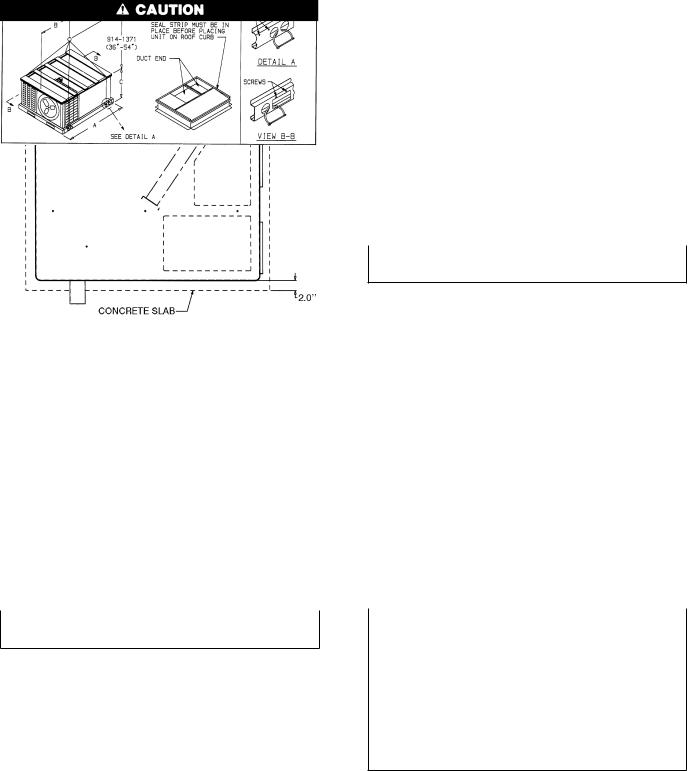
Fig. 11 Ð Slab Mounting Details
NOTICE TO RIGGERS
Hook rigging shackles through holes in lifting brackets, as shown in Detail ``A.'' Lifting brackets to be centered around the unit center of gravity. Use wooden top skid when rigging, to prevent rigging straps from damaging unit.
All panels must be in place when rigging.
UNIT |
MAX |
A |
|
|
B |
C |
|
|||
48SS |
WEIGHT |
|
|
|
||||||
|
|
|
|
|
|
|
|
|||
Size |
lb |
kg |
in. |
|
mm |
in. |
|
mm |
in. |
mm |
018 |
332 |
150 |
|
|
|
24.3 |
|
618 |
24.85 |
631 |
024 |
375 |
170 |
|
|
|
22.4 |
|
570 |
24.85 |
631 |
030 |
384 |
174 |
|
|
|
22.3 |
|
565 |
24.85 |
631 |
036 |
408 |
185 |
49.4 |
|
1255 |
22.0 |
|
559 |
24.85 |
631 |
042 |
447 |
203 |
|
|
|
22.5 |
|
571 |
28.85 |
733 |
048 |
486 |
220 |
|
|
|
21.0 |
|
533 |
34.85 |
885 |
060 |
525 |
238 |
|
|
|
21.5 |
|
545 |
34.85 |
885 |
UNIT |
|
|
|
|
|
|
|
|
|
|
48SX |
|
|
|
|
|
|
|
|
|
|
024 |
405 |
184 |
|
|
|
22.8 |
|
579 |
28.9 |
733 |
030 |
408 |
185 |
|
|
|
22.4 |
|
569 |
28.9 |
733 |
036 |
438 |
199 |
49.4 |
|
1255 |
22.4 |
|
569 |
28.9 |
733 |
042 |
463 |
210 |
|
22.8 |
|
579 |
34.9 |
885 |
||
|
|
|
|
|||||||
048 |
494 |
224 |
|
|
|
21.1 |
|
536 |
34.9 |
885 |
060 |
525 |
238 |
|
|
|
21.5 |
|
545 |
34.9 |
885 |
Fig. 12 Ð Suggested Rigging for Units Without Base Rail
NOTICE TO RIGGERS
Hook rigging shackles through holes in lifting brackets, as shown in Detail ``A.'' Lifting brackets to be centered around the unit center of gravity. Use wood top skid when rigging, to prevent rigging straps from damaging unit. Remove 4 screws to slide wood support through rectangular hole in rail.
All panels must be in place when rigging.
UNIT |
MAX |
A |
|
|
B |
|
C |
||||
48SS |
WEIGHT |
|
|
|
|||||||
|
|
|
|
|
|
|
|
|
|||
Size |
lb |
kg |
in. |
|
mm |
in. |
|
mm |
in. |
|
mm |
018 |
320 |
145 |
|
|
|
24.4 |
|
619 |
28.2 |
|
715 |
024 |
363 |
165 |
|
|
|
22.6 |
|
574 |
28.2 |
|
715 |
030 |
380 |
172 |
|
|
|
22.5 |
|
571 |
28.2 |
|
715 |
036 |
396 |
180 |
49.4 |
|
1255 |
22.2 |
|
563 |
28.2 |
|
715 |
042 |
435 |
197 |
|
|
|
22.6 |
|
574 |
32.2 |
|
816 |
048 |
474 |
215 |
|
|
|
21.2 |
|
538 |
38.2 |
|
969 |
060 |
513 |
233 |
|
|
|
21.6 |
|
549 |
38.2 |
|
969 |
UNIT |
|
|
|
|
|
|
|
|
|
|
|
48SX |
|
|
|
|
|
|
|
|
|
|
|
024 |
393 |
178 |
|
|
|
22.9 |
|
582 |
32.2 |
|
816 |
030 |
396 |
180 |
|
|
|
22.6 |
|
574 |
32.2 |
|
816 |
036 |
426 |
193 |
49.4 |
|
1255 |
22.5 |
|
571 |
32.2 |
|
816 |
042 |
451 |
205 |
|
22.9 |
|
582 |
38.2 |
|
969 |
||
|
|
|
|
|
|||||||
048 |
482 |
219 |
|
|
|
21.3 |
|
540 |
38.2 |
|
969 |
060 |
513 |
233 |
|
|
|
21.6 |
|
549 |
38.2 |
|
969 |
Fig. 13 Ð Suggested Rigging for Units With Optional Base Rail
UNITS WITHOUT BASE RAIL Ð If accessory rigging brackets are to be used for rigging, install them as follows:
Secure screws and paint protectors solidly against unit basepan to hold lifting brackets in position.
Never use lifting brackets when the temperature is below −10 F.
Never exceed 200 lbs per bracket of lifting force.
Never use lifting brackets for lifting other models of airconditioning units.
Lifting point should be directly over the unit center of gravity.
1.Position brackets as close to the corners of unit as possible. Be sure brackets are well outside of center of gravity. (See Fig. 2, 4, 6, 8, and 12.).
2.Position paint protectors and foam strips between screws and painted surface of unit. Tighten screws until they make contact with the paint protectors.
3.Secure device or hook of sufficient strength to hole in bracket as shown in detail ``A'' of Fig. 12.
4.If wood top is available, use it for a spreader bar to prevent straps from damaging unit. If wood top is not available, use spreader bars of sufficient length.
12

UNITS WITH OPTIONAL BASE RAIL Ð Lifting holes are provided in optional base rail as shown in Fig. 13. Operating weights are shown in Tables 1 and 2. Refer to rigging instructions on unit.
Protective wood support must be removed from unit before unit is mounted to curb. Remove 4 screws that secure support above rigging holes in rails. Slide support out through rectangular hole in rail. See Fig. 13.
Step 6 Ð Connect Condensate Drain
NOTE: When installing condensate drain connection be sure to comply with local codes and restrictions.
Model 48SS,SX disposes of condensate water through a 3¤4 in. NPT ®tting which exits through the compressor access panel. See Fig. 2-9 for location.
Condensate water can be drained directly onto the roof in rooftop installations (where permitted) or onto a gravel apron in ground-level installations. Install a ®eld-supplied condensate trap at end of condensate connection to ensure proper drainage. Make sure that the outlet of the trap is at least 1 in. lower than the drain-pan condensate connection to prevent the pan from over¯owing. See Fig. 14. Prime the trap with water. When using a gravel apron, make sure it slopes away from the unit.
If the installation requires draining the condensate water away from the unit, install a 2-in. trap at the condensate connection to ensure proper drainage. See Fig. 14. Make sure that the outlet of the trap is at least 1 in. lower than the drainpan condensate connection to prevent the pan from over- ¯owing. Prime the trap with water. Connect a drain tube using a minimum of 3¤4-in. PVC or 3¤4-in. copper pipe (all ®eldsupplied) at the outlet end of the 2-in. trap. Do not undersize the tube. Pitch the drain tube downward at a slope of at least one in. for every 10 ft of horizontal run. Be sure to check the drain tube for leaks.
Fig. 14 Ð Condensate Trap
Step 7 Ð Install Flue Hood Ð The ¯ue hood assembly is shipped screwed to the control box in the burner compartment. Remove the burner access panel to locate the assembly.
For units being installed in California Air Quality Management Districts which require NOx emissions of 40 nanograms/joule or less, kit CRLOWNOX001A00 must be installed.
The venting system is designed to ensure proper venting. The ¯ue hood assembly must be installed as indicated in this section of the unit installation instructions.
Install the ¯ue hood as follows:
1.This installation must conform with local building codes and with the National Fuel Gas Code (NFGC), ANSI Z223.1 (in Canada, CAN/CGA B149.1, and B149.2) or NFPA (National Fire Protection Association) latest revision. Refer
to Provincial and local plumbing or wastewater codes and other applicable local codes.
2.Remove from shipping location. Place vent cap assembly over ¯ue panel. Orient screw holes in vent cap with holes in the ¯ue panel.
3.Secure ¯ue hood to ¯ue panel by inserting a single screw on the right side, the left side, and the top of the hood.
Step 8 Ð Install Gas Piping Ð The gas supply pipe enters the unit through the access hole provided. The gas connection to the unit is made to the 1¤2-in. FPT gas inlet on the manual shutoff or gas valve.
Install a gas supply line that runs to the heating section. Refer to Table 3 and the NFGC for gas pipe sizing. Do not use cast-iron pipe. It is recommended that a black iron pipe is used. Check the local utility for recommendations concerning existing lines. Size gas supply piping for 0.5 in. wg maximum pressure drop. Never use pipe smaller than the 1¤2-in. FPT gas inlet on the unit gas valve.
For natural gas applications, the gas pressure at unit gas connection must not be less than 4.0 in. wg or greater than 13 in. wg while the unit is operating. For propane applications, the gas pressure must not be less than 4.0 in. wg or greater than 13 in. wg at the unit connection.
An 1¤8-in. NPT plugged tapping accessible for test gage connection must be installed immediately upstream of the gas supply connection to the furnace.
When installing the gas supply line, observe local codes pertaining to gas pipe installations. Refer to the NFGC ANSI Z223.1-1988 NFPA latest edition (in Canada, CAN/CGA B149.1, (2)-M86). In the absence of local building codes, adhere to the following pertinent recommendations:
1.Avoid low spots in long runs of pipe. Grade all pipe 1¤4 inch in every 15 ft to prevent traps. Grade all horizontal runs downward to risers. Use risers to connect to heating section and to meter.
2.Protect all segments of piping system against physical and thermal damage. Support all piping with appropriate straps, hangers, etc. Use a minimum of one hanger every 6 ft. For pipe sizes larger than 1¤2 in., follow recommendations of national codes.
3.Apply joint compound (pipe dope) sparingly and only to male threads of joint when making pipe connections. Use only pipe dope that is resistant to action of lique®ed petroleum gases as speci®ed by local and/or national codes.
Never use Te¯on tape.
4.Install sediment trap in riser leading to heating section per Fig. 15. This drip leg functions as a trap for dirt and condensate.
5.Install an accessible, external, manual main shutoff valve in gas supply pipe within 6 ft of heating section.
6.Install ground-joint union close to heating section between unit manual shutoff and external manual main shutoff valve.
7.Pressure-test all gas piping in accordance with local and national plumbing and gas codes before connecting piping to unit.
NOTE: Pressure test the gas supply system after the gas supply piping is connected to the gas valve. The supply piping must be disconnected from the gas valve during the testing of the piping systems when test pressure is in excess of 0.5 psig. Pressure test the gas supply piping system at pressures equal to or less than 0.5 psig. The unit heating section must be isolated from the gas piping system by closing the external main manual shutoff valve and slightly opening the ground-joint union.
13
Table 1 Ð Physical Data Ð Unit 48SS
UNIT SIZE 48SS |
|
018040 |
024040 |
024060 |
030040 |
030060 |
030080 |
036060 |
036080 |
036100 |
036120 |
||||||||||
NOMINAL CAPACITY (ton) |
11¤2 |
|
2 |
|
2 |
21¤2 |
21¤2 |
21¤2 |
|
3 |
|
3 |
|
3 |
|
3 |
|||||
OPERATING WEIGHT (lb) |
|
|
|
|
|
|
|
|
|
|
|
|
|
|
|
|
|
|
|
|
|
Without Base Rail |
|
272 |
303 |
315 |
320 |
332 |
332 |
336 |
336 |
348 |
348 |
||||||||||
With Optional Base Rail |
296 |
327 |
339 |
344 |
356 |
356 |
360 |
360 |
372 |
372 |
|||||||||||
COMPRESSORS |
|
Rotary |
|
|
|
|
|
|
|
|
Reciprocating |
|
|
|
|
|
|
|
|||
Quantity |
|
|
1 |
|
|
|
|
|
|
|
|
|
1 |
|
|
|
|
|
|
|
|
REFRIGERANT (R-22) |
|
|
|
|
|
|
|
|
|
|
|
|
|
|
|
|
|
|
|
|
|
Charge (lb) |
|
2.60 |
2.75 |
2.75 |
3.40 |
3.40 |
3.40 |
4.30 |
4.30 |
4.30 |
4.30 |
||||||||||
REFRIGERANT METERING DEVICE |
|
|
|
|
|
|
|
|
|
Acutrol™ Device |
|
|
|
|
|
|
|
|
|||
Ori®ce ID (in.) |
|
.030 |
.030 |
.030 |
.030 |
.030 |
.030 |
.032 |
.032 |
.032 |
.032 |
||||||||||
CONDENSER COIL |
|
|
|
|
|
|
|
|
|
|
|
|
|
|
|
|
|
|
|
|
|
Rows...Fins/in. |
|
1... |
17 |
1... |
17 |
1... |
17 |
2... |
17 |
2... |
17 |
2... |
17 |
2... |
17 |
2... |
17 |
2... |
17 |
2... |
17 |
Face Area (sq ft) |
|
5.95 |
5.95 |
5.95 |
5.95 |
5.95 |
5.95 |
5.95 |
5.95 |
5.95 |
5.95 |
||||||||||
CONDENSER FAN |
|
|
|
|
|
|
|
|
|
|
|
|
|
|
|
|
|
|
|
|
|
Nominal Cfm |
|
1700 |
1700 |
1700 |
1900 |
1900 |
1900 |
1900 |
1900 |
1900 |
1900 |
||||||||||
Diameter (in.) |
|
|
18 |
|
18 |
|
18 |
|
18 |
|
18 |
|
18 |
|
18 |
|
18 |
|
18 |
|
18 |
Motor Hp (Rpm) |
|
1¤8 (850) |
1¤8 (850) |
1¤8 (850) |
1¤8 (850) |
1¤8 (850) |
1¤8 (850) |
1¤4 (1050) |
1¤4 (1050) |
1¤4 (1050) |
1¤4 (1050) |
||||||||||
EVAPORATOR COIL |
|
3 |
15 |
3 |
15 |
3 |
15 |
3 |
15 |
3 |
15 |
3 |
15 |
3 |
15 |
3 |
15 |
3 |
15 |
3 |
15 |
Rows Fins/in. |
|
||||||||||||||||||||
Face Area (sq ft) |
|
1.83 |
2.29 |
2.29 |
2.29 |
2.29 |
2.29 |
3.06 |
3.06 |
3.06 |
3.06 |
||||||||||
EVAPORATOR FAN |
|
|
|
|
|
|
|
|
|
|
Direct Drive |
|
|
|
|
|
|
|
|
||
Nominal Air¯ow (Cfm) |
600 |
800 |
800 |
1000 |
1000 |
1000 |
1200 |
1200 |
1200 |
1200 |
|||||||||||
Size (in.) |
|
10 x 10 |
10 x 10 |
10 x 10 |
10 x 10 |
10 x 10 |
10 x 10 |
10 x 10 |
10 x 10 |
10 x 10 |
10 x 10 |
||||||||||
Motor Hp |
|
|
1¤4 |
|
1¤4 |
|
1¤4 |
|
1¤4 |
|
1¤4 |
|
1¤4 |
|
1¤2 |
|
1¤2 |
|
1¤2 |
|
1¤2 |
FURNACE SECTION* |
|
|
|
|
|
|
|
|
|
|
|
|
|
|
|
|
|
|
|
|
|
Burner Ori®ce (Qty... |
drill size) |
1 |
32 |
1 |
32 |
2 |
40 |
1 |
32 |
2 |
40 |
2 |
32 |
2 |
40 |
2 |
32 |
2 |
30 |
3 |
32 |
Natural Gas |
|
||||||||||||||||||||
|
|
|
|
|
|
|
|
|
|
|
|
|
|
|
|
|
|
|
|
|
|
Burner Ori®ce (Qty... |
drill size) |
1 |
41 |
1 |
41 |
2 |
47 |
1 |
41 |
2 |
47 |
2 |
42 |
2 |
47 |
2 |
42 |
2 |
40 |
3 |
42 |
Propane Gas |
|
||||||||||||||||||||
|
|
|
|
|
|
|
|
|
|
|
|
|
|
|
|
|
|
|
|
|
|
RETURN-AIR FILTERS (in.)² |
|
|
|
|
|
|
|
|
|
|
|
|
|
|
|
|
|
|
|
|
|
Throwaway |
|
20 x 20 |
20 x 20 |
20 x 20 |
20 x 24 |
20 x 24 |
20 x 24 |
20 x 24 |
20 x 24 |
20 x 24 |
20 x 24 |
||||||||||
UNIT SIZE 48SS |
|
042060 |
042080 |
|
042100 |
042120 |
048080 |
048100 |
048120 |
048140 |
|
060080 |
060100 |
060120 |
060140 |
||||||||||||
NOMINAL CAPACITY (ton) |
31¤2 |
31¤2 |
|
31¤2 |
31¤2 |
|
4 |
|
4 |
|
4 |
|
4 |
|
|
5 |
|
5 |
|
5 |
|
5 |
|||||
OPERATING WEIGHT (lb) |
|
|
|
|
|
|
|
|
|
|
|
|
|
|
|
|
|
|
|
|
|
|
|
|
|
|
|
Without Base Rail |
|
375 |
375 |
|
387 |
387 |
414 |
426 |
426 |
426 |
|
453 |
465 |
465 |
465 |
||||||||||||
With Optional Base Rail |
399 |
399 |
|
411 |
411 |
438 |
450 |
450 |
450 |
|
477 |
489 |
489 |
489 |
|||||||||||||
COMPRESSORS |
|
|
|
|
Reciprocating |
|
|
|
|
|
|
|
|
Hermetic Scroll |
|
|
|
|
|
|
|||||||
Quantity |
|
|
|
|
|
1 |
|
|
|
|
|
|
|
|
|
|
|
1 |
|
|
|
|
|
|
|
||
REFRIGERANT (R-22) |
|
|
|
|
|
|
|
|
|
|
|
|
|
|
|
|
|
|
|
|
|
|
|
|
|
|
|
Charge (lb) |
|
5.20 |
5.20 |
|
5.20 |
5.20 |
6.50 |
6.50 |
6.50 |
6.50 |
|
7.00 |
7.00 |
7.00 |
7.00 |
||||||||||||
REFRIGERANT METERING |
|
|
|
|
|
|
|
|
|
|
|
Acutrol Device |
|
|
|
|
|
|
|
|
|
|
|
||||
DEVICE |
|
|
|
|
|
|
|
|
|
|
|
|
|
|
|
|
|
|
|
|
|
|
|
|
|
|
|
Ori®ce ID (in.) |
|
.034 |
.034 |
|
.034 |
.034 |
.030 |
.030 |
.030 |
.030 |
|
.030 |
.030 |
.030 |
.030 |
||||||||||||
CONDENSER COIL |
|
|
|
|
|
|
|
|
|
|
|
|
|
|
|
|
|
|
|
|
|
|
|
|
|
|
|
Rows...Fins/in. |
|
2 |
...17 |
2 |
...17 |
|
2 |
...17 |
2 |
...17 |
2 |
...17 |
2 |
...17 |
2 |
...17 |
2 |
...17 |
|
2 |
...17 |
2 |
...17 |
2 |
...17 |
2 |
...17 |
Face Area (sq ft) |
|
7.04 |
7.04 |
|
7.04 |
7.04 |
8.67 |
8.67 |
8.67 |
8.67 |
|
8.67 |
8.67 |
8.67 |
8.67 |
||||||||||||
CONDENSER FAN |
|
|
|
|
|
|
|
|
|
|
|
|
|
|
|
|
|
|
|
|
|
|
|
|
|
|
|
Nominal Cfm |
|
1900 |
1900 |
|
1900 |
1900 |
2400 |
2400 |
2400 |
2400 |
|
2400 |
2400 |
2400 |
2400 |
||||||||||||
Diameter (in.) |
|
|
18 |
|
18 |
|
|
18 |
|
18 |
|
20 |
|
20 |
|
20 |
|
20 |
|
|
20 |
|
20 |
|
20 |
|
20 |
Motor Hp (Rpm) |
|
1¤4 (1050) |
1¤4 (1050) |
|
1¤4 (1050) |
1¤4 (1050) |
1¤3 (1050) |
1¤3 (1050) |
1¤3 (1050) |
1¤3 (1050) |
|
1¤3 (1050) |
1¤3 (1050) |
1¤3 (1050) |
1¤3 (1050) |
||||||||||||
EVAPORATOR COIL |
|
|
|
|
|
|
|
|
|
|
|
|
|
|
|
|
|
|
|
|
|
|
|
|
|
|
|
Rows Fins/in. |
|
3... |
15 |
3... |
15 |
|
3... |
15 |
3... |
15 |
3... |
15 |
3... |
15 |
3... |
15 |
3... |
15 |
|
4... |
15 |
4... |
15 |
4... |
15 |
4... |
15 |
Face Area (sq ft) |
|
3.33 |
3.33 |
|
3.33 |
3.33 |
4.44 |
4.44 |
4.44 |
4.44 |
|
4.44 |
4.44 |
4.44 |
4.44 |
||||||||||||
EVAPORATOR FAN |
|
|
|
|
|
|
|
|
|
|
|
|
|
Direct Drive |
|
|
|
|
|
|
|
|
|
|
|
||
Nominal Air¯ow (Cfm) |
1400 |
1400 |
|
1400 |
1400 |
1600 |
1600 |
1600 |
1600 |
|
1995 |
1995 |
1995 |
1995 |
|||||||||||||
Size (in.) |
|
10 x 10 |
10 x 10 |
|
10 x 10 |
10 x 10 |
10 x 10 |
10 x 10 |
10 x 10 |
10 x 10 |
|
10 x 11 |
10 x 11 |
10 x 11 |
10 x 11 |
||||||||||||
Motor Hp |
|
|
3 ¤4 |
|
3 ¤4 |
|
|
3 ¤4 |
|
3 ¤4 |
|
3 ¤4 |
|
3 ¤4 |
|
3 ¤4 |
|
3 ¤4 |
|
|
1 |
|
1 |
|
1 |
|
1 |
FURNACE SECTION* |
|
|
|
|
|
|
|
|
|
|
|
|
|
|
|
|
|
|
|
|
|
|
|
|
|
|
|
Burner Ori®ce (Qty... |
drill size) |
2 |
40 |
2 |
32 |
|
2 |
30 |
3 |
32 |
2 |
32 |
2 |
30 |
3 |
32 |
3 |
31 |
|
2 |
32 |
2 |
30 |
3 |
32 |
3 |
31 |
Natural Gas |
|
|
|
||||||||||||||||||||||||
|
|
|
|
|
|
|
|
|
|
|
|
|
|
|
|
|
|
|
|
|
|
|
|
|
|
|
|
Burner Ori®ce (Qty... |
drill size) |
2 |
47 |
2 |
42 |
|
2 |
40 |
3 |
42 |
2 |
42 |
2 |
40 |
3 |
42 |
3 |
40 |
|
3 |
42 |
2 |
40 |
3 |
42 |
3 |
40 |
Propane Gas |
|
|
|
||||||||||||||||||||||||
|
|
|
|
|
|
|
|
|
|
|
|
|
|
|
|
|
|
|
|
|
|
|
|
|
|
|
|
RETURN-AIR FILTERS (in.)² |
|
|
|
|
|
|
|
|
|
|
|
|
|
|
|
|
|
|
|
|
|
|
|
|
|
|
|
Throwaway |
|
24 x 24 |
24 x 24 |
|
24 x 24 |
24 x 24 |
24 x 30 |
24 x 30 |
24 x 30 |
24 x 30 |
|
24 x 30 |
24 x 30 |
24 x 30 |
24 x 30 |
||||||||||||
*Based on altitude of 0-2000 feet.
²Required ®lter sizes shown are based on the larger of the ARI (Air Conditioning & Refrigeration Institute) rated cooling air¯ow or the heating air¯ow at a velocity of 300 ft/min for throwaway type or 450 ft/min for high-capacity type. For non-standard air ®lters, air ®lter pressure drop must not exceed 0.08 in. wg.
14
Table 2 Ð Physical Data Ð Unit 48SX
UNIT SIZE 48SX |
|
024040 |
024060 |
030040 |
030060 |
|
030080 |
|
036060 |
036080 |
036100 |
036120 |
|||||||||
NOMINAL CAPACITY (ton) |
|
2 |
|
2 |
21¤2 |
21¤2 |
|
21¤2 |
|
|
3 |
|
3 |
|
3 |
|
3 |
||||
OPERATING WEIGHT (lb) |
|
|
|
|
|
|
|
|
|
|
|
|
|
|
|
|
|
|
|
|
|
Without Base Rail |
|
333 |
345 |
336 |
348 |
|
348 |
|
366 |
366 |
378 |
378 |
|||||||||
With Optional Base Rail |
357 |
369 |
360 |
372 |
|
372 |
|
390 |
390 |
402 |
402 |
||||||||||
COMPRESSORS |
|
|
|
|
|
|
|
|
|
|
Scroll |
|
|
|
|
|
|
|
|
||
Quantity |
|
|
|
|
|
|
|
|
|
|
|
1 |
|
|
|
|
|
|
|
|
|
REFRIGERANT (R-22) |
|
|
|
|
|
|
|
|
|
|
|
|
|
|
|
|
|
|
|
|
|
Charge (lb) |
|
|
3.9 |
|
3.9 |
|
4.5 |
|
4.5 |
|
|
4.5 |
|
|
5.4 |
|
5.4 |
|
5.4 |
|
5.4 |
REFRIGERANT METERING DEVICE |
|
|
|
|
|
|
|
|
Acutrol™ Device |
|
|
|
|
|
|
|
|
||||
Ori®ce ID (in.) |
|
.034 |
.034 |
.030 |
.030 |
|
.030 |
|
.032 |
.032 |
.032 |
.032 |
|||||||||
CONDENSER COIL |
|
|
|
|
|
|
|
|
|
|
|
|
|
|
|
|
|
|
|
|
|
Rows...Fins/in. |
|
2 |
...17 |
2 |
...17 |
2 |
...17 |
2... |
17 |
|
2... |
17 |
|
2... |
17 |
2... |
17 |
2... |
17 |
2... |
17 |
Face Area (sq ft) |
|
|
7.0 |
|
7.0 |
|
7.0 |
|
7.0 |
|
|
7.0 |
|
|
7.0 |
|
7.0 |
|
7.0 |
|
7.0 |
CONDENSER FAN |
|
|
|
|
|
|
|
|
|
|
|
|
|
|
|
|
|
|
|
|
|
Nominal Cfm |
|
2200 |
2200 |
2200 |
2200 |
|
2200 |
|
2200 |
2200 |
2200 |
2200 |
|||||||||
Diameter (in.) |
|
|
20 |
|
20 |
|
20 |
|
20 |
|
|
20 |
|
|
20 |
|
20 |
|
20 |
|
20 |
Motor Hp (Rpm) |
|
1¤4 (1100) |
1¤4 (1100) |
1¤4 (1100) |
1¤4 (1100) |
|
1¤4 (1100) |
|
1¤4 (1100) |
1¤4 (1100) |
1¤4 (1100) |
1¤4 (1100) |
|||||||||
EVAPORATOR COIL |
|
2 |
15 |
2 |
15 |
3 |
15 |
3 |
15 |
|
3 |
15 |
|
4 |
15 |
4 |
15 |
4 |
15 |
4 |
15 |
Rows Fins/in. |
|
|
|
||||||||||||||||||
Face Area (sq ft) |
|
|
3.6 |
|
3.6 |
|
2.7 |
|
2.7 |
|
|
2.7 |
|
|
3.6 |
|
3.6 |
|
3.6 |
|
3.6 |
EVAPORATOR FAN* |
|
|
|
|
|
|
|
|
|
|
Direct Drive |
|
|
|
|
|
|
|
|
||
Nominal Air¯ow (Cfm) |
800 |
800 |
1000 |
1000 |
|
1000 |
|
1200 |
1200 |
1200 |
1200 |
||||||||||
Size (in.) |
|
10 x 10 |
10 x 10 |
10 x 10 |
10 x 10 |
|
10 x 10 |
|
10 x 10 |
10 x 10 |
10 x 10 |
10 x 10 |
|||||||||
Motor Hp |
|
|
1¤4 |
|
1¤4 |
|
1¤4 |
|
1¤4 |
|
|
1¤4 |
|
|
1¤2 |
|
1¤2 |
|
1¤2 |
|
1¤2 |
FURNACE SECTION² |
|
|
|
|
|
|
|
|
|
|
|
|
|
|
|
|
|
|
|
|
|
Burner Ori®ce (Qty... |
drill size) |
1 |
32 |
2 |
40 |
1 |
32 |
2 |
40 |
|
2 |
32 |
|
2 |
40 |
2 |
32 |
2 |
30 |
3 |
32 |
Natural Gas |
|
|
|
||||||||||||||||||
|
|
|
|
|
|
|
|
|
|
|
|
|
|
|
|
|
|
|
|
|
|
Burner Ori®ce (Qty... |
drill size) |
1 |
41 |
2 |
47 |
1 |
41 |
2 |
47 |
|
2 |
42 |
|
2 |
47 |
2 |
42 |
2 |
40 |
3 |
42 |
Propane Gas |
|
|
|
||||||||||||||||||
|
|
|
|
|
|
|
|
|
|
|
|
|
|
|
|
|
|
|
|
|
|
RETURN-AIR FILTERS (in.)** |
|
|
|
|
|
|
|
|
|
|
|
|
|
|
|
|
|
|
|
|
|
Disposable |
|
24 x 24 |
24 x 24 |
24 x 24 |
24 x 24 |
|
24 x 24 |
|
24 x 24 |
24 x 24 |
24 x 24 |
24 x 24 |
|||||||||
UNIT SIZE 48SX |
|
042060 |
042080 |
042100 |
042120 |
048080 |
048100 |
048120 |
048140 |
060080 |
060100 |
060120 |
060140 |
||||||||||||
NOMINAL CAPACITY (ton) |
31¤2 |
31¤2 |
31¤2 |
31¤2 |
|
4 |
|
4 |
|
4 |
|
4 |
|
5 |
|
5 |
|
5 |
|
5 |
|||||
OPERATING WEIGHT (lb) |
|
|
|
|
|
|
|
|
|
|
|
|
|
|
|
|
|
|
|
|
|
|
|
|
|
Without Base Rail |
|
391 |
391 |
403 |
403 |
422 |
434 |
434 |
434 |
453 |
465 |
465 |
465 |
||||||||||||
With Optional Base Rail |
415 |
415 |
427 |
427 |
446 |
458 |
458 |
458 |
477 |
489 |
489 |
489 |
|||||||||||||
COMPRESSORS |
|
|
|
|
|
|
|
|
|
|
|
|
Scroll |
|
|
|
|
|
|
|
|
|
|
|
|
Quantity |
|
|
|
|
|
|
|
|
|
|
|
|
1 |
|
|
|
|
|
|
|
|
|
|
|
|
REFRIGERANT (R-22) |
|
|
|
|
|
|
|
|
|
|
|
|
|
|
|
|
|
|
|
|
|
|
|
|
|
Charge (lb) |
|
|
5.7 |
|
5.7 |
|
5.7 |
|
5.7 |
|
5.8 |
|
5.8 |
|
5.8 |
|
5.8 |
7.00 |
7.00 |
7.00 |
7.00 |
||||
REFRIGERANT METERING |
|
|
|
|
|
|
|
|
|
|
Acutrol Device |
|
|
|
|
|
|
|
|
|
|
||||
DEVICE |
|
|
|
|
|
|
|
|
|
|
|
|
|
|
|
|
|
|
|
|
|
|
|
|
|
Ori®ce ID (in.) |
|
.034 |
.034 |
.034 |
.034 |
.034 |
.034 |
.034 |
.034 |
.030 |
.030 |
.030 |
.030 |
||||||||||||
CONDENSER COIL |
|
|
|
|
|
|
|
|
|
|
|
|
|
|
|
|
|
|
|
|
|
|
|
|
|
Rows...Fins/in. |
|
2 |
...17 |
2 |
...17 |
2 |
...17 |
2 |
...17 |
2 |
...17 |
2 |
...17 |
2 |
...17 |
2 |
...17 |
2 |
...17 |
2 |
...17 |
2 |
...17 |
2 |
...17 |
Face Area (sq ft) |
|
|
8.7 |
|
8.7 |
|
8.7 |
|
8.7 |
|
8.7 |
|
8.7 |
|
8.7 |
|
8.7 |
8.67 |
8.67 |
8.67 |
8.67 |
||||
CONDENSER FAN |
|
|
|
|
|
|
|
|
|
|
|
|
|
|
|
|
|
|
|
|
|
|
|
|
|
Nominal Cfm |
|
2400 |
2400 |
2400 |
2400 |
2400 |
2400 |
2400 |
2400 |
2400 |
2400 |
2400 |
2400 |
||||||||||||
Diameter (in.) |
|
|
20 |
|
20 |
|
20 |
|
20 |
|
20 |
|
20 |
|
20 |
|
20 |
|
20 |
|
20 |
|
20 |
|
20 |
Motor Hp (Rpm) |
|
1¤4 (1100) |
1¤4 (1100) |
1¤4 (1100) |
1¤4 (1100) |
1¤4 (1100) |
1¤4 (1100) |
1¤4 (1100) |
1¤4 (1100) |
1¤3 (1050) |
1¤3 (1050) |
1¤3 (1050) |
1¤3 (1050) |
||||||||||||
EVAPORATOR COIL |
|
|
|
|
|
|
|
|
|
|
|
|
|
|
|
|
|
|
|
|
|
|
|
|
|
Rows Fins/in. |
|
3 |
...15 |
3 |
...15 |
3 |
...15 |
3 |
...15 |
4 |
...15 |
4 |
...15 |
4 |
...15 |
4 |
...15 |
4... |
15 |
4... |
15 |
4... |
15 |
4... |
15 |
Face Area (sq ft) |
|
|
4.4 |
|
4.4 |
|
4.4 |
|
4.4 |
|
4.4 |
|
4.4 |
|
4.4 |
|
4.4 |
4.44 |
4.44 |
4.44 |
4.44 |
||||
EVAPORATOR FAN* |
|
|
|
|
|
|
|
|
|
|
|
Direct Drive |
|
|
|
|
|
|
|
|
|
|
|||
Nominal Air¯ow (Cfm) |
1400 |
1400 |
1400 |
1400 |
1600 |
1600 |
1600 |
1600 |
1995 |
1995 |
1995 |
1995 |
|||||||||||||
Size (in.) |
|
10 x 10 |
10 x 10 |
10 x 10 |
10 x 10 |
10 x 10 |
10 x 10 |
10 x 10 |
10 x 10 |
10 x 11 |
10 x 11 |
10 x 11 |
10 x 11 |
||||||||||||
Motor Hp |
|
|
3¤4 |
|
3¤4 |
|
3¤4 |
|
3¤4 |
|
3¤4 |
|
3¤4 |
|
3¤4 |
|
3¤4 |
|
1 |
|
1 |
|
1 |
|
1 |
FURNACE SECTION² |
|
|
|
|
|
|
|
|
|
|
|
|
|
|
|
|
|
|
|
|
|
|
|
|
|
Burner Ori®ce (Qty... |
drill size) |
2 |
40 |
2 |
32 |
2 |
30 |
3 |
32 |
2 |
32 |
2 |
30 |
3 |
32 |
3 |
31 |
2 |
32 |
2 |
30 |
3 |
32 |
3 |
31 |
Natural Gas |
|
||||||||||||||||||||||||
|
|
|
|
|
|
|
|
|
|
|
|
|
|
|
|
|
|
|
|
|
|
|
|
|
|
Burner Ori®ce (Qty... |
drill size) |
2 |
47 |
2 |
42 |
2 |
40 |
3 |
42 |
2 |
42 |
2 |
40 |
3 |
42 |
3 |
40 |
3 |
42 |
2 |
40 |
3 |
42 |
3 |
40 |
Propane Gas |
|
||||||||||||||||||||||||
|
|
|
|
|
|
|
|
|
|
|
|
|
|
|
|
|
|
|
|
|
|
|
|
|
|
RETURN-AIR FILTERS (in.)** |
|
|
|
|
|
|
|
|
|
|
|
|
|
|
|
|
|
|
|
|
|
|
|
|
|
Disposable |
|
24 x 30 |
24 x 30 |
24 x 30 |
24 x 30 |
24 x 30 |
24 x 30 |
24 x 30 |
24 x 30 |
24 x 30 |
24 x 30 |
24 x 30 |
24 x 30 |
||||||||||||
*Size 048 evaporator fan is equipped with a 460-v or integrated control motor (ICM). Size 060 evaporator fan is equipped with an ICM only. The ICM provides variable speed.
²Based on an altitude of 0-2000 feet.
**Required ®lter sizes shown are based on the ARI (Air Conditioning & Refrigeration Institute) rated heating air¯ow at a velocity of 300 ft/min for throwaway type or 450 ft/min for high-capacity type. For non-standard air ®lters, air ®lter pressure drop must not exceed 0.08 in. wg.
15
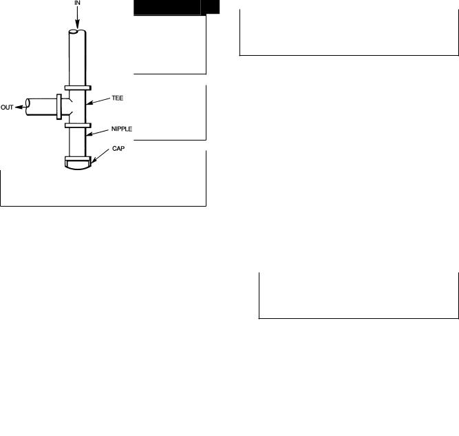
(Text continued from page 13)
Unstable operation may occur when the gas valve and manifold assembly are forced out of position while connecting improperly-routed rigid gas piping to the gas valve. Use a backup wrench when making connection to avoid strain on, or distortion of, the gas control piping.
If a ¯exible conductor is required or allowed by the authority having jurisdiction, black iron pipe shall be installed at the gas valve and shall extend a minimum of 2 in. outside the unit casing.
Never use a match or other open ¯ame when checking for gas leaks. Never purge gas line into combustion chamber. Failure to follow this warning could result in an explosion causing personal injury or death.
8.Check for gas leaks at the ®eld-installed and factoryinstalled gas lines after all piping connections have been completed. Use soap-and-water solution (or method speci- ®ed by local codes and/or regulations).
Fig. 15 Ð Sediment Trap
Step 9 Ð Install Duct Connections Ð The unit has duct ¯anges on the supplyand return-air openings on the side and bottom of the unit. See Fig. 2-9 for connection sizes and locations.
CONFIGURING UNITS FOR DOWNFLOW (VERTICAL) DISCHARGE
Before performing service or maintenance operations on the system, turn off main power to unit or electrical shock could result.
1.Open all electrical disconnects before starting any service work.
2.Remove return duct cover located on duct panel. Figure 16 shows duct cover removed. Save duct cover and screws.
3.Locate lances in basepan insulation that are placed over
the perimeter of the vertical duct opening cover (Fig. 17).
4.Using a straight edge and sharp knife, cut and remove the insulation around the perimeter of the cover. Remove and save 5 screws securing the cover to the basepan and slide out the cover. Discard the cover (Fig. 18).
5.Remove supply duct cover located on duct panel. Figure 16 shows duct cover removed. Save duct cover and screws.
6.Remove and discard 2 screws which secure vertical discharge opening cover to basepan (Fig. 19). Slide cover forward to disengage, then tilt and remove cover through vertical discharge opening in bottom of unit. Discard duct cover (Fig. 20).
Collect ALL screws that were removed. Do not leave screws on rooftop as permanent damage to the roof may occur.
7.If unit ductwork is to be attached to vertical opening ¯anges on the unit basepan (jackstand applications only), do so at this time.
8.It is recommended that the basepan insulation around the perimeter of the vertical return-air opening be secured to the basepan with aluminum tape. Applicable local codes may require aluminum tape to prevent exposed ®berglass.
9.Cover both horizontal duct openings with the duct covers from Steps 2 and 5. Make sure opening is airand watertight.
10.After completing unit conversion, perform all safety checks and power up unit.
NOTE: The design and installation of the duct system must be in accordance with the standards of the NFPA for installation of nonresidence-type air conditioning and ventilating systems, NFPA 90A or residence-type, NFPA 90B; and/or local codes and residence-type, NFPA 90B; and/or local codes and ordinances.
16
 Loading...