


Product
Data
48SS Single-Package Gas Heating/Electric Cooling Units
11¤2 to 5 Nominal Tons
Single-Package Rooftop Products with Energy-Saving Features
·direct spark ignition
·low sound levels
·81% AFUE on most units
·10 SEER
Features/Bene®ts
One-piece heating and cooling units with low installation costs, dependable performance, and easy maintenance
Easy installation
Factory-assembled package is a compact, fully self-contained, combination gas heating/electric cooling unit that is prewired, prepiped, and precharged for minimum installation expense.
These 48SS units are available in a variety of standard and optional heating/cooling size combinations with voltage options to meet residential and light commercial requirements. Units are lightweight and install easily on a rooftop or a ground-level pad.
Convertible duct con®guration
Unit is designed for easy use in either down¯ow or horizontal applications.
Ef®cient operation
High-ef®ciency design with SEERs (Seasonal Energy Ef®ciency Ratios) of 10.0 and AFUE (Annual Fuel Utilization Ef®ciency) ratings as high as 81.0%. All units have a minimum CSE (California Seasonal Ef®ciency) rating of 76.5%.
Copyright 1998 Carrier Corporation |
Form 48SS-4PD |

Energy-saving, direct-spark ignition saves gas by operating only when the room thermostat calls for heating. Standard units are furnished with natural gas controls. A lowcost, ®eld-installed kit for propane conversion is available for all units.
Monoport inshot burners produce precise air-to-gas mixture which provides for clean and ef®cient combustion. The large monoport on the inshot (or injection type) burners seldom, if ever, needs cleaning. All
gas furnace components are accessible in one compartment.
The 48SS units meet California Air Quality Management NOx requirement of 40 nanograms/ joule or less when NOx kit
no. CRLOWNOX001A00 is installed.
Durable, dependable components
Top quality, top reliability components are designed and tested for a minimum of 15 years of operation under the harshest conditions. Every 48SS unit is thoroughly run-tested
at the factory in each operating mode, and is evacuated prior to ®nal charging.
Compressors are designed for high ef®ciency. Each compressor is hermetically sealed against contamination to help promote longer life and dependable operation. Each compressor also has vibration isolation to provide quiet operation. All compressors have internal high-pressure and overcurrent protection. Rotary compressors are standard on unit
size 018. Reciprocating compressors are standard on unit sizes 024-042. Scroll compressors are standard on unit sizes 048 and 060.
Dimpled heat exchangers optimize heat transfer for improved ef®ciency. The tubular design permits hot gases to stay in close contact with the cell walls to maximize heat transfer and ef®ciency.
The induced draft combustion system eliminates the unsightly appearance of ¯ue stacks, and diminishes the effects of wind on heating operation. The induced draft also prevents contaminants from entering the supply air if a leak in the heat exchanger occurs.
Direct-drive multispeed, PSC (permanent split capacitor) blower motor is standard on all models.
Direct-drive, PSC condenser-fan motor is designed to help reduce energy consumption and provide for cooling operation down to 40 F outdoor temperature.
Refrigerant system is designed to provide dependability. Liquid refrigerant strainers are used to promote clean, unrestricted operation. Each unit leaves the factory with a full refrigerant charge. Refrigerant service connections make checking operating pressures easier.
Color-coded wires permit easy tracing and diagnostics.
Evaporator and condenser coils are computer-designed for optimum heat transfer and cooling efficiency.
Condenser coil is fabricated of copper tube and aluminum ®ns and is located inside the unit for protection against damage for long life and reliable operation. The condenser coil
is internally mounted and protected by a composite grille. Copper ®n coils are also available from the factory by special order. These coils are recommended in applications where aluminum ®ns are likely to be damaged due to corrosion and are ideal for seacoast applications.
Low sound ratings ensure a quiet indoor and outdoor environment with sound ratings as low as 7.4 bels.
Easy to service cabinets provide easy accessibility to serviceable components during maintenance and installation. Rounded corners are an important safety feature, and a high quality ®nish ensures an attractive appearance.
Optional base rails provide holes for rigging and forklifts as well as
an elevated mounting frame that provides structural support for horizontal installations. Ideal for light commercial applications.
Down¯ow option unit is converted for down¯ow at the factory to allow vertical ductwork connections. Unit is equipped with base rail.
Low and high voltage electrical entries allow low and high voltage to be brought in through either the front duct panel or rear ¯ue panel.
Integrated gas unit controller (IGC) contains all the ignition components and is easily accessible for service. The IGC provides built-in diagnostic capabilities. A light-emitting diode (LED) simpli®es troubleshooting by providing visual fault noti®- cation and system status information. The IGC board provides exclusive anti-cycle protection for gas heat operation. The IGC also contains burner control logic for dependable heating operation. The 48SS units maximize heating ef®ciency through the IGC's control of evaporator fan ON/OFF delays. The IGC helps make 48SS units reliable for years.
Weatherized cabinets are constructed of heavy-duty, phosphated, zinc-coated prepainted steel capable of withstanding 500 hours (Federal Test Method Standard No. 141, Method 6061) in salt spray. Interior surfaces of the evaporator/heat exchanger compartment are insulated with cleanable, foil-faced insulation for improved indoor-air quality. Unit conforms to American Society of Heating, Refrigeration and Air Conditioning Engineers [ASHRAE]
No. 62, with use of a sloped condensate pan. An external drain trap is required.
The standard control system is readily adaptable to all conventional and programmable thermostats. In addition, units are suitable for integration into monitor control systems if required.
Standardized components for the complete 48SS line of products are found in all safety devices, condenserfan motors, evaporator-fan motors, and control boards, while the gas sections use common inducer motors, limit switches, and rollout switches. This allows for greater inventory control, familiarity of parts, and fewer stocked parts.
2
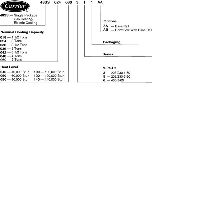
Table of contents
Page
Features/Bene®ts . . . . . . . . . . . . . . . . . . . . . . . . . . . . . . . . . . . . . . . . . . . . . . . . . . 1,2
Model Number Nomenclature . . . . . . . . . . . . . . . . . . . . . . . . . . . . . . . . . . . . . . . . 3
ARI Capacities . . . . . . . . . . . . . . . . . . . . . . . . . . . . . . . . . . . . . . . . . . . . . . . . . . . . 4,5
Physical Data . . . . . . . . . . . . . . . . . . . . . . . . . . . . . . . . . . . . . . . . . . . . . . . . . . . . . . 6
Options and Accessories . . . . . . . . . . . . . . . . . . . . . . . . . . . . . . . . . . . . . . . . . . . . . 7
Base Unit Dimensions . . . . . . . . . . . . . . . . . . . . . . . . . . . . . . . . . . . . . . . . . . . . . 8-11
Accessory Dimensions . . . . . . . . . . . . . . . . . . . . . . . . . . . . . . . . . . . . . . . . . . . 12,13
Selection Procedure . . . . . . . . . . . . . . . . . . . . . . . . . . . . . . . . . . . . . . . . . . . . . . . . 13
Performance Data . . . . . . . . . . . . . . . . . . . . . . . . . . . . . . . . . . . . . . . . . . . . . . . 14-18
Typical Installation . . . . . . . . . . . . . . . . . . . . . . . . . . . . . . . . . . . . . . . . . . . . . . . . . 19
Application Data . . . . . . . . . . . . . . . . . . . . . . . . . . . . . . . . . . . . . . . . . . . . . . . . . . 20
Typical Control Wiring Schematic . . . . . . . . . . . . . . . . . . . . . . . . . . . . . . . . . . 21-23
Electrical Data . . . . . . . . . . . . . . . . . . . . . . . . . . . . . . . . . . . . . . . . . . . . . . . . . . . . 24
Controls . . . . . . . . . . . . . . . . . . . . . . . . . . . . . . . . . . . . . . . . . . . . . . . . . . . . . . . . . . 25
Guide Speci®cations . . . . . . . . . . . . . . . . . . . . . . . . . . . . . . . . . . . . . . . . . . . . . 26,27
Model number nomenclature
3

ARI* capacities
COOLING CAPACITIES AND EFFICIENCIES
UNIT 48SS |
NOMINAL |
STANDARD |
NET COOLING² |
SEER² |
SOUND RATINGS** |
|
TONS |
CFM |
CAPACITIES |
(Bels) |
|||
|
|
|||||
018040 |
11¤2 |
600 |
17,000 |
10.0 |
7.4 |
|
024040 |
2 |
800 |
24,000 |
10.0 |
7.6 |
|
024060 |
||||||
|
|
|
|
|
||
030040 |
|
|
|
|
|
|
030060 |
21¤2 |
1000 |
29,200 |
10.0 |
8.0 |
|
030080 |
|
|
|
|
|
|
036060 |
|
|
|
|
|
|
036080 |
3 |
1200 |
36,000 |
10.0 |
8.0 |
|
036100 |
||||||
|
|
|
|
|
||
036120 |
|
|
|
|
|
|
042060 |
|
|
|
|
|
|
042080 |
31¤2 |
1400 |
42,500 |
10.0 |
8.2 |
|
042100 |
||||||
042120 |
|
|
|
|
|
|
048080 |
|
|
|
|
|
|
048100 |
4 |
1600 |
47,000 |
10.0 |
8.2 |
|
048120 |
||||||
|
|
|
|
|
||
048140 |
|
|
|
|
|
|
060080 |
|
|
|
|
|
|
060100 |
5 |
1995 |
59,500 |
10.0 |
8.2 |
|
060120 |
||||||
|
|
|
|
|
||
060140 |
|
|
|
|
|
|
|
|
|
|
|
|
|
|
LEGEND |
Bels |
Ð Sound Levels (1 bel = 10 decibels) |
|
db |
Ð Dry Bulb |
|
SEER Ð |
Seasonal Energy Efficiency Ratio |
|
wb |
Ð |
Wet Bulb |
*Air Conditioning & Refrigeration Institute.
²Rated in accordance with U.S. Government DOE (Department of Energy) test procedures and/or ARI Standard 210/240.
**Rated in accordance with ARI Standard 270.
NOTES:
1.Capacity ratings are net values, re¯ecting the effects of circulating fan heat.
Ratings are based on:
Cooling Standard: 80 F db, 67 F wb indoor entering-air temperature and 95 F db outdoor entering-air temperature.
2.Before purchasing this appliance, read important energy cost and ef- ®ciency information available from your retailer.
OUTDOOR SOUND: ONE-THIRD OCTAVE BAND DATA Ð DECIBELS
FREQUENCY (Hz) |
|
|
|
UNIT 48SS |
|
|
|
|
018 |
024 |
030 |
036 |
042 |
048 |
060 |
||
|
||||||||
63 |
49.8 |
38.1 |
45.7 |
47.8 |
45.5 |
56.0 |
54.3 |
|
125 |
56.5 |
55.0 |
58.1 |
59.3 |
61.2 |
65.6 |
65.1 |
|
250 |
60.3 |
65.3 |
68.7 |
67.4 |
70.4 |
71.5 |
71.5 |
|
500 |
59.8 |
67.2 |
64.7 |
68.8 |
69.9 |
71.4 |
72.7 |
|
1000 |
64.1 |
68.9 |
73.0 |
73.1 |
76.5 |
74.2 |
73.9 |
|
2000 |
64.1 |
65.5 |
70.2 |
69.5 |
71.3 |
73.3 |
73.4 |
|
4000 |
65.2 |
63.8 |
68.8 |
68.2 |
73.7 |
69.6 |
71.7 |
|
8000 |
56.0 |
60.3 |
66.6 |
65.8 |
65.5 |
67.1 |
66.3 |
Bels Ð Sound Levels (1 bel = 10 decibels)
4

HEATING CAPACITIES AND EFFICIENCIES
UNIT 48SS |
|
HEATING INPUT |
OUTPUT CAPACITY |
TEMPERATURE |
AFUE (%) |
CSE (%) |
|
|
(Btuh) |
(Btuh) |
RISE RANGE (°F) |
||||
|
|
|
|
|
|||
|
018040 |
|
|
|
20-50 |
81 |
76.5 |
|
024040 |
|
40,000 |
32,800 |
20-50 |
81 |
76.5 |
|
030040 |
|
|
|
20-50 |
81 |
76.5 |
|
024060 |
|
|
|
25-55 |
81 |
77.5 |
|
030060 |
|
60,000 |
48,600 |
25-55 |
81 |
77.5 |
|
036060 |
|
25-55 |
81 |
77.5 |
||
|
|
|
|
||||
|
042060 |
|
|
|
25-55 |
81 |
77.5 |
|
030080 |
|
|
|
40-70 |
81 |
77.5 |
|
036080 |
|
|
|
40-70 |
81 |
77.5 |
|
042080 |
|
80,000 |
64,800 |
40-70 |
81 |
77.5 |
|
048080 |
|
|
|
40-70 |
81 |
77.5 |
|
060080 |
|
|
|
40-70 |
81 |
77.5 |
|
036100 |
|
|
|
50-80 |
81 |
78.0 |
|
042100 |
|
100,000 |
81,000 |
50-80 |
81 |
78.0 |
|
048100 |
|
50-80 |
81 |
78.0 |
||
|
|
|
|
||||
|
060100 |
|
|
|
50-80 |
81 |
78.0 |
|
036120 |
|
|
|
60-90 |
80 |
77.5 |
|
042120 |
|
120,000 |
97,200 |
60-90 |
80 |
77.5 |
|
048120 |
|
60-90 |
80 |
77.5 |
||
|
|
|
|
||||
|
060120 |
|
|
|
60-90 |
80 |
77.5 |
|
048140 |
|
140,000 |
113,000 |
50-80 |
80 |
77.5 |
|
060140 |
|
50-80 |
80 |
77.5 |
||
|
|
|
|
||||
|
|
LEGEND |
|
|
|
|
|
AFUE |
Ð Annual Fuel Utilization Efficiency |
|
|
|
|
||
CSE |
Ð California Seasonal Efficiency |
|
|
|
|
||
NOTE: Before purchasing this appliance, read important energy cost and efficiency information available from your retailer.
5

Physical data
UNIT SIZE 48SS |
|
018040 |
024040 |
024060 |
030040 |
030060 |
030080 |
036060 |
036080 |
036100 |
036120 |
||||||||||
NOMINAL CAPACITY (ton) |
|
11¤2 |
|
2 |
|
2 |
21¤2 |
21¤2 |
21¤2 |
|
3 |
|
3 |
|
3 |
|
3 |
||||
OPERATING WEIGHT (lb) |
|
|
|
|
|
|
|
|
|
|
|
|
|
|
|
|
|
|
|
|
|
Without Base Rail |
|
272 |
303 |
315 |
320 |
324 |
324 |
336 |
336 |
348 |
348 |
||||||||||
With Optional Base Rail |
|
296 |
327 |
339 |
344 |
356 |
356 |
360 |
360 |
372 |
372 |
||||||||||
COMPRESSORS |
|
Rotary |
|
|
|
|
|
|
|
|
Reciprocating |
|
|
|
|
|
|
|
|||
Quantity |
|
|
1 |
|
|
|
|
|
|
|
|
|
1 |
|
|
|
|
|
|
|
|
REFRIGERANT (R-22) |
|
|
|
|
|
|
|
|
|
|
|
|
|
|
|
|
|
|
|
|
|
Charge (lb) |
|
2.60 |
2.75 |
2.75 |
3.40 |
3.40 |
3.40 |
4.30 |
4.30 |
4.30 |
4.30 |
||||||||||
REFRIGERANT METERING DEVICE |
|
|
|
|
|
|
|
|
|
Acutrol™ Device |
|
|
|
|
|
|
|
|
|||
Ori®ce ID (in.) |
|
.030 |
.030 |
.030 |
.030 |
.030 |
.030 |
.032 |
.032 |
.032 |
.032 |
||||||||||
CONDENSER COIL |
|
|
|
|
|
|
|
|
|
|
|
|
|
|
|
|
|
|
|
|
|
Rows...Fins/in. |
|
1 |
...17 |
1 |
...17 |
1 |
...17 |
2 |
...17 |
2 |
...17 |
2 |
...17 |
2 |
...17 |
2 |
...17 |
2 |
...17 |
2 |
...17 |
Face Area (sq ft) |
|
5.95 |
5.95 |
5.95 |
5.95 |
5.95 |
5.95 |
5.95 |
5.95 |
5.95 |
5.95 |
||||||||||
CONDENSER FAN |
|
|
|
|
|
|
|
|
|
|
|
|
|
|
|
|
|
|
|
|
|
Nominal Cfm |
|
1700 |
1700 |
1700 |
1900 |
1900 |
1900 |
1900 |
1900 |
1900 |
1900 |
||||||||||
Diameter (in.) |
|
|
18 |
|
18 |
|
18 |
|
18 |
|
18 |
|
18 |
|
18 |
|
18 |
|
18 |
|
18 |
Motor Hp (Rpm) |
|
1¤8 (850) |
1¤8 (850) |
1¤8 (850) |
1¤8 (850) |
1¤8 (850) |
1¤8 (850) |
1¤4 (1050) |
1¤4 (1050) |
1¤4 (1050) |
1¤4 (1050) |
||||||||||
EVAPORATOR COIL |
|
3 |
15 |
3 |
15 |
3 |
15 |
3 |
15 |
3 |
15 |
3 |
15 |
3 |
15 |
3 |
15 |
3 |
15 |
3 |
15 |
Rows...Fins/in. |
|
||||||||||||||||||||
Face Area (sq ft) |
|
1.83 |
2.29 |
2.29 |
2.29 |
2.29 |
2.29 |
3.06 |
3.06 |
3.06 |
3.06 |
||||||||||
EVAPORATOR FAN |
|
|
|
|
|
|
|
|
|
|
Direct Drive |
|
|
|
|
|
|
|
|
||
Nominal Air¯ow (Cfm) |
|
600 |
800 |
800 |
1000 |
1000 |
1000 |
1200 |
1200 |
1200 |
1200 |
||||||||||
Size (in.) |
|
10 x 10 |
10 x 10 |
10 x 10 |
10 x 10 |
10 x 10 |
10 x 10 |
10 x 10 |
10 x 10 |
10 x 10 |
10 x 10 |
||||||||||
FURNACE SECTION* |
|
|
|
|
|
|
|
|
|
|
|
|
|
|
|
|
|
|
|
|
|
Burner Ori®ce No. (Qty... |
drill size) |
1 |
32 |
1 |
32 |
2 |
40 |
1 |
32 |
2 |
40 |
2 |
32 |
2 |
40 |
2 |
32 |
2 |
30 |
3 |
32 |
Natural Gas |
|
||||||||||||||||||||
|
|
|
|
|
|
|
|
|
|
|
|
|
|
|
|
|
|
|
|
|
|
Burner Ori®ce No. (Qty... |
drill size) |
1 |
41 |
1 |
41 |
2 |
47 |
1 |
41 |
2 |
47 |
2 |
42 |
2 |
47 |
2 |
42 |
2 |
40 |
3 |
42 |
Propane Gas |
|
||||||||||||||||||||
|
|
|
|
|
|
|
|
|
|
|
|
|
|
|
|
|
|
|
|
|
|
RETURN-AIR FILTERS (in.)² |
|
|
|
|
|
|
|
|
|
|
|
|
|
|
|
|
|
|
|
|
|
Throwaway |
|
20 x 20 |
20 x 20 |
20 x 20 |
20 x 24 |
20 x 24 |
20 x 24 |
20 x 24 |
20 x 24 |
20 x 24 |
20 x 24 |
||||||||||
UNIT SIZE 48SS |
042060 |
042080 |
|
042100 |
042120 |
048080 |
048100 |
048120 |
048140 |
|
060080 |
060100 |
060120 |
060140 |
||||||||||||
NOMINAL CAPACITY (ton) |
31¤2 |
31¤2 |
|
31¤2 |
31¤2 |
|
4 |
|
4 |
|
4 |
|
4 |
|
|
5 |
|
5 |
|
5 |
|
5 |
||||
OPERATING WEIGHT (lb) |
|
|
|
|
|
|
|
|
|
|
|
|
|
|
|
|
|
|
|
|
|
|
|
|
|
|
Without Base Rail |
375 |
375 |
|
387 |
387 |
414 |
426 |
426 |
426 |
|
453 |
465 |
465 |
465 |
||||||||||||
With Optional Base Rail |
399 |
399 |
|
411 |
411 |
438 |
450 |
450 |
450 |
|
477 |
489 |
489 |
489 |
||||||||||||
COMPRESSORS |
|
|
|
Reciprocating |
|
|
|
|
|
|
|
|
Hermetic Scroll |
|
|
|
|
|
|
|||||||
Quantity |
|
|
|
|
1 |
|
|
|
|
|
|
|
|
|
|
|
1 |
|
|
|
|
|
|
|
||
REFRIGERANT (R-22) |
|
|
|
|
|
|
|
|
|
|
|
|
|
|
|
|
|
|
|
|
|
|
|
|
|
|
Charge (lb) |
5.20 |
5.20 |
|
5.20 |
5.20 |
6.50 |
6.50 |
6.50 |
6.50 |
|
7.00 |
7.00 |
7.00 |
7.00 |
||||||||||||
REFRIGERANT METERING |
|
|
|
|
|
|
|
|
|
|
|
Acutrol™ Device |
|
|
|
|
|
|
|
|
|
|
|
|||
DEVICE |
|
|
|
|
|
|
|
|
|
|
|
|
|
|
|
|
|
|
|
|
|
|
|
|
|
|
Ori®ce ID (in.) |
.034 |
.034 |
|
.034 |
.034 |
.030 |
.030 |
.030 |
.030 |
|
.030 |
.030 |
.030 |
.030 |
||||||||||||
CONDENSER COIL |
|
|
|
|
|
|
|
|
|
|
|
|
|
|
|
|
|
|
|
|
|
|
|
|
|
|
Rows...Fins/in. |
2 |
...17 |
2 |
...17 |
|
2 |
...17 |
2 |
...17 |
2 |
...17 |
2 |
...17 |
2 |
...17 |
2 |
...17 |
|
2 |
...17 |
2 |
...17 |
2 |
...17 |
2 |
...17 |
Face Area (sq ft) |
7.04 |
7.04 |
|
7.04 |
7.04 |
8.67 |
8.67 |
8.67 |
8.67 |
|
8.67 |
8.67 |
8.67 |
8.67 |
||||||||||||
CONDENSER FAN |
|
|
|
|
|
|
|
|
|
|
|
|
|
|
|
|
|
|
|
|
|
|
|
|
|
|
Nominal Cfm |
1900 |
1900 |
|
1900 |
1900 |
2400 |
2400 |
2400 |
2400 |
|
2400 |
2400 |
2400 |
2400 |
||||||||||||
Diameter (in.) |
|
18 |
|
18 |
|
|
18 |
|
18 |
|
20 |
|
20 |
|
20 |
|
20 |
|
|
20 |
|
20 |
|
20 |
|
20 |
Motor Hp (Rpm) |
1¤4 (1050) |
1¤4 (1050) |
|
1¤4 (1050) |
1¤4 (1050) |
1¤3 (1050) |
1¤3 (1050) |
1¤3 (1050) |
1¤3 (1050) |
|
1¤3 (1050) |
1¤3 (1050) |
1¤3 (1050) |
1¤3 (1050) |
||||||||||||
EVAPORATOR COIL |
|
|
|
|
|
|
|
|
|
|
|
|
|
|
|
|
|
|
|
|
|
|
|
|
|
|
Rows...Fins/in. |
3... |
15 |
3... |
15 |
|
3... |
15 |
3... |
15 |
3... |
15 |
3... |
15 |
3... |
15 |
3... |
15 |
|
4... |
15 |
4... |
15 |
4... |
15 |
4... |
15 |
Face Area (sq ft) |
3.33 |
3.33 |
|
3.33 |
3.33 |
4.44 |
4.44 |
4.44 |
4.44 |
|
4.44 |
4.44 |
4.44 |
4.44 |
||||||||||||
EVAPORATOR FAN |
|
|
|
|
|
|
|
|
|
|
|
|
Direct Drive |
|
|
|
|
|
|
|
|
|
|
|
||
Nominal Air¯ow (Cfm) |
1400 |
1400 |
|
1400 |
1400 |
1600 |
1600 |
1600 |
1600 |
|
1995 |
1995 |
1995 |
1995 |
||||||||||||
Size (in.) |
10 x 10 |
10 x 10 |
|
10 x 10 |
10 x 10 |
10 x 10 |
10 x 10 |
10 x 10 |
10 x 10 |
|
10 x 10 |
10 x 10 |
10 x 10 |
10 x 10 |
||||||||||||
FURNACE SECTION* |
|
|
|
|
|
|
|
|
|
|
|
|
|
|
|
|
|
|
|
|
|
|
|
|
|
|
Burner Ori®ce No. |
|
|
|
|
|
|
|
|
|
|
|
|
|
|
|
|
|
|
|
|
|
|
|
|
|
|
(Qty...drill size) |
2... |
40 |
2... |
32 |
|
2... |
30 |
3... |
32 |
2... |
32 |
2... |
30 |
3... |
32 |
3... |
31 |
|
2... |
32 |
2... |
30 |
3... |
32 |
3... |
31 |
Natural Gas |
|
|
|
|
|
|
|
|
|
|
|
|
|
|
|
|
|
|
|
|
|
|
|
|
|
|
Burner Ori®ce No. |
|
|
|
|
|
|
|
|
|
|
|
|
|
|
|
|
|
|
|
|
|
|
|
|
|
|
(Qty...drill size) |
2... |
47 |
2... |
42 |
|
2... |
40 |
3... |
42 |
2... |
42 |
2... |
40 |
3... |
42 |
3... |
40 |
|
2... |
42 |
2... |
40 |
3... |
42 |
3... |
40 |
Propane Gas |
|
|
|
|
|
|
|
|
|
|
|
|
|
|
|
|
|
|
|
|
|
|
|
|
|
|
RETURN-AIR FILTERS (in.)² |
|
|
|
|
|
|
|
|
|
|
|
|
|
|
|
|
|
|
|
|
|
|
|
|
|
|
Throwaway |
24 x 24 |
24 x 24 |
|
24 x 24 |
24 x 24 |
24 x 30 |
24 x 30 |
24 x 30 |
816** |
|
24 x 30 |
24 x 30 |
24 x 30 |
960** |
||||||||||||
*Based on altitude of 0-2000 feet.
²Required ®lter sizes shown are based on the larger of the ARI (Air Conditioning & Refrigeration Institute) rated cooling air¯ow or the heating air¯ow at a velocity of 300 ft/min for throwaway type or 450 ft/min for high-capacity type. Air ®lter pressure drop for non-standard ®lters must not exceed 0.08 in. wg.
**Sq inch. Filter is mounted external to unit.
6
Options and accessories
Factory-installed options
Unit with base rail provides holes for rigging and forklifts as well as an elevated mounting frame that gives additional structural support for horizontal installations. Ideal for light commercial applications.
Down¯ow option unit is shipped from factory con®gured for vertical ductwork connection. Unit is equipped with base rail.
Field-installed accessories
Factory-assembled roof curbs are designed for use on down¯ow discharge applications. Heavy gage, galvanized steel construction provides one-piece support. The curb complies with the standards of the NRCA (National Roo®ng Contractors Association). A wood nailing strip is provided for attaching the roo®ng to the curb.
25% Open manual outdoor-air damper provides for minimum outdoor air and is manually adjustable.
Thermostat and subbase provide heating and cooling unit control. The subbase provides system and fan switching at the thermostat location.
Carrier electronic programmable thermostats provide 2-stage heating and 2-stage cooling control with remote communication ability.
Low-ambient kit (Motormastert II device) allows the use of mechanical cooling down to outdoor ambient temperatures as low as 0° F.
LP conversion kit allows for conversion from natural gas to liquid propane. Conversion kit involves changing the gas ori®ces and adding ceramic baf¯es to accommodate liquid propane.
Solid-state Time Guardt II device protects compressor by preventing short cycling.
Crankcase heater warms crankcase oil to reduce refrigerant migration and ensure proper compressor lubrication. (Recommended on 208/230-v single-phase units in sizes 024-042 only).
UNIT WITH OPTIONAL BASE RAIL |
Highand low-pressure switches provide additional safety features and protect the unit from running at unsuitable pressures.
Filter rack features easy installation, serviceability, and high ®ltering performance for vertical applications.
Lifting bracket kit provides attachment points for rigging straps. The kit is not required when unit is equipped with an optional base rail or down¯ow application.
High altitude kit is for use at 2001 to 5000 feet above sea level. Kit consists of natural gas ori®ces that compensate for gas heat operation at high altitude.
Low NOx kit provides compliance with low NOx emissions requirements for units being installed in California Air Quality Management Districts, which require NOx emissions of 40 nanograms/joule or less.
7
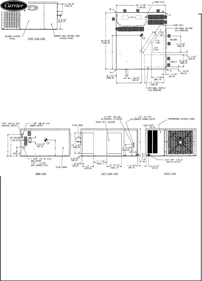
Base unit dimensions
48SS018-042 WITHOUT OPTIONAL BASE RAIL
REQ'D CLEARANCES FOR SERVICING. in. (mm) |
|
|
|
|
||
Duct panel . . . . . . . . . . . . . . . . . . . |
. |
. |
. . . 0 |
|||
Unit top . . . . . . . . . . . . . . . . . . . . . |
. |
|
. 36 (914) |
|||
Side opposite ducts . . . . . . . . . . . . . . . . |
. |
|
. 36 (914) |
|||
Compressor access . . . . . . . . . . . . . . . . |
. |
|
. 36 (914) |
|||
(Except for NEC requirements) |
|
|
|
|||
REQ'D CLEARANCES TO COMBUSTIBLE MAT'L. in. (mm) |
|
|
|
|||
|
|
|
|
|
||
Maximum extension of overhangs . . . . . . . . . . |
. |
. 48 (1219) |
||||
Unit top . . . . . . . . . . . . . . . . . . . . . |
. |
|
. 14 (356) |
|||
Duct side of unit . . . . . . . . . . . . . . . . . |
. |
. . 2 (51) |
||||
Side opposite ducts . . . . . . . . . . . . . . . . |
. |
|
. 14 (356) |
|||
Bottom of unit . . . . . . . . . . . . . . . . . . |
. |
. |
. . . 0 |
|||
Flue panel . . . . . . . . . . . . . . . . . . . . |
. |
|
. 36 (914) |
|||
NEC REQ'D CLEARANCES. in. (mm) |
|
|
|
|||
|
. |
. 42 (1067) |
||||
Between units, control box side . . |
. . . . . . . . . |
|||||
Unit and ungrounded surfaces, control box side . . . . . |
. |
|
. 36 (914) |
|||
Unit and block or concrete walls and other grounded |
|
|
|
|||
surfaces, control box side . . . . . . . . . . . . . |
. |
. 42 (1067) |
||||
|
ELECTRICAL |
UNIT WEIGHT |
|
CORNER WEIGHT |
|
UNIT HEIGHT |
|||
UNIT |
|
|
(lb/kg) |
|
(in./mm) |
||||
|
|
|
|
|
|||||
|
CHARACTERISTICS |
|
|
|
|
|
|
|
|
|
lb |
kg |
A |
B |
|
C |
D |
E |
|
|
|
|
|||||||
48SS180040 |
208/230-1-60 |
272 |
123 |
81/37 |
62/28 |
|
76/35 |
53/24 |
24.1/613 |
48SS024040 |
208/230-1-60 |
303 |
138 |
97/44 |
43/20 |
|
123/56 |
40/18 |
24.1/613 |
48SS024060 |
208/230-1-60 |
315 |
143 |
100/45 |
46/21 |
|
126/57 |
43/20 |
24.1/613 |
48SS030040 |
208/230-1-60, 208/230-3-60 |
320 |
145 |
100/45 |
47/21 |
|
126/57 |
47/21 |
24.1/613 |
48SS030060/080 |
208/230-1-60, 208/230-3-60 |
324 |
147 |
94/43 |
63/29 |
|
115/52 |
52/24 |
24.1/613 |
48SS036060/080 |
208/230-1-60, 208/230-3-60, 460-3-60 |
336 |
153 |
86/39 |
76/35 |
|
111/50 |
63/29 |
24.1/613 |
48SS036100/120 |
208/230-1-60, 208/230-3-60, 460-3-60 |
348 |
158 |
89/40 |
79/36 |
|
114/52 |
66/30 |
24.1/613 |
48SS042060/080 |
208/230-1-60, 208/230-3-60, 460-3-60 |
375 |
170 |
95/43 |
86/39 |
|
119/54 |
75/34 |
28.1/714 |
48SS042100/120 |
208/230-1-60, 208/230-3-60, 460-3-60 |
387 |
176 |
98/45 |
89/40 |
|
122/55 |
78/35 |
28.1/714 |
UNIT |
F |
G |
CENTER OF GRAVITY in./mm |
|||
|
in./mm |
in./mm |
X |
Y |
Z |
|
48SS018040 |
|
|
25.07/637 |
20.59/523 |
|
|
48SS024040 |
|
|
27.07/688 |
23.35/593 |
|
|
48SS024060 |
|
|
26.98/685 |
23.27/591 |
|
|
48SS030040 |
169¤16/420.7 |
1815¤16/481.0 |
26.71/678 |
23.46/596 |
10.85/276 |
|
48SS030060/080 |
|
|
27.15/689 |
22.36/568 |
|
|
48SS036060/080 |
|
|
27.50/698 |
22.48/571 |
|
|
48SS036100/120 |
|
|
27.40/696 |
22.44/570 |
|
|
48SS042060/080 |
209¤16/522.3 |
2215¤16/582.6 |
27.01/686 |
22.44/570 |
12.7/321 |
|
48SS042100/120 |
26.94/684 |
22.44/570 |
||||
|
|
|
||||
|
|
LEGEND |
|
|
|
CG |
Ð |
Center of Gravity |
MAT'L |
Ð |
Material |
COND |
Ð Condenser |
NEC |
Ð National Electrical Code |
||
LV |
Ð |
Low Voltage |
REQ'D |
Ð |
Required |
NOTES:
1.Clearances must be maintained to prevent recirculation of air from outdoor-fan discharge.
2.Adequate clearance around air openings into combustion chamber must be provided.
8

48SS018-042 WITH OPTIONAL BASE RAIL
REQ'D CLEARANCES FOR SERVICING. in. (mm) |
|
|
|
|
|
Duct panel . . . . . . . . . . . . . . . . . . |
. |
. |
. . . . 0 |
||
Unit top . . . . . . . . . . . . . . . . . . . |
. |
. |
. 36 (914) |
||
Side opposite ducts . . . . . . . . . . . . . . |
. |
. |
. 36 (914) |
||
Compressor access . . . . . . . . . . . . . . |
. |
. |
. 36 (914) |
||
(Except for NEC requirements) |
|
|
|
|
|
REQ'D CLEARANCES TO COMBUSTIBLE MAT'L. in. (mm) |
|||||
|
|
|
|
|
|
Maximum extension of overhangs . . . . . . . . . |
. |
|
. 48 (1219) |
||
Unit top . . . . . . . . . . . . . . . . . . . |
. |
. |
. 14 (356) |
||
Duct side of unit . . . . . . . . . . . . . . . . |
. |
. |
. . 2 (51) |
||
Side opposite ducts . . . . . . . . . . . . . . |
. |
. |
. 14 (356) |
||
Bottom of unit . . . . . . . . . . . . . . . . . . . . . . . 0
Flue panel . . . . . . . . . . . . . . . . . . . . . 36 (914)
NEC REQ'D CLEARANCES. in. (mm) |
|
|
|
Between units, control box side . . . . . . . . . . . |
. 42 |
(1067) |
|
Unit and ungrounded surfaces, control box side . . . . |
. . 36 (914) |
||
Unit and block or concrete walls and other grounded |
|
|
|
surfaces, control box side . . . . . . . . . . . . . |
. 42 |
(1067) |
|
|
ELECTRICAL |
UNIT WEIGHT |
|
CORNER WEIGHT |
|
UNIT HEIGHT |
|||
UNIT |
|
|
(lb/kg) |
|
(in./mm) |
||||
CHARACTERISTICS |
|
|
|
|
|
||||
|
|
lb |
kg |
A |
B |
|
C |
D |
E |
48SS018040 |
208/230-1-60 |
296 |
135 |
87/40 |
68/31 |
|
82/37 |
59/27 |
27.4/697 |
48SS024040 |
208/230-1-60 |
327 |
149 |
103/47 |
49/22 |
|
129/59 |
46/21 |
27.4/697 |
48SS024060 |
208/230-1-60 |
339 |
155 |
106/48 |
52/24 |
|
132/60 |
49/22 |
27.4/697 |
48SS030040 |
208/230-1-60, 208/230-3-60 |
344 |
157 |
106/48 |
53/24 |
|
132/60 |
53/24 |
27.4/697 |
48SS030060/080 |
208/230-1-60, 208/230-3-60 |
356 |
162 |
102/46 |
71/32 |
|
123/56 |
60/27 |
27.4/697 |
48SS036060/080 |
208/230-1-60, 208/230-3-60, 460-3-60 |
360 |
164 |
92/42 |
82/37 |
|
117/53 |
69/31 |
27.4/697 |
48SS036100/120 |
208/230-1-60, 208/230-3-60, 460-3-60 |
372 |
169 |
95/43 |
85/39 |
|
120/55 |
72/33 |
27.4/697 |
48SS042060/080 |
208/230-1-60, 208/230-3-60, 460-3-60 |
399 |
181 |
101/46 |
92/42 |
|
125/57 |
81/37 |
31.4/798 |
48SS042100/120 |
208/230-1-60, 208/230-3-60, 460-3-60 |
411 |
187 |
104/47 |
95/43 |
|
128/58 |
84/38 |
31.4/798 |
UNIT |
F |
G |
CENTER OF GRAVITY in./mm |
|||
|
in./mm |
in./mm |
X |
Y |
Z |
|
48SS018040 |
|
|
25.04/636 |
22.72/577 |
|
|
48SS024040 |
|
|
26.90/683.3 |
20.17/512.3 |
|
|
48SS024060 |
|
|
26.82/681.2 |
20.22/513.6 |
|
|
48SS030040 |
197¤8/504.8 |
221¤4/565.4 |
26.57/674.9 |
20.1/ 509.3 |
13.16/334.3 |
|
48SS030060/080 |
|
|
26.93/684 |
21.1/535.4 |
|
|
48SS036060/080 |
|
|
27.31/693.7 |
21.0/532.6 |
|
|
48SS036100/120 |
|
|
27.23/691.6 |
21.0/533.1 |
|
|
48SS042060/080 |
237¤8/606.4 |
261¤4/666.8 |
26.87/682.5 |
21.0/533.1 |
14.96/380 |
|
48SS042100/120 |
26.81/681 |
21.0/533.7 |
||||
|
|
|
||||
|
|
LEGEND |
|
|
|
CG |
Ð |
Center of Gravity |
MAT'L |
Ð |
Material |
COND |
Ð |
Condenser |
NEC |
Ð |
National Electrical Code |
LV |
Ð |
Low Voltage |
REQ'D |
Ð |
Required |
NOTES:
1.Clearances must be maintained to prevent recirculation of air from outdoor-fan discharge.
2.Adequate clearance around air openings into combustion chamber must be provided.
9
 Loading...