


48MA/50ME016-040 Combination Multizone Heating/Cooling Units Gas, Electric, or Glycol Heat
Installation, Start-Up
and Service Instructions
CONTENTS
Page
SAFETY CONSIDERATIONS . . . . . . . . . . . . . . . . . . . 2
INSTALLATION . . . . . . . . . . . . . . . . . . . . . . . . . . . . . 2-34
General . . . . . . . . . . . . . . . . . . . . . . . . . . . . . . . . . . . . . . 2
Unit Clearances . . . . . . . . . . . . . . . . . . . . . . . . . . . . . . 2
Roof Curb . . . . . . . . . . . . . . . . . . . . . . . . . . . . . . . . . . . 2
Roof Openings . . . . . . . . . . . . . . . . . . . . . . . . . . . . . . . 2
Rigging Unit . . . . . . . . . . . . . . . . . . . . . . . . . . . . . . . . . 5
Unit Positioning . . . . . . . . . . . . . . . . . . . . . . . . . . . . . . 5
Removing Shipping Shields . . . . . . . . . . . . . . . . . . 5
Field-Fabricated Ductwork . . . . . . . . . . . . . . . . . . . . 5
Condensate Drains . . . . . . . . . . . . . . . . . . . . . . . . . . . 9
Gas Piping (48MA) . . . . . . . . . . . . . . . . . . . . . . . . . . . 9
Optional Glycol Connections (50ME) . . . . . . . . . 10
Field Power Supply Wiring . . . . . . . . . . . . . . . . . . 10
· UNIT COMMON FEED MINIMUM CIRCUIT AMPS
Field Control Wiring . . . . . . . . . . . . . . . . . . . . . . . . . 14
·ZONE THERMOSTATS
·ZONE MODULE CONNECTIONS
·ACCESSORY REMOTE CONTROL PANEL
Reheat Humidity Control . . . . . . . . . . . . . . . . . . . . 34
Optional Economizer . . . . . . . . . . . . . . . . . . . . . . . . 34
Optional Exhaust Damper . . . . . . . . . . . . . . . . . . . 34
START-UP . . . . . . . . . . . . . . . . . . . . . . . . . . . . . . . . 34-39
Evaporator Fan . . . . . . . . . . . . . . . . . . . . . . . . . . . . . 34
Compressor Rail Shipping Bolts . . . . . . . . . . . . . 34
Refrigerant Valves . . . . . . . . . . . . . . . . . . . . . . . . . . 34
Zone Module Gas Valves (48MA) . . . . . . . . . . . . . 34
Gas Heat Lighting Procedure (48MA) . . . . . . . . . 35
· TO SHUT OFF GAS HEAT
Intermittant Pilots (48MA) . . . . . . . . . . . . . . . . . . . 35
·ADJUSTMENT
·PRESSURE ADJUSTMENT (NATURAL GAS)
Main Burner Adjustment (48MA) . . . . . . . . . . . . . 36
·ORIFICE ALIGNMENT
·PRIMARY AIR ADJUSTMENT
Outdoor-Air Thermostat Adjustment
(50ME With Electric Heat) . . . . . . . . . . . . . . . . . . 36
·UNITS WITH 2-ELEMENT HEATERS
·UNITS WITH 3-ELEMENT HEATERS
Optional Glycol Heating Coils . . . . . . . . . . . . . . . . 38
Zone Air¯ow Adjustment . . . . . . . . . . . . . . . . . . . . 38
Sequence of Operation . . . . . . . . . . . . . . . . . . . . . 38
·COOLING
·HEATING (48MA)
·HEATING (50ME WITH ELECTRIC HEAT)
·HEATING (50ME WITH GLYCOL HEATING COILS)
·OUTDOOR-AIR DAMPER
SERVICE . . . . . . . . . . . . . . . . . . . . . . . . . . . . . . . . . . 39-43
Cabinet Panels and Grilles . . . . . . . . . . . . . . . . . . 39
·SIDE PANELS
·TOP PANELS
·HEATER ACCESS PANELS
Cleaning . . . . . . . . . . . . . . . . . . . . . . . . . . . . . . . . . . . . 39
·EVAPORATOR COILS (ZONE COOLING COILS) AND GLYCOL HEATING COILS
·CONDENSER AND OUTDOOR-AIR COOLING COILS
·CONDENSATE DRAINS
·INDOOR-AIR FILTERS
·OUTDOOR-AIR INLET SCREENS
·GAS HEATING SECTION
·COMBUSTION AIR FAN
Air¯ow Switches . . . . . . . . . . . . . . . . . . . . . . . . . . . . 39
·INDOOR AIRFLOW SWITCH (AFS1)
·COMBUSTION AIRFLOW SWITCH (AFS2)
Service Switch . . . . . . . . . . . . . . . . . . . . . . . . . . . . . . 39
Time GuardT Control Circuit . . . . . . . . . . . . . . . . . 39
Capacity Control Pressure Switches (CCP)
(2-Compressor Units Only) . . . . . . . . . . . . . . . . 39
Compressor Oil . . . . . . . . . . . . . . . . . . . . . . . . . . . . . 39
· TO ADD OR REMOVE OIL
Compressor Capacity Control Unloader(s) . . . . 40
·CONTROL SET POINT
·PRESSURE DIFFERENTIAL
Crankcase Heater(s) . . . . . . . . . . . . . . . . . . . . . . . . . 40
Refrigerant Charge . . . . . . . . . . . . . . . . . . . . . . . . . . 40
·NO CHARGE
·LOW CHARGE
Head Pressure Control . . . . . . . . . . . . . . . . . . . . . . 40
·MOTORMASTERt HEAD PRESSURE CONTROL DEVICE
·FAN CYCLING PRESSURESTAT
Condenser Fans . . . . . . . . . . . . . . . . . . . . . . . . . . . . 41
·ADJUSTMENT
·FAN MOTOR REMOVAL
·LUBRICATION
Evaporator Fans and Motor . . . . . . . . . . . . . . . . . . 41
·MOTOR REMOVAL
·FAN SHAFT BEARING REMOVAL
·FAN SPEED ADJUSTMENT
·PULLEY REMOVAL
·PULLEY ALIGNMENT
·BELT TENSION ADJUSTMENT
·LUBRICATION
Forced-Draft Blower (48MA) . . . . . . . . . . . . . . . . . 42
·LUBRICATION
·AIR SHUTTER ADJUSTMENT
Zone Module Transformers . . . . . . . . . . . . . . . . . . 42
Optional Economizer . . . . . . . . . . . . . . . . . . . . . . . . 42
·THERMOSTAT SETTINGS
·DAMPER POSITION
·OPERATION
Optional Exhaust Damper . . . . . . . . . . . . . . . . . . . 42
Replacement Parts . . . . . . . . . . . . . . . . . . . . . . . . . . 42
START-UP CHECKLIST . . . . . . . . . . . . . . . . . . . . . CL-1
Manufacturer reserves the right to discontinue, or change at any time, speci®cations or designs without notice and without incurring obligations.
Book |
1 |
1 |
|
PC 111 |
Catalog No. 564-840 |
Printed in U.S.A. |
Form 48MA/50ME-3SI |
Pg 1 |
4-96 |
Replaces: 48MA/50ME-1SI |
Tab |
1c |
1d |
|
|
|
|
|
|
|
|
|
|
|
|
|
|
|
|
|
|
|

SAFETY CONSIDERATIONS
Installation and servicing of air-conditioning equipment can be hazardous due to system pressure and electrical components. Only trained and quali®ed service personnel should install, repair, or service air-conditioning equipment.
Untrained personnel can perform basic maintenance functions of cleaning coils and ®lters and replacing ®lters. All other operations should be performed by trained service personnel. When working on air-conditioning equipment, observe precautions in the literature, tags and labels attached to the unit, and other safety precautions that may apply.
Follow all safety codes, including ANSI (American National Standards Institute) Z223.1. Wear safety glasses and work gloves. Use quenching cloth for unbrazing operations. Have ®re extinguisher available for all brazing operations.
Before performing service or maintenance operations on unit, turn off main power switch to unit. Electrical shock could cause personal injury.
Do not try to light any appliance. Do not touch any electrical switch; do not use any phone in your building. Immediately call your gas supplier from a neighbor's phone. Follow the gas supplier's instructions. If you cannot reach your gas supplier, call the ®re department.
Do not store or use gasoline or other ¯ammable vapors and liquids in the vicinity of the 48MA unit or any other gas-®red appliance.
Improper installation, adjustment, alteration, service, or maintenance can cause injury or property damage. Refer to this manual. For assistance or additional information, consult a quali®ed installer, service agency, or the gas supplier.
Disconnect gas piping from 48MA unit when leak testing at pressures greater than 0.5 psig. Pressures greater than 0.5 psig will cause gas valve damage resulting in a hazardous condition. If gas valve is subjected to pressure greater than 0.5 psig, it must be replaced. When pressure testing ®eld-supplied gas piping at pressures of 0.5 psig or less, the unit connected to such piping must be isolated by manually closing the gas valve.
INSTALLATION
General Ð Install unit on rooftop, outdoor site only. Install unit, electrical wiring, gas supply line (48MA) and condensate drain lines in accordance with all applicable codes.
Unit Clearances Ð See Fig. 1 and 2 for service and air¯ow clearances. For 48MA gas-®red units, provide not less than 36-in. clearance to combustibles from top and all sides. Keep burner end free from any obstruction.
Locate exit terminals of mechanical draft system (48MA ¯ue outlet) as follows:
·Not less than 12 in. from any opening through which combustion products could enter the building.
·Not less than 2 ft from any adjacent building.
·Not less than 7 ft above grade when unit is adjacent to public walkways.
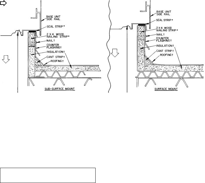
Roof Curb Ð Assemble and install per instructions shipped with this accessory. Information required to ®eld fabricate a roof curb and other curb data are shown in Fig. 3-5.
Install ®eld-supplied insulation, cant strips, roo®ng and counter ¯ashing as required. Seal all curb joints with mastic or other suitable roof cement to keep out moisture. Be sure that run-off pan at compressor end of curb is completely flashed and sealed.
Seal strip (Fig. 3) is shipped with accessory roof curb. Install as described in the roof curb installation instructions. The seal strip compresses under unit weight so that an airtight seal and vibration isolation are provided between unit base and curb.
Roof Openings Ð Except for the compressor and condenser section, roof area under the unit need not be ®lled in as the curb-mounted unit encloses this space. Leaving this roof section open provides ample clearance for ductwork, piping, and power and control wiring.
If the roof area inside curb is to be ®lled in so that roof deck and bottom of base unit can be used as a return-air plenum, any spaces under the curb ¯anges caused by corrugated roo®ng or roof irregularities must be sealed to prevent water seepage. If spaces are not sealed, the negative pressure of return air may draw water under the unit and into the building structure.
If openings are cut in a ®nished roof, provide at least 6-in. space on each of the longer sides of the supply and return air openings. Due to interference from the roof curb structure, this additional clearance may not be possible on the short sides.
2
CONDENSER SECTION AIRFLOW
CONN Ð Connection
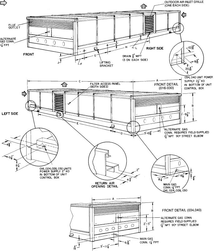
NOTES:
1.Space required for service and air¯ow all around and above unit is 36 inches.
2.For additional information see Fig. 4.
3.Center of gravity is within 6 in. radius of geometric center of unit.
4.Maximum allowable pitch of unit is 1¤2 in. per 10 ft in any direction.
Certi®ed dimension drawings available on request.
UNIT |
|
|
|
|
DIMENSIONS (ft-in.) |
|
|
|
|
||
48MA |
A |
B |
C |
D |
E |
F |
G |
H |
J |
K |
L |
016-030 |
7- 23¤4 |
3-05¤8 |
17-115¤16 |
2-215¤16 |
13-51¤2 |
0- 91¤16 |
2-10 |
7-33¤16 |
0-31¤8 |
0-31¤8 |
0-31¤8 |
034,040 |
7-11 |
3-915¤16* |
21- 91¤16 |
4-25¤8 |
13-51¤2 |
0-111¤16 |
3- 45¤16 |
8-63¤4 |
0-31¤32 |
0-215¤16 |
0-71¤4 |
*Overall height; includes 13¤4-in. for fan guards.
Fig. 1 Ð Base Unit Physical Data and Dimensions; 48MA Units
3
CONDENSER SECTION AIRFLOW
CONN Ð Connection
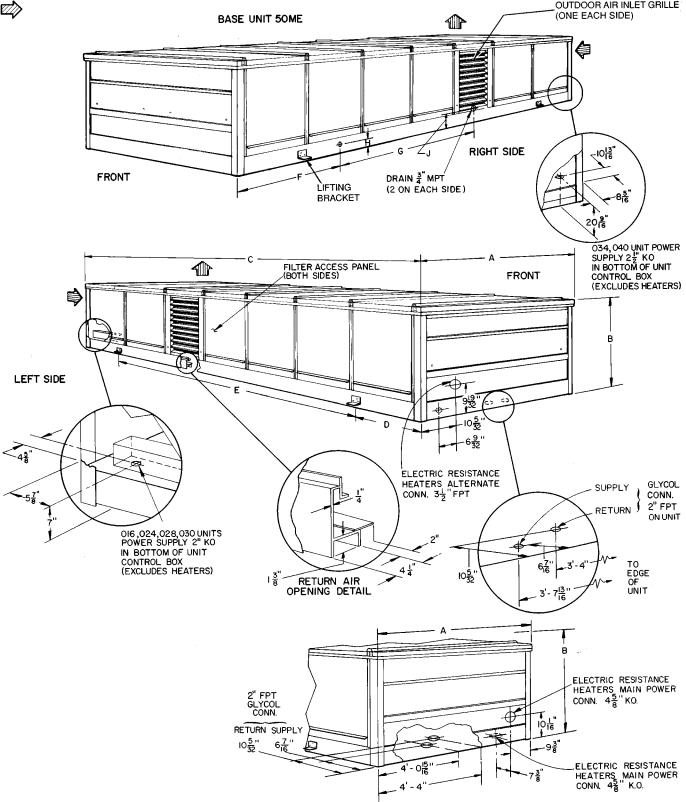
NOTES:
1.Space required for service and air¯ow all around and above unit is 36 inches.
2.For additional information see Fig. 5.
3.Center of gravity is within 6 in. radius of geometric center of unit.
4.Maximum allowable pitch of unit is 1¤2 in. per 10 ft in any direction.
Certi®ed dimension drawings available on request.
UNIT |
|
|
|
DIMENSIONS (ft-in.) |
|
|
|
|
||
50ME |
A |
B |
C |
D |
E |
|
F |
G |
H |
J |
016-030 |
7- 23¤4 |
3-09¤16 |
17-115¤16 |
2-215¤16 |
13-51¤2 |
|
3-71¤16 |
7-33¤16 |
0-31¤8 |
0-31¤8 |
034,040 |
7-11 |
3-915¤16* |
21-91¤16 |
4-25¤8 |
13-51¤2 |
|
4-4 |
8-63¤4 |
0-215¤16 |
0-71¤4 |
*Overall height; includes 13¤4-in. for fan guards.
Fig. 2 Ð Base Unit Physical Data and Dimensions; 50ME Units
4
AIRFLOW
*Factory supplied (with accessory roof curb). ²Field supplied (when using accessory roof curb).
NOTE: Dimensions are in inches.
Fig. 3 Ð Roof Curb Detail
Rigging Unit Ð Inspect unit for shipping damage, and ®le any damage claim immediately with transportation company.
Lift unit with cables and spreader bars, using lifting brackets provided (Fig. 1 and 2). Lift one unit at a time, keep unit upright, and do not drop. Unit weights are given in Table 1. Unit center of gravity is within 6 in. of unit's geometric center. Eyebolts may be removed after unit is in ®nal position.
IMPORTANT: Do not drill or punch holes in unit frame or panels; damage to internal components or wiring may result.
Unit Positioning Ð When lowering unit onto roof curb, do not exceed the out-of-symmetry tolerances given in Fig. 4 and 5. Be sure unit is level or is pitched within speci- ®ed tolerances. Units have drains on both sides and may be pitched to either side.
Removing Shipping Shields (Fig. 6)
1.Remove shield over ¯ue outlet grille (48MA only).
2.Remove shields (sheet metal covers) located in the outdoorair inlet screen tracks behind the louvers. If the screens are removed for this procedure, be sure to replace them before replacing the louvered assembly.
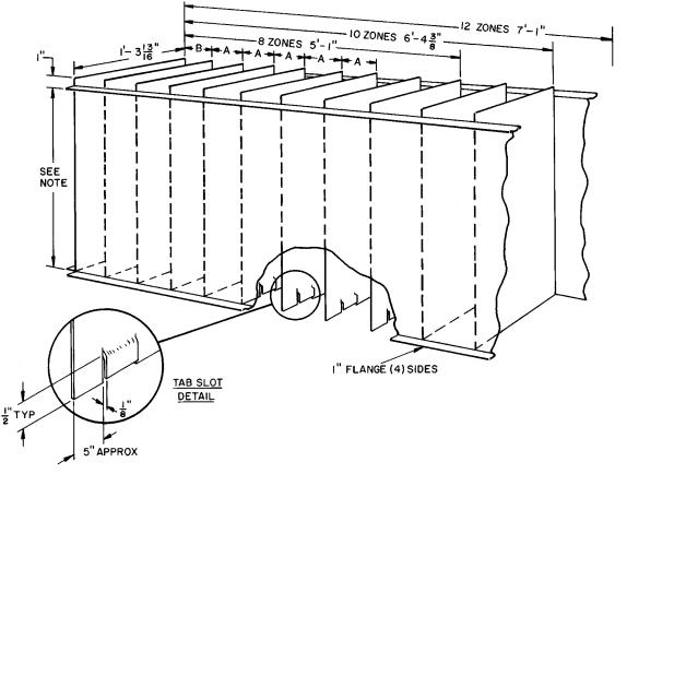
Field-Fabricated Ductwork Ð Supplyand returnair openings are shown in Fig. 4 and 5. To simplify supplyair connection, a zone duct plenum may be ®eld fabricated as shown in Fig. 7. It is recommended that this plenum be installed prior to unit positioning.
It is recommended that the unit be supported on blocks temporarily while the duct plenum is installed, rather than installing the plenum while the unit is suspended. The duct plenum may be installed once the unit is located in its ®nal position, but it is much easier to install the plenum prior to unit ®nal placement.
Zone supply-air duct openings on the base unit have tab slot connections similar to those shown in Fig. 7 except that the end partitions are hemmed. Hem is positioned so that the 1-in. ¯ange at entering end of ®eld-fabricated plenum will force-®t between hem and adjacent unit frame.
Standard ¯exible duct connections between duct plenum and duct system may be used. Follow applicable codes.
Insulate any supply-air ducts passing through unconditioned spaces and cover with a vapor barrier. Separate ducts with insulation if they run parallel for more than 5 ft. This will prevent heat transfer between zones.
Install a manual balancing damper in each zone duct to provide the required zone air¯ow.
The return-air duct connection consists of 4 sheet metal ¯anges as shown in Fig. 1, 2, 4, and 5.
5
Table 1 Ð Physical Data
|
UNIT 48MA/50ME |
|
016 |
024 |
|
028 |
|
030 |
034 |
|
040 |
|
Zone Modules (Quantity) |
|
8 |
8 |
|
10 |
|
10 |
12 |
|
12 |
|
Nominal Cooling Capacity (tons) |
15 |
20 |
|
25 |
|
28 |
30 |
|
37 |
|
|
OPERATING WEIGHT (lb) |
|
|
|
|
|
|
|
|
|
|
|
Base Unit 48MA |
|
3395 |
3815 |
|
4075 |
|
4080 |
5340 |
|
5710 |
|
Base Unit 50ME (with electric heat) |
2995 |
3415 |
|
3675 |
|
3680 |
4900 |
|
5270 |
|
|
Roof Curb |
|
506 |
506 |
|
506 |
|
506 |
630 |
|
630 |
|
REFRIGERANT CHARGE Ð R-22 (lb) |
28 |
32 |
|
43 |
|
43 |
57 |
|
66.1 |
|
|
COMPRESSOR |
|
|
|
Reciprocating Hermetic, 1725 Rpm |
|
|
|
|||
|
No. 1 Type |
|
06DE537 |
06DE824 |
|
06DE537 |
|
06DE537 |
06DE537 |
|
06EE250 |
|
Cylinders...Unloaders |
|
6...2 |
6...2 |
|
6...2 |
|
6...2 |
6...2 |
|
4...1 |
|
No. 2 Type |
|
Ð |
06DA824 |
|
06DA824 |
|
06DA537 |
06DA537 |
|
06EA250 |
|
Cylinders (have no unloaders) |
Ð |
6 |
|
6 |
|
6 |
6 |
|
4 |
|
|
System Oil Charge (pints) |
|
11 |
18 |
|
18 |
|
18 |
18 |
|
31 |
|
Unloader Settings (psig) |
Loads |
|
|
|
Compressor No. 1 Only |
|
|
|
||
|
Unloader No. 2 |
|
|
71.0 ± 1.5 |
|
|
|
|
Ð |
||
|
Unloads |
|
|
57.5 ± 2.5 |
|
|
|
|
Ð |
||
|
|
|
|
|
|
|
|
||||
|
Unloader No. 1 |
Loads |
|
|
75.0 ± 1.5 |
|
|
|
|
75.5 ± 1.5 |
|
|
Unloads |
|
|
62.5 ± 2.5 |
|
|
|
|
58.0 ± 2.5 |
||
|
|
|
|
|
|
|
|
||||
|
Capacity Steps (%) |
|
100,67,33 |
100,83,67 |
|
100,80,60 |
|
100,80,60 |
100,83,67 |
|
100,75, |
|
|
50,33,17 |
|
40,20 |
|
40,20 |
50,33,17 |
|
50,25 |
||
|
|
|
|
|
|
|
|||||
|
CONDENSER FANS |
|
|
|
|
Propeller, Direct Drive |
|
|
|
||
|
Motor Hp...Rpm...Frame (NEMA) |
|
|
|
|
|
|
|
|
|
|
|
|
No. 1 |
|
|
|
1...1075...56 (Single phase) |
|
|
|
||
|
|
No. 2 |
|
|
|
1...1140...56 (3 phase) |
|
|
|
||
|
Nominal Cfm |
No. 3 |
Ð |
Ð |
|
Ð |
|
Ð |
1...1140...56 (3 phase) |
||
|
|
16,500 |
15,000 |
|
15,000 |
|
15,000 |
24,000 |
|
23,000 |
|
|
EVAPORATOR FANS* |
|
|
|
|
Centrifugal, Belt Drive |
|
|
|
||
|
Number...Size (in.) |
|
2...15 × 15 |
2...15 × 15 |
|
2...15 × 15 |
|
2...15 × 15 |
3...15 × 9 |
|
3...15 × 9 |
|
Cfm (Nominal) |
Std |
6000 |
8000 |
|
10,000 |
|
10,000 |
12,000 |
|
12,000 |
|
Motor Hp...Rpm |
5...1725 |
71¤2...1725 |
|
10...1725 |
|
10...1725 |
15...1725 |
|
15...1725 |
|
|
Alt |
Ð |
Ð |
|
Ð |
|
Ð |
20...1725 |
|
20...1725 |
|
|
Fan Pulley |
|
|
|
|||||||
|
|
|
|
|
|
|
|
|
|
|
|
|
Outside Diameter (in.) |
|
10.6 |
10.6 |
|
8.0 |
|
8.0 |
8.0 |
|
8.0 |
|
Bore (in.) |
Std |
13¤16 |
13¤16 |
|
13¤16 |
|
13¤16 |
111¤16 |
|
111¤16 |
|
Fan Belt Number...Size |
1...3V630 |
1...3V630 |
|
2...3V560 |
|
2...3V560 |
2...3V630 |
|
2...3V630 |
|
|
Alt |
Ð |
Ð |
|
Ð |
|
Ð |
3...3V670 |
|
3...3V670 |
|
|
|
|
|
|
|||||||
|
Motor Pulley |
Std |
|
|
|
Factory Installed |
|
|
|
||
|
Outside Diameter (in.) |
5.3 |
6.0 |
|
5.0 |
|
5.0 |
5.0 |
|
5.0 |
|
|
Alt |
Ð |
Ð |
|
Ð |
|
Ð |
6.0 |
|
6.0 |
|
|
Bore (in.) |
|
|
|
|||||||
|
Std |
11¤8 |
13¤8 |
|
13¤8 |
|
13¤8 |
15¤8 |
|
15¤8 |
|
|
Resulting Fan Rpm |
880 |
995 |
|
1095 |
|
1095 |
1095 |
|
1095 |
|
|
Alt |
Ð |
Ð |
|
Ð |
|
Ð |
1320 |
|
1320 |
|
|
|
|
|
|
|||||||
|
Shaft Center Line Distance (in.) |
18 ± 2.5 |
18 ± 2.5 |
|
18 ± 2.5 |
|
18 ± 2.5 |
21 ± 2.5 |
|
21 ± 2.5 |
|
|
Maximum Fan Rpm |
|
1300 |
1300 |
|
1300 |
|
1300 |
1550 |
|
1550 |
|
CONDENSER COOLING COIL |
|
Thermostatic Expansion Valve, Hot Gas Bypass |
|
|
||||||
|
Face Area (sq ft) |
|
6.8 |
6.8 |
|
6.8 |
|
6.8 |
10.2 |
|
10.2 |
|
Corrugated Fins/in. ...Rows |
13...2 |
13...2 |
|
13...2 |
|
13...2 |
13...2 |
|
13...3 |
|
|
EVAPORATOR COILS (zone) |
|
|
Solenoid Valve and Capillary Tube for each |
|
|
|||||
|
Number...Face Area (sq ft/ea) |
8...2.12 |
8...2.12 |
|
10...2.12 |
|
10...2.12 |
12...2.01 |
|
12...2.01 |
|
|
Corrugated Fins/in. ...Rows |
13...3 |
13...3 |
|
13...3 |
|
13...3 |
12...3 |
|
15...3 |
|
|
HEATING SECTION (48MA) |
|
|
One Heat Assembly in Each Zone Module |
|
|
|||||
|
Rise Range |
Total |
|
|
|
25 F to 55 F at 0.75 in. wg ESP |
|
|
|
||
|
Input (1000 Btuh) |
432 |
432 |
|
540 |
|
540 |
648 |
|
648 |
|
|
Each Module |
54 |
54 |
|
54 |
|
54 |
54 |
|
54 |
|
|
|
|
|
|
|||||||
|
Bonnet Cap.² (1000 Btuh) |
Total |
324 |
324 |
|
405 |
|
405 |
486 |
|
486 |
|
Each Module |
40.5 |
40.5 |
|
40.5 |
|
40.5 |
40.5 |
|
40.5 |
|
|
Burner Spud Qty...Size |
|
2...38 |
2...38 |
|
2...38 |
|
2...38 |
2...38 |
|
2...38 |
|
OPTIONAL HEATING SECTION (50ME Electric) |
|
|
|
|
|
|
|
|
|
|
|
Electric Heaters |
|
|
Nichrome, Open-Wire Resistance Element in Each Zone Module |
|||||||
|
Qty...Elements (each)** |
|
8...2 or 3 |
8...2 or 3 |
|
10...2 or 3 |
|
10...2 or 3 |
12...2 or 3 |
|
12...2 or 3 |
|
OPTIONAL HEATING SECTION |
|
|
One Heating Coil in Each Zone Module |
|
|
|||||
|
(50ME Glycol Coil) |
|
|
|
|
|
|||||
|
|
|
|
|
|
|
|
|
|
|
|
|
Maximum Allowable Inlet Temperature (F) |
|
|
|
|
200 |
|
|
|
||
|
Maximum Allowable Flow, Each Coil (Gpm) |
|
|
|
|
6 |
|
|
|
|
|
|
Solution Mixture |
|
|
|
|
20% Glycol |
|
|
|
||
|
Maximum Allowable Working Pressure (Psig) |
|
|
|
|
30 |
|
|
|
||
|
Total Internal Volume (Gal) |
|
2.61 |
2.61 |
|
3.15 |
|
3.15 |
3.76 |
|
3.76 |
|
PRESSURE SWITCHES |
Cutout |
|
|
|
|
29 ± 5 |
|
|
|
|
|
Low-Pressure (Psig) |
|
|
|
|
|
|
|
|||
|
Cut-in |
|
|
|
|
39 ± 5 |
|
|
|
||
|
|
|
|
|
|
|
|
|
|||
|
High-Pressure (Psig) |
Cutout |
|
|
400 ± 5 |
|
|
|
|||
|
Cut-in |
|
|
300 ± 5 |
|
|
|
||||
|
|
|
|
|
|
|
|||||
|
Indoor Air¯ow Switch (AFS1) |
|
|
|
|
|
|
|
|
|
|
|
Factory Setting (cfm) |
|
|
|
6000 |
|
|
|
9000 |
||
|
Adjustment Range (cfm) |
|
|
4000-6000 |
|
|
6000-9000 |
||||
|
INDOOR AIR FILTERS |
|
|
|
|
|
|
|
|
|
|
|
Standard Qty...Size (in.) |
|
|
|
12...20 × 25 × 2 |
|
|
|
|||
|
High Efficiency (optional) |
|
|
|
|
12...20 × 2 5 × 2 (36.5% Efficient) |
|
|
|
||
|
Qty...Size (in.) |
|
|
|
|
|
|
|
|||
|
|
|
|
|
|
|
|
|
|
|
|
|
OUTDOOR AIR FILTERS |
|
|
|
|
|
|
|
|
|
|
|
Qty...Size (in.) |
|
|
2...20 × 25 × 1 |
|
|
2...32 × 35 × 1 |
||||
|
LEGEND |
ESP Ð |
External Static Pressure |
NEMA Ð |
National Electrical Manufacturers Association |
*Standard unit shipped with standard motor, pulley, and belt(s); alternate unit shipped with alternate motor, pulley, and belt(s).
²The heating efficiency rating is a product thermal efficiency rating determined under continuous operating conditions independent of any installed system. **See Field Power Supply Wiring section on page 10 and Table 4 for details.
6

EVAPORATOR (ZONE MODULE) AIRFLOW
CONN Ð Connection
*Not used on 48MA016,024 (8 zone module units).
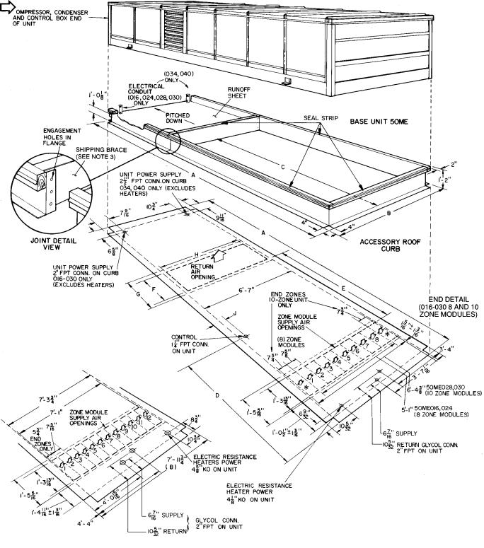
NOTES:
1. For additional information, see Table 1 and Fig. 1.
2. Maximum allowable unit pitch is 1¤2 in. per 10 ft in any direction. 3. Remove shipping brace before assembling curb section (location
shown).
UNIT |
|
|
|
DIMENSIONS (ft-in.) |
|
|
|
||
48MA |
A |
B |
C |
D |
E |
F |
G |
H |
J |
016-030 |
18-21¤8 |
7- 3 |
11-9 |
5-61¤4 |
7-27¤8 |
1-109¤16 |
2-29¤16 |
6-03¤8 |
0- 71¤2 |
034,040 |
21-97¤8 |
7-113¤4 |
14-13¤4 |
6-77¤16 |
8-43¤16 |
2- 91¤8 |
3-1 |
6-81¤2 |
0-105¤16 |
Fig. 4 Ð Roof Curb Physical Data and Dimensions; 48MA Units
7
END DETAIL
(034,044 12-ZONE MODULES)
EVAPORATOR (ZONE MODULE) AIRFLOW
CONN Ð Connection
*Not used on 50ME016,024 (8 zone module units).
NOTES:
1.For additional information, see Table 1 and Fig. 2.
2.Maximum allowable unit pitch is 1¤2 in. per 10 ft in any direction.
3.Remove shipping brace before assembling curb section (location shown).
UNIT |
|
|
|
DIMENSIONS (ft-in.) |
|
|
|
||
50ME |
A |
B |
C |
D |
E |
F |
G |
H |
J |
016-030 |
18-21¤8 |
7- 3 |
11-9 |
5-61¤4 |
7-27¤8 |
1-109¤16 |
2-29¤16 |
6-03¤8 |
0- 71¤2 |
034,040 |
21-97¤8 |
7-113¤4 |
14-13¤4 |
6-77¤16 |
8-43¤16 |
2- 91¤8 |
3-1 |
6-81¤2 |
0-105¤16 |
Fig. 5 Ð Roof Curb Physical Data and Dimensions; 50ME Units
8
Condensate Drains Ð Pipe nipples covered with foam rubber insulation are shipped in unit return air ®lter section (6 nipples in units 48MA, 4 nipples in units 50ME). Install a nipple in each drain connection on both sides of unit. See Fig. 1 and 2 for drain locations. Be sure foam rubber seals space between nipple and base rail opening to prevent rain leaks.
Connect a drain line to drain connection under outdoor air inlet grilles on both sides of unit. These drains need not be trapped.
Install a trapped drain line on remaining connections on lowest side of unit depending on unit pitch. If unit is level, a trapped drain may be installed at each connection if desired. Cap or plug unused connections on high side of unit to prevent air¯ow between unit interior and outdoors.
OUTDOOR AIR INLET |
|
|
(ONE ON EACH SIDE OF UNIT) |
FLUE OUTLET |
|
SHIPPING SHIELD |
||
COVER |
||
(BEHIND LOUVERS) |
||
(48MA ONLY) |
||
|
Fig. 6 Ð Shipping Shield Locations
(016-030 Units Shown)
Do not interconnect drains. Make each trap a minimum of 4 in. deep. Insulate trap against freeze-up or use ¯exible material.
Gas Piping (48MA) Ð Unit is equipped for use with type of gas shown on nameplate. Refer to latest edition of ANSI Z223.1. Unit main gas connection and alternate gas connection locations are shown in Fig. 1, 4, and 8. Do not use gas supply pipe smaller than unit gas connection. Maximum allowable natural gas supply pressure is 10.0 in. wg; minimum allowable natural gas supply pressure for full rate input is 5.0 in. wg.
Pitch pipe 1¤4 in. per 15 ft. Pitch all horizontal pipe runs upward to risers and from risers upward to meter. Install a dirt and moisture pocket (drip leg) at each section of vertical pipe run. Use only ground joint unions to ensure leakfree joints. Use only pipe joint compounds that are resistant to the action of lique®ed petroleum gases.
NOTE: Dimension to suit job requirements. Twelve inches will bring duct plenum to bottom of roof curb.
DIMENSIONS (in.)
UNIT |
016,024 |
028,030 |
034,040 |
|
48MA,50ME |
||||
|
|
|
||
A* |
75¤8 |
75¤8 |
75¤16 |
|
B* |
75¤8 |
73¤4 |
53¤4 |
*Typical; both ends.
Fig. 7 Ð Field-Fabricated Zone Duct Plenum Detail
9
*Shutoff valve not used except where required by code.
Properly cap any gas connection not being used.
Fig. 8 Ð Suggested Gas Piping (48MA)
Unit has factory-installed gas shutoff valves. Install gas shutoff valve external to unit if required by code (Fig. 8). After piping is complete, pressurize gas line and check for leaks with soap and water solution.
Do not use an open ¯ame when checking for gas leaks.
Optional Glycol Connections (50ME) Ð Each zone module has its own glycol heating coil and 115-v solenoid valve. Heating coils are connected in parallel to common supply and return manifolds. Supply manifolds are equipped with bleed cocks. Supply and return connections are shown in Fig. 2 and 5. Unit does not have internal pressure relief for part-load operation. Maximum allowable system working pressure is 30 psig. Unit ratings are based on 20% glycol solutions. Install solution supply apparatus in accordance with application requirements, and mix glycol solution percentage in accordance with glycol manufacturer's recommendations. Freeze-up protection is not factory installed.
Field Power Supply Wiring Ð When installed, unit must be electrically grounded in accordance with local codes or, in the absence of local codes, with the National Electrical Code (NEC).
Unit has a circuit breaker for each compressor, each fan motor, and for each 50ME electric resistance heater assembly (if unit is so equipped). If required by local code, provide an additional disconnect switch in accordance with code being followed.
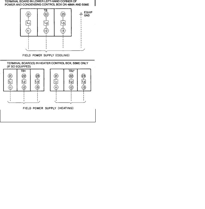
All units have a main power supply terminal board in the power and condensing control box. The electric resistance heater power supply terminal board(s) (if unit is so equipped) on 50ME units is located in the heater control box at front of unit. See Fig. 2, 5, and 9.
All terminal boards are suitable for use with copper or aluminum wire.
Connect electrical conduit (a threaded pipe nipple) shipped with unit to threaded ®tting in roof curb and bottom of main power and condensing section control box. Route main power wires through conduit to terminal board in box as shown on unit label wiring diagram and in Fig. 9.
When installing 48MA,50ME040 units with optional 20-hp motor, the electrical conduit interconnecting the curb and control box power wire openings will not accommodate aluminum wire of the size that may be required. If aluminum wire cannot be accommodated, an external transition box and short lengths of no. 300 kcmil, 75 C copper wire from the transition box to the unit main power connection are recommended.
Voltage to compressor terminals during compressor operation must be within voltage range indicated on unit nameplate. Phases must be balanced within 2%.
|
LEGEND |
EQUIP |
Ð Equipment |
GND |
Ð Ground |
TB |
Ð Terminal Board |
*208/230 v units only.
Fig. 9 Ð Field Power Supply Details
10
Use the following formula to determine the percent voltage imbalance.
% Voltage Imbalance:
= 100 × |
max voltage deviation from average voltage |
|
average voltage |
||
|
EXAMPLE: Supply voltage is 460-3-60.
AB = 452 v
BC = 464 v
AC = 455 v
452 + 464 + 455
Average Voltage =
3
1371
=
3
= 457
Determine maximum deviation from average voltage.
(AB) 457 − 45 2 = 5 v (BC) 464 − 45 7 = 7 v (AC) 457 − 45 5 = 2 v
Maximum deviation is 7 v.
Determine percent voltage imbalance:
7
% Voltage Imbalance = 100 x
457
= 1.53%
This amount of phase imbalance is satisfactory as it is below the maximum allowable 2%.
IMPORTANT: If the supply voltage phase imbalance is more than 2%, contact your local electric utility company immediately.
Unit failure as a result of operation on improper line voltage or excessive phase imbalance constitutes abuse and may cause damage to electrical components. See Tables 2-5 for unit, electric heater, and 50ME electrical application electrical data.
Each 50ME electric heat unit is ®tted with a heating lockout circuit (if equipped with optional heat). If any zone module is operating on mechanical cooling (compressor is operating), the heating element in each zone module is locked out and cannot be energized.
On 50ME units, cooling power supply wires and electric heater power supply wires (if applicable) must be sized according to the cooling MCA (Minimum Circuit Amps) values and heating MCA values shown on unit nameplate and in Tables 3-5. These wires may be powered by a common power supply (i.e., a pull-box junction), if desired. The common power supply wires from the main power source to the junction must be sized according to the common MCA values shown in Table 5.
UNIT COMMON FEED MINIMUM CIRCUIT AMPS Ð The unit common feed MCA is calculated on the basis of either: the sum of the cooling MCA plus 1¤2 heating MCA on units with 2 heating elements per zone module (or 2¤3 heating MCA on units with 3 heating elements per zone module) or the sum of the evaporator fan motor full load amps, per NEC, plus the full heating MCA, whichever is larger. Field wiring must conform to NEC limitations for Type T wire.
Table 2 Ð Unit 48MA Electrical Data
UNIT |
Voltage |
VOLTAGE |
COMP |
COMP |
|
OFM |
|
COMBUSTION |
|
IFM |
POWER |
|||||
RANGE |
NO. 1 |
NO. 2 |
|
FLA |
|
FAN MOTOR |
|
SUPPLY |
||||||||
48MA |
(3 Ph, 60 Hz) |
|
|
|
|
|
||||||||||
Min |
Max |
RLA |
LRA |
RLA |
LRA |
No. 1 |
No. 2 |
No. 3 |
FLA |
Hp |
|
FLA |
MCA |
MOCP |
||
|
|
|
||||||||||||||
|
208/230 |
187 |
254 |
63.6 |
266 |
|
|
|
6.6 |
|
|
|
|
16.2 |
109.6 |
125 |
016 |
460 |
414 |
508 |
28.6 |
120 |
Ð |
Ð |
6.2 |
3.0 |
Ð |
1.8 |
5 |
|
6.6 |
49.8 |
60 |
|
575 |
518 |
632 |
22.8 |
96 |
|
|
|
2.4 |
|
|
|
|
5.6 |
39.8 |
45 |
|
208/230 |
187 |
254 |
44.4 |
170 |
44.4 |
170 |
|
6.6 |
|
|
|
|
24.2 |
137.5 |
150 |
024 |
460 |
414 |
508 |
19.9 |
77 |
19.9 |
77 |
6.2 |
3.0 |
Ð |
1.8 |
7.5 |
|
11.0 |
62.2 |
70 |
|
575 |
518 |
632 |
15.7 |
62 |
15.7 |
62 |
|
2.4 |
|
|
|
|
9.0 |
49.4 |
60 |
|
208/230 |
187 |
254 |
63.6 |
266 |
44.4 |
170 |
|
6.6 |
|
|
|
|
30.8 |
168.1 |
200 |
028 |
460 |
414 |
508 |
28.6 |
120 |
19.9 |
77 |
6.2 |
3.0 |
Ð |
1.8 |
10 |
|
13.0 |
76.1 |
90 |
|
575 |
518 |
632 |
22.8 |
96 |
15.7 |
62 |
|
2.4 |
|
|
|
|
10.5 |
60.4 |
70 |
|
208/230 |
187 |
254 |
63.6 |
266 |
63.6 |
266 |
|
6.6 |
|
|
|
|
30.8 |
187.3 |
200 |
030 |
460 |
414 |
508 |
28.6 |
120 |
28.6 |
120 |
6.2 |
3.0 |
Ð |
1.8 |
10 |
|
13.0 |
84.5 |
100 |
|
575 |
518 |
632 |
22.8 |
96 |
22.8 |
96 |
|
2.4 |
|
|
|
|
10.5 |
67.5 |
90 |
|
208/230 |
187 |
254 |
63.6 |
266 |
63.6 |
266 |
|
6.6 |
6.6 |
|
15 |
|
46.2 |
210.8 |
225 |
|
|
|
20 |
|
61.0 |
224.6 |
250 |
|||||||||
|
|
|
|
|
|
|
|
|
|
|
|
|
||||
034 |
460 |
414 |
508 |
28.6 |
120 |
28.6 |
120 |
6.2 |
3.0 |
3.0 |
1.8 |
15 |
|
21.0 |
94.5 |
100 |
20 |
|
26.6 |
100.5 |
125 |
||||||||||||
|
|
|
|
|
|
|
|
|
|
|
|
|
||||
|
575 |
518 |
632 |
22.8 |
96 |
22.8 |
96 |
|
2.4 |
2.4 |
|
15 |
|
16.0 |
75.6 |
90 |
|
|
|
20 |
|
21.3 |
80.6 |
100 |
|||||||||
|
|
|
|
|
|
|
|
|
|
|
|
|
||||
|
208/230 |
187 |
254 |
80.0 |
345 |
80.0 |
345 |
|
6.6 |
6.6 |
|
15 |
|
46.2 |
247.7 |
300 |
|
|
|
20 |
|
61.0 |
261.5 |
300 |
|||||||||
|
|
|
|
|
|
|
|
|
|
|
|
|
||||
040 |
460 |
414 |
508 |
38.5 |
150 |
38.5 |
150 |
6.2 |
3.0 |
3.0 |
1.8 |
15 |
|
21.0 |
116.7 |
150 |
20 |
|
27.0 |
122.7 |
150 |
||||||||||||
|
|
|
|
|
|
|
|
|
|
|
|
|
||||
|
575 |
518 |
632 |
31.4 |
120 |
31.4 |
120 |
|
2.4 |
2.4 |
|
15 |
|
16.0 |
95 |
125 |
|
|
|
20 |
|
21.3 |
100 |
125 |
|||||||||
|
|
|
|
|
|
|
|
|
|
|
|
|
||||
|
LEGEND |
COMP Ð Compressor |
|
FLA |
Ð Full Load Amps |
IFM |
Ð Indoor (Evaporator) Fan Motor |
LRA |
Ð Locked Rotor Amps |
MCA |
Ð Minimum Circuit Amps |
MOCP Ð Maximum Overcurrent Protection
OFM |
Ð |
Outdoor (Condenser) Fan Motor |
RLA |
Ð |
Rated Load Amps |
NOTES:
1.Combustion air fan is a 115-1-60 motor on all units.
2.Condenser fan motor no. 1 is a 208/230-1-60 speed control motor on all units.
11
Table 3 Ð Unit 50ME Electrical Data
UNIT |
VOLTAGE |
VOLTAGE |
COMP |
COMP |
|
OFM |
|
|
IFM |
POWER |
|||||
RANGE |
NO. 1 |
NO. 2 |
|
FLA |
|
|
SUPPLY |
||||||||
50ME |
(3 Ph, 60 Hz) |
|
|
|
|
|
|||||||||
Min |
Max |
RLA |
LRA |
RLA |
LRA |
No. 1 |
No. 2 |
No. 3 |
Hp |
|
FLA |
MCA |
MOCP |
||
|
|
|
|||||||||||||
|
208/230 |
187 |
254 |
63.6 |
266 |
|
|
|
6.6 |
|
|
|
16.2 |
109.6 |
125 |
016 |
460 |
414 |
508 |
28.6 |
120 |
Ð |
Ð |
6.2 |
3.0 |
Ð |
5 |
|
6.6 |
49.5 |
60 |
|
575 |
518 |
632 |
22.8 |
96 |
|
|
|
2.4 |
|
|
|
5.6 |
39.6 |
45 |
|
208/230 |
187 |
254 |
44.4 |
170 |
44.4 |
170 |
|
6.6 |
|
|
|
24.2 |
138.0 |
150 |
024 |
460 |
414 |
508 |
19.9 |
77 |
19.9 |
77 |
6.2 |
3.0 |
Ð |
7.5 |
|
11.0 |
61.9 |
70 |
|
575 |
518 |
632 |
15.7 |
62 |
15.7 |
62 |
|
2.4 |
|
|
|
9.0 |
49.2 |
60 |
|
208/230 |
187 |
254 |
63.6 |
266 |
44.4 |
170 |
|
6.6 |
|
|
|
30.8 |
168.9 |
200 |
028 |
460 |
414 |
508 |
28.6 |
120 |
19.9 |
77 |
6.2 |
3.0 |
Ð |
10 |
|
13.0 |
75.8 |
90 |
|
575 |
518 |
632 |
22.8 |
96 |
15.7 |
62 |
|
2.4 |
|
|
|
10.5 |
60.2 |
70 |
|
208/230 |
187 |
254 |
63.6 |
266 |
63.6 |
266 |
|
6.6 |
|
|
|
30.8 |
188.0 |
200 |
030 |
460 |
414 |
508 |
28.6 |
120 |
28.6 |
120 |
6.2 |
3.0 |
Ð |
10 |
|
13.0 |
84.5 |
100 |
|
575 |
518 |
632 |
22.8 |
96 |
22.8 |
96 |
|
2.4 |
|
|
|
10.5 |
67.3 |
90 |
|
208/230 |
187 |
254 |
63.6 |
266 |
63.6 |
266 |
|
6.6 |
6.6 |
15 |
|
46.0 |
210.8 |
225 |
|
|
20 |
|
61.0 |
224.6 |
250 |
|||||||||
|
|
|
|
|
|
|
|
|
|
|
|
||||
034 |
460 |
414 |
508 |
28.6 |
120 |
28.6 |
120 |
6.2 |
3.0 |
3.0 |
15 |
|
19.8 |
94.5 |
100 |
20 |
|
26.6 |
100.5 |
125 |
|||||||||||
|
|
|
|
|
|
|
|
|
|
|
|
||||
|
575 |
518 |
632 |
22.8 |
96 |
22.8 |
96 |
|
2.4 |
2.4 |
15 |
|
16.0 |
75.6 |
90 |
|
|
20 |
|
21.3 |
80.6 |
100 |
|||||||||
|
|
|
|
|
|
|
|
|
|
|
|
||||
|
208/230 |
187 |
254 |
80.0 |
345 |
80.0 |
345 |
|
6.6 |
6.6 |
15 |
|
46.2 |
247.7 |
300 |
|
|
20 |
|
61.0 |
261.5 |
300 |
|||||||||
|
|
|
|
|
|
|
|
|
|
|
|
||||
040 |
460 |
414 |
508 |
39.3 |
150 |
39.3 |
150 |
6.2 |
3.0 |
3.0 |
15 |
|
19.8 |
118.5 |
150 |
20 |
|
26.6 |
124.5 |
150 |
|||||||||||
|
|
|
|
|
|
|
|
|
|
|
|
||||
|
575 |
518 |
632 |
31.4 |
120 |
31.4 |
120 |
|
2.4 |
2.4 |
15 |
|
16.0 |
95 |
125 |
|
|
20 |
|
21.3 |
100 |
125 |
|||||||||
|
|
|
|
|
|
|
|
|
|
|
|
||||
|
LEGEND |
COMP Ð Compressor |
|
FLA |
Ð Full Load Amps |
IFM |
Ð Indoor (Evaporator) Fan Motor |
LRA |
Ð Locked Rotor Amps |
MCA |
Ð Minimum Circuit Amps |
MOCP |
Ð Maximum Overcurrent Protection |
OFM |
Ð Outdoor (Condenser) Fan Motor |
RLA |
Ð Rated Load Amps |
NOTE: Condenser fan motor no. 1 is a 208/230-1-60 speed control motor on all units.
Table 4 Ð Electric Resistance Heater Data
UNIT |
NOMINAL |
ELECTRIC |
HEATING ELEMENTS |
FLA PER |
MCA |
MOCP |
||
VOLTAGE |
HEAT kW |
|||||||
50ME |
PER ZONE MODULE |
HEATING ELEMENT |
(Each Circuit) |
(Each Circuit) |
||||
(3 Ph, 60 Hz) |
(Unit Total) |
|||||||
|
|
|
|
|
||||
|
|
43/ |
53 |
2 |
13.0/14.4 |
150/166 |
175/175 |
|
|
208/230 |
57/ |
70 |
2 |
17.3/19.2 |
200/221 |
225/225 |
|
|
|
87/106 |
3 |
17.3/19.2 |
150/166 |
175/175 |
||
016,024 |
|
53 |
2 |
7.2 |
83 |
90 |
||
|
460 |
70 |
2 |
9.6 |
111 |
125 |
||
|
|
106 |
3 |
9.6 |
166 |
175 |
||
|
575 |
106 |
3 |
7.7 |
133 |
150 |
||
|
|
54/ |
66 |
2 |
13.0/14.4 |
188/207 |
200/225 |
|
|
208/230 |
72/ |
88 |
2 |
17.3/19.2 |
250/276 |
275/300 |
|
|
|
108/132 |
3 |
17.3/19.2 |
188/207 |
200/225 |
||
028,030 |
|
66 |
2 |
7.2 |
103 |
110 |
||
|
460 |
88 |
2 |
9.6 |
138 |
150 |
||
|
|
132 |
3 |
9.6 |
207 |
225 |
||
|
575 |
132 |
3 |
7.7 |
166 |
175 |
||
|
|
65/ |
79 |
2 |
13.0/14.4 |
225/249 |
250/250 |
|
|
208/230 |
87/106 |
2 |
17.3/19.2 |
150/165 |
175/175 |
||
|
|
129/158 |
3 |
17.3/19.2 |
225/249 |
250/250 |
||
034,040 |
|
79 |
2 |
7.2 |
124 |
125 |
||
|
460 |
106 |
2 |
9.6 |
166 |
175 |
||
|
|
158 |
3 |
9.6 |
249 |
250 |
||
|
575 |
158 |
3 |
7.7 |
199 |
200 |
||
|
|
|
|
|
|
|
|
|
|
|
LEGEND |
FLA |
Ð |
Full Load Amps |
MCA |
Ð |
Minimum Circuit Amps |
MOCP Ð |
Maximum Overcurrent Protection |
|
NOTES:
1.Heaters are rated at 230 v, 460 v, and 575 v.
2.Terminal boards provided for heater power wire connections are suitable for use with copper or aluminum wire.
12
Table 5 Ð Unit 50ME Electrical Application Data
|
UNIT |
|
|
|
|
|
MCA |
|
||
|
50ME |
NOMINAL |
kW |
|
|
Heating |
Unit |
|||
|
(Unit |
|
|
Circuit |
||||||
|
|
|
VOLTAGE |
Cooling |
|
Common |
||||
|
|
|
Total) |
|
|
|
||||
Size |
|
IFM |
|
|
1 |
|
2 |
Feed |
||
|
|
|
|
|
|
|||||
|
Hp |
|
|
|
|
|
||||
|
|
|
|
|
|
|
|
|
|
|
|
|
|
|
43/ |
53 |
|
150.0/165.6 |
|
Ð |
184.8/192.6 |
|
|
|
208/230 |
57/ |
70 |
109.8/109.8 |
200.0/220.9 |
|
Ð |
216.7/237.6 |
|
|
|
|
87/106 |
|
150.0/165.8 |
|
150.0/165.8 |
316.7/348.3 |
|
016 |
|
5 |
|
53 |
|
82.9 |
|
|
90.9 |
|
|
|
|
460 |
70 |
49.5 |
110.5 |
|
Ð |
117.1 |
|
|
|
|
|
106 |
|
165.8 |
|
|
172.4 |
|
|
|
|
575 |
106 |
39.6 |
132.5 |
|
Ð |
138.1 |
|
|
|
|
|
43/ |
53 |
|
150.0/160.6 |
|
Ð |
213.0/220.8 |
|
|
|
208/230 |
57/ |
70 |
138.0/138.0 |
200.0/220.9 |
|
Ð |
238.0/248.5 |
|
|
|
|
87/106 |
|
150.0/165.8 |
|
150.0/165.8 |
342.2/359.0 |
|
024 |
|
7.5 |
|
53 |
|
82.9 |
|
|
103.4 |
|
|
|
|
460 |
70 |
61.9 |
110.5 |
|
Ð |
121.5 |
|
|
|
|
|
106 |
|
165.8 |
|
|
176.8 |
|
|
|
|
575 |
106 |
49.2 |
132.5 |
|
Ð |
141.5 |
|
|
|
|
|
54/ |
66 |
|
188.0/207.1 |
|
Ð |
262.9/272.5 |
|
|
|
208/230 |
72/ |
88 |
168.9 |
250.0/276.1 |
|
Ð |
293.9/307.0 |
|
|
|
|
108/132 |
|
188.0/207.1 |
|
188.0/207.1 |
419.6/445.0 |
|
028 |
|
10 |
|
66 |
|
102.8 |
|
|
127.2 |
|
|
|
|
460 |
88 |
75.8 |
138.0 |
|
Ð |
151.0 |
|
|
|
|
|
132 |
|
207.1 |
|
|
220.1 |
|
|
|
|
575 |
132 |
60.2 |
165.6 |
|
Ð |
176.1 |
|
|
|
|
|
54/ |
66 |
|
188.0/207.1 |
|
Ð |
282.0/291.6 |
|
|
|
208/230 |
72/ |
88 |
188.0 |
250.0/276.1 |
|
Ð |
313.0/326.0 |
|
|
|
|
108/132 |
|
188.0/207.1 |
|
188.0/207.1 |
438.7/464.0 |
|
030 |
|
10 |
|
66 |
|
102.8 |
|
|
135.9 |
|
|
|
|
460 |
88 |
84.5 |
138.0 |
|
Ð |
153.5 |
|
|
|
|
|
132 |
|
207.1 |
|
|
222.6 |
|
|
|
|
575 |
132 |
67.3 |
165.6 |
|
Ð |
177.7 |
|
|
|
|
|
65/ |
79 |
|
225.0/248.5 |
|
Ð |
323.3/335.1 |
|
|
|
208/230 |
87/106 |
210.8 |
150.0/165.6 |
|
150.0/165.1 |
360.8/376.4 |
|
|
|
|
|
129/158 |
|
225.0/248.5 |
|
225.0/248.5 |
510.9/543.2 |
|
|
|
15 |
|
79 |
|
124.3 |
|
|
156.7 |
|
|
|
|
460 |
106 |
94.5 |
165.1 |
|
Ð |
185.4 |
|
|
|
|
|
158 |
|
248.5 |
|
|
268.3 |
|
034 |
|
|
575 |
158 |
75.6 |
198.8 |
|
Ð |
214.8 |
|
|
|
|
65/ |
79 |
|
225.0/248.5 |
|
Ð |
337.1/348.9 |
|
|
|
|
|
|
|
|||||
|
|
|
208/230 |
87/106 |
224.6 |
150.0/165.1 |
|
150.0/165.1 |
374.6/391.2 |
|
|
|
|
|
129/158 |
|
225.0/248.5 |
|
225.0/248.5 |
524.6/558.0 |
|
|
|
20 |
|
79 |
|
124.3 |
|
|
162.7 |
|
|
|
|
460 |
106 |
100.5 |
165.6 |
|
Ð |
192.2 |
|
|
|
|
|
158 |
|
248.5 |
|
|
275.1 |
|
|
|
|
575 |
158 |
80.6 |
198.8 |
|
Ð |
220.1 |
|
|
|
|
|
65/ |
79 |
|
225.0/248.5 |
|
Ð |
360.2/372.0 |
|
|
|
208/230 |
87/106 |
247.7 |
150.0/165.1 |
|
150.0/165.1 |
397.7/412.8 |
|
|
|
|
|
129/158 |
|
225.0/248.5 |
|
225.0/248.5 |
547.7/579.0 |
|
|
|
15 |
|
79 |
|
124.3 |
|
|
178.9 |
|
|
|
|
460 |
106 |
116.7 |
165.6 |
|
Ð |
199.5 |
|
|
|
|
|
158 |
|
248.5 |
|
|
282.4 |
|
040 |
|
|
575 |
158 |
95.0 |
198.8 |
|
Ð |
227.5 |
|
|
|
|
65/ |
79 |
|
225.0/248.5 |
|
Ð |
374.0/385.8 |
|
|
|
|
|
|
|
|||||
|
|
|
208/230 |
87/106 |
261.5 |
150.0/165.1 |
|
150.0/165.1 |
411.5/426.6 |
|
|
|
|
|
129/158 |
|
225.0/248.5 |
|
225.0/248.5 |
561.5/592.8 |
|
|
|
20 |
|
79 |
|
124.3 |
|
|
148.9 |
|
|
|
|
460 |
106 |
122.7 |
165.6 |
|
Ð |
205.5 |
|
|
|
|
|
158 |
|
248.5 |
|
|
288.4 |
|
|
|
|
575 |
158 |
100.0 |
198.8 |
|
Ð |
232.5 |
|
|
|
|
|
|
|
|
|
|
|
|
|
|
LEGEND |
|
|
|
|
|
|
|
|
IFM Ð |
Indoor (Evaporator) Fan Motor |
|
|
|
|
|
|
|
||
MCA Ð Minimum Circuit Amps |
|
|
|
|
|
|
|
|||
13
Field Control Wiring
ZONE THERMOSTATS Ð Install a Carrier approved accessory zone thermostat assembly in each zone according to installation instructions included in the accessory. Locate each thermostat assembly in the space where it will sense average zone temperature.
Route thermostat cable or equivalent single leads of no. 18 AWG (American Wire Gage) colored wire from thermostat subbase terminals through opening on base unit (Fig. 1, 2, 4, and 5) to low-voltage thermostat connections on zone control board (Fig. 10). Use no. 16 AWG wire for lengths exceeding 50 ft.
ZONE MODULE CONNECTIONS Ð Any module may be controlled independently or jointly with another module or modules. Modules are combined into nests that form individual Class II circuits (40 va) as follows:
Modules no. 1 and 2, 3 and 4, 5 and 6, 7 and 8, 9 and 10 (028-040 units), 11 and 12 (034,040 units).
The control signal |
can |
be transferred from one nest |
to another nest by |
using |
factory-supplied jumpers on |
quick-connect type multiplexing terminals. This prevents overloading the nest control transformers. Factory-supplied jumpers with quick-connect terminals are shipped in the zone control and thermostat panel compartment.
Under no circumstances shall the transformer power from one Class II circuit be interconnected with any other circuit.
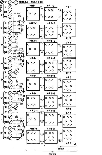
Thermostat heat anticipator settings are indicated for each permitted zone module connection arrangement illustrated in Fig. 11-28.
To Join Modules of the Same Nest Into the Same Zone (i.e., modules no. 1 and 2) Ð Install ®eld-supplied jumpers on thermostat connections (screw terminals) Y to Y and W2 to W2 as shown in Fig. 11. Connect thermostat wires to terminal connections of ®rst module in zone (for consistency). Two-stage cooling may be obtained in this example as shown in Fig. 12 (using a 2-stage thermostat).
To Join Modules Not of the Same Nest Into the Same Zone (i.e., modules no. 2 and 3) Ð Install the factory-supplied jumpers on quick-connect terminals 6 to 1, 7 to 2, and 8 to 3 as shown in Fig. 13. Note that module no. 1 is independently controlled by its own thermostat (in Fig. 13).
|
LEGEND |
AFS |
Ð Air¯ow Switch |
CR |
Ð Control Relay |
ECR |
Ð Economizer Relay |
ECT |
Ð Economizer Outdoor-Air Thermostat |
GV |
Ð Gas Valve (not used on 50ME units) |
HC |
Ð Heater Contactor |
HR |
Ð Heater Relay |
IFC |
Ð Indoor (Evaporator) Fan Contactor |
LLS |
Ð Liquid Line Solenoid |
MC |
Ð Master Cooling |
MCR |
Ð Master Cooling Relay |
MH |
Ð Master Heating |
MHR |
Ð Master Heating Relay |
MU |
Ð Master Unit |
MUR |
Ð Master Unit Relay |
NC |
Ð Normally Closed |
NO |
Ð Normally Open |
NS |
Ð Night Setback |
SW |
Ð Switch |
TRAN Ð Transformer
Quick-Connect Type Terminals (for multiplexing)
Screw-Type Terminals
NOTE: Twelve-zone unit shown. Eight-zone units have modules 1-8 only. Ten-zone units have modules 1-10 only.
Fig. 10 Ð Zone Control Board Component Location
14
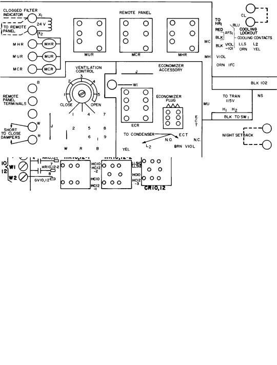
Fig. 10 Ð Zone Control Board Component Location (cont)
15
 Loading...