


48EZ-A
48EZ(N) ---A
Comfortt 13 SEER Single ---Packaged HYBRID HEAT®
Dual Fuel System with Puronr (R ---410A) Refrigerant
Single And Three Phase
2 --- 5 N o m i n a l To n s ( S i z e s 2 4 --- 6 0 )
Installation Instructions
NOTE: Read the entire instruction manual before starting the
installation.
NOTE: Installer: Make sure the Owner’s Manual and Service
Instructions are left with the unit after installation.
TABLE OF CONTENTS
PAGE
SAFETY CONSIDERATIONS 1--2.......................
INTRODUCTION 2...................................
RECEIVING AND INSTALLATION 2--13.................
Check Equipment 2..................................
Identify Unit 2....................................
Inspect Shipment 2.................................
Provide Unit Support 2...............................
Roof Curb 2......................................
Slab Mount 2.....................................
Field Fabricate Ductwork 2............................
Provide Clearances 6.................................
Rig and Place Unit 6.................................
Connect Condensate Drain 7...........................
Install Flue Hood 7...................................
Install Gas Piping 7..................................
Install Duct Connections 11............................
Configuring Units for Downflow (Vertical)
Discharge 11.....................................
Install Electrical Connections 13........................
High--Voltage Connections 13........................
Special Procedures for 208--V Operation 13..............
Control Voltage Connections 13.......................
Balance Point Setting Thermidistat or Hybrid Heat
Thermostat 13....................................
Transformer Protection 13...........................
PRE--START--UP 14...................................
START--UP 15--18.....................................
Check for Refrigerant Leaks 15.........................
Unit Sequence of Operation 15.........................
Start--Up Heating and Make Adjustments 15...............
Checking Heating Control 16.........................
Check Gas Input 16................................
Adjust Gas Input 16................................
Check Burner Flame 17.............................
Start--Up Cooling and Make Adjustments 18...............
Checking Cooling Control Operation 18................
Checking and Adjusting Refrigerant 18.................
Indoor Airflow and Airflow Adjustments 18.............
MAINTENANCE 28--34................................
Air Filter 28........................................
Indoor Blower and Motor 28...........................
Flue Gas Passageways 29..............................
Limit Switch 29.....................................
Burner Ignition 29...................................
Main Burners 29....................................
Outdoor Coil, Indoor Coil, & Condensate Drain Pan 29......
Outdoor Fan 30.....................................
Electrical Controls and Wiring 30.......................
Refrigerant Circuit 30.................................
Gas Input 31........................................
Indoor Airflow 31...................................
Check Defrost Thermostat 31...........................
PuronR Items 31....................................
TROUBLESHOOTING 34..............................
START--UP CHECKLIST 34............................
Installation and servicing of this equipment can be hazardous due
to mechanical and electrical components. Only trained and
qualified personnel should install, repair, or service this equipment.
Untrained personnel can perform basic maintenance functions such
as cleaning and replacing air filters. All other operations must be
performed by trained service personnel. When working on this
equipment, observe precautions in the literature, on tags, and on
labels attached to or shipped with the unit and other safety
precautions that may apply.
Follow all safety codes. Wear safety glasses, protective clothing,
and work gloves. Have fire extinguisher available. Read these
instructions thoroughly and follow all warnings or cautions
included in literature and attached to the unit. Consult local
building codes, the current editions of the National Fuel Gas Code
(NFGC) NFPA 54/ANSI Z223.1, and the National Electrical Code
(NEC) NFPA 70.
In Canada refer to the current editions of the National Standards of
Canada CAN/CSA--B149.1 and .2 Natural Gas and Propane
Installation codes, and Canadian Electrical Code CSA C22.1.
Recognize safety information. This is the safety--alert symbol
When you see this symbol on the unit and in instructions or manuals, be alert to the potential for personal injury. Understand these
signal words: DANGER, WARNING, and CAUTION. These
1
A09034
Fig. 1 -- Unit 48EZ--A
SAFETY CONSIDERATIONS
.
words are used with the safety--alert symbol. DANGER identifies
the most serious hazards which will result in severe personal injury
or death. WARNING signifies hazards which could result in personal injury or death. CAUTION is used to identify unsafe practices which may result in minor personal injury or product and property damage. NOTE is used to highlight suggestions which will
result in enhanced installation, reliability, or operation.
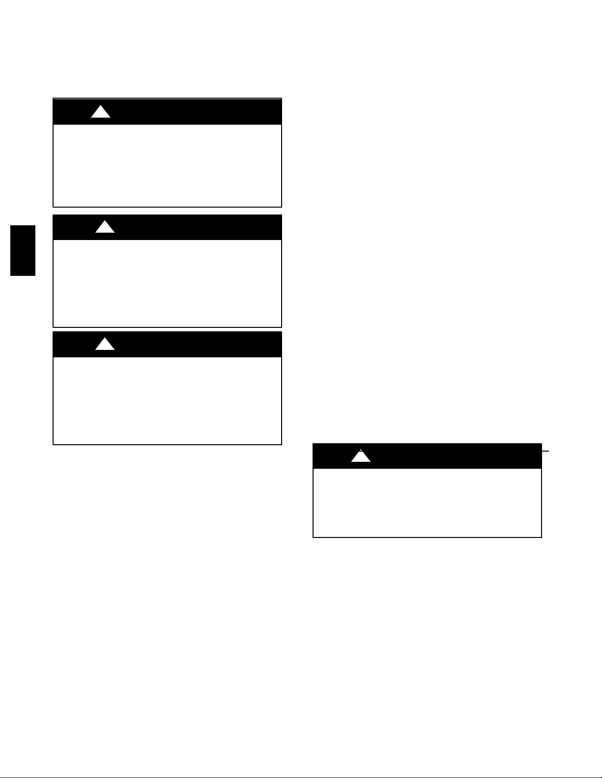
!
WARNING
ELECTRICAL SHOCK HAZARD
Failure to follow this warning could result in personal
injury or death.
Before installing or servicing system, always turn off main
power to system and install lockout tag. There may be
more than one disconnect switch. Turn off accessory heater
power switch if applicable.
!
WARNING
FIRE, EXPLOSION, ELECTRICAL SHOCK AND
48EZ --A
CARBON MONOXIDE POISONING HAZARD
Failure to follow this warning could result in personal
injury, death or property damage.
A qualified installer or agency must use only
factory--authorized kits or accessories when modifying this
product.
!
CAUTION
CUT HAZARD
Failure to follow this caution may result in personal injury.
When removing access panels (see Fig. 19) or performing
maintenance functions inside your unit, be aware of sharp
sheet metal parts and screws. Although special care is taken
to reduce sharp edges to a minimum, be extremely careful
when handling parts or reaching into the unit.
Manufacturer is not responsible for any damage incurred in transit.
Check all items against shipping list. Immediately notify the
nearest equipment distribution office if any item is missing. To
prevent loss or damage, leave all parts in original packages until
installation.
If the unit is to be mounted on a curb in a downflow application,
review Step 9 to determine which method is to be used to remove
the downflow panels before rigging and lifting into place. The
panel removal process may require the unit to be on the ground.
Step 2 — Provide Unit Support
For hurricane tie downs, contact distributor for details and PE
(Professional Engineering) Certificate if required.
ROOF CURB
Install accessory roof curb in accordance with instructions shipped
with curb (See Fig. 4). Install insulation, cant strips, roofing, and
flashing. Ductwork must be attached to curb.
IMPORTANT: The gasketing of the unit to the roof curb is
critical for a water tight seal. Install gasketing material supplied
with the roof curb. Improperly applied gasketing also can result in
air leaks and poor unit performance.
Curb should be level to within 1/4 in. (6 mm). This is necessary for
unit drain to function properly. Refer to accessory roof curb
installation instructions for additional information as required.
Installation on older “G” seriesroof curbs.
Two accessory kits are available to aid in installing a new “G”
series unit on an old “G” roof curb.
1. Accessory kit number CPADCURB001A00, (small chassis)
and accessory kit number CPADCURB002A00, (large
chassis) includes roof curb adapter and gaskets for the
perimeter seal and duct openings. No additional
modifications to the curb are required when using this kit.
2. An alternative to the adapter curb is to modify the existing
curb by removing the outer horizontal flange and use
accessory kit number CPGSKTKIT001A00 which includes
spacer blocks (for easy alignment to existing curb) and
gaskets for the perimeter seal and duct openings. This kit is
used when existing curb is modified by removing outer
horizontal flange.
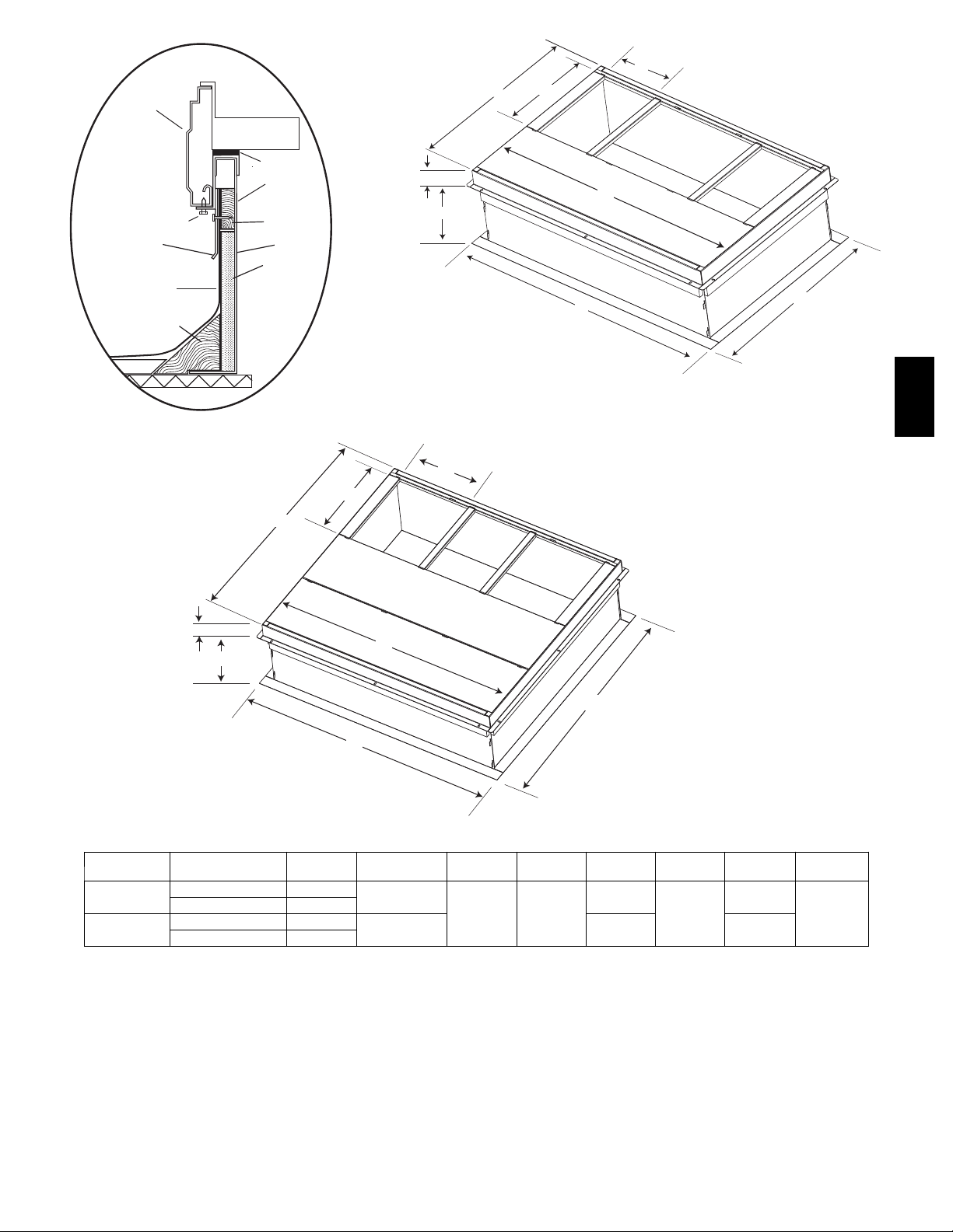
INTRODUCTION
The 48EZ--A unit (see Fig. 1) is a fully self--contained,
combination Category I gas heating/electric heating and cooling
unit designed for outdoor installation (See Fig. 2 and 3 for unit
dimensions). All unit sizes have return and discharge openings for
both horizontal and downflow configurations, and are factory
shipped with all downflow duct openings covered. Units may be
installed either on a rooftop, or on a cement slab (See Fig. 4 for
roof curb dimensions).
Models with an N in the fifth position of the model number are
dedicated Low NOx units designed for California installations.
These models meet the California maximum oxides of nitrogen
(NOx) emissions requirements of 40 nanograms/joule or less as
shipped from the factory and must be installed in California Air
Quality Management Districts or any other regions in North
America where a Low NOx rule exists.
RECEIVING AND INSTALLATION
Step 1 — Check Equipment
IDENTIFY UNIT
The unit model number and serial number are stamped on the unit
information plate. Check this information against shipping papers.
INSPECT SHIPMENT
Inspect for shipping damage before removing packaging materials.
If unit appears to be damaged or is torn loose from its anchorage,
have it examined by transportation inspectors before removal.
Forward claim papers directly to transportation company.
!
UNIT/STRUCTURAL DAMAGE HAZARD
Failure to follow this caution may result in property damage.
Ensure there issufficient clearance for saw blade when cutting
the outer horizontal flange of the roof curb so there is no
damage to the roof or flashing.
SLAB MOUNT
Place the unit on a solid, level concrete pad that is a minimum of 4
in. (102 mm) thick with 2 in. (51 mm) above grade. The slab
should be flush on the compressor end of the unit (to allow
condensate drain installation) and should extend 2 in. (51 mm) on
the three remaining sides of the unit. Do not secure the unit to the
slab except when required by local codes.
CAUTION
Step 3 — Field Fabricate Ductwork
Secure all ducts to roof curb and building structure on vertical
discharge units. Do not connect ductwork to unit. For horizontal
applications, unit is provided with flanges on the horizontal
openings. All ductwork should be secured to the flanges. Insulate
and weatherproof all external ductwork, joints, and roof openings
with counter flashing and mastic in accordance with applicable
codes.
2
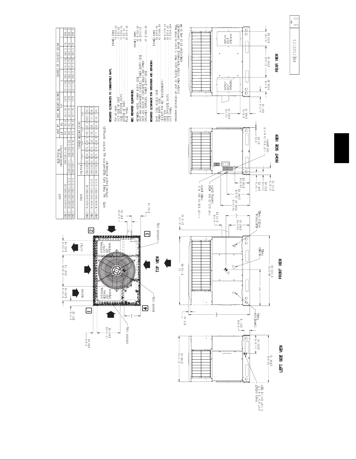
48EZ --A
Fig. 2 -- 48EZ--A24--36 Unit Dimensions
3
A09450
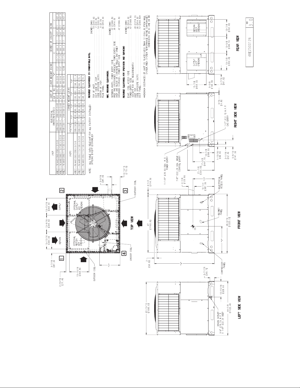
48EZ --A
Fig. 3 -- 48EZ--A42--60 Unit Dimensions
4
A09451
HVAC unit
base rails
Anchor screw
Flashing field
supplied
Roofing material
field supplied
Cant strip
field supplied
HVAC unit
basepan
Sealing
Gasket
Roofcurb
Wood nailer*
Roofcurb*
Insulation
(field supplied)
B
G
C
H
F
A
D
E
*Provided with roofcurb
ROOF CURB DETAIL
A
F
SMALL CURB
A09090
A09418
48EZ --A
B
C
G
H
E
D
LARGE CURB
UNIT SIZE
Small
Large
NOTES:
1. Roof curb must be set up for unit being installed.
2. Seal strip must be applied, as required, to unit being installed.
3. Roof curb is made of 16--gauge steel.
4. Attach ductwork to curb (flanges of duct rest on curb).
5. Insulated panels: 1--in. (25.4 mm) thick fiberglass 1 lb. density.
CATALOG
NUMBER
CPRFCURB010A00 11 (279)
CPRFCURB011A00 14 (356)
CPRFCURB012A00 11 (279)
CPRFCURB013A00 14 (356)
IMPORTANT: Do not install large base pan HYBRID HEAT
units onto the small base pan (common curb). The center of gravity
on a large base pan HYBRID HEAT unit could overhang the curb
causing an unsafe condition. Before installing any large base pan
unit onto the common curb, check the “Y” distance in the product
A
IN. (mm)BIN. (mm)*
10 (254)
14 (356)
Fig. 4 -- Roof Curb Dimensions
A09415
A09419
C
IN. (mm)DIN. (mm)EIN. (mm)FIN. (mm)GIN. (mm)HIN. (mm)
16 (406)
47.8
(1214)
32.4 (822)
43.9
(1116)
2.7 (69)
30.6 (778)
46.1 (1170)
42.2 (1072)
literature dimensional drawing to ensure that “Y” is greater than 14
in. (356 mm). Do not install any large base pan unit onto the
common curb with a “Y” dimension (center of gravity) less than 14
in. (356 mm).
5
CAUTION - NOTICE TO RIGGERS
PRUDENCE - AVIS AUX MANIPULATEUR
PANNEAUX D'ACCES DOIT ÊTRE EN PLACE POUR MANIPULATION.
Use top skid as spreader bar. / Utiliser la palette du haut comme barre de répartition
ACCESS PANELS MUST BE IN PLACE WHEN RIGGING.
DUCTS
MINIMUM HEIGHT: 36" (914.4 mm)
HAUTEUR MINIMUM
48EZ --A
SEE DETAIL A
VOIR DÉTAIL A
RIGGING WEIGHTS (SMALL CABINET) RIGGING WEIGHTS (LARGE CABINET)
Unit
Rigging
Weight
*For 460 Volt units add 14 lb (6.35 kg) to the rigging weight.
NOTE: See dimensional drawing for corner weights.
24 30 36
lb kg lb kg lb kg lb kg lb kg lb kg
359 163 373 169 379 172
Ducts passing through an unconditioned space must be insulated
and covered with a vapor barrier.
If a plenum return is used on a vertical unit, the return should be
ducted through the roof deck to comply with applicable fire codes.
See unit rating plate for any required clearances around ductwork.
Cabinet return--air static shall not exceed --.25 IN. W.C.
Step 4 — Provide Clearances
The required minimum operating and service clearances are shown
in Fig. 2 and 3.
IMPORTANT: Do not restrict outdoor airflow. An air restriction
at either the outdoor--air inlet or the fan discharge may be
detrimental to compressor life.
The condenser fan pulls air through the condenser coil and
discharges it through the top grille. Be sure that the fan discharge
does not recirculate to the condenser coil. Do not locate the unit in
either a corner or under an overhead obstruction. The minimum
clearance under a partial overhang (such as a normal house
overhang) is 48--in. (1219 mm) above the unit top. The maximum
horizontal extension of a partial overhang must not exceed 48--in.
(1219 mm).
Do not place the unit where water, ice, or snow from an overhang
or roof will damage or flood the unit. Do not install the unit on
carpeting or other combustible materials. The unit may be installed
on Class A, B, or C roof covering materials. Slab mounted units
should be at least 4--in. (102 mm) above thehighest expected water
and runoff levels. Do not use unit if it has been under water.
UNIT HEIGHT
HAUTEUR D'UNITÉ
DETAIL A
VOIR DÉTAIL A
Unit
Rigging
Weight
42 48 60
461 209 482 219 507 230
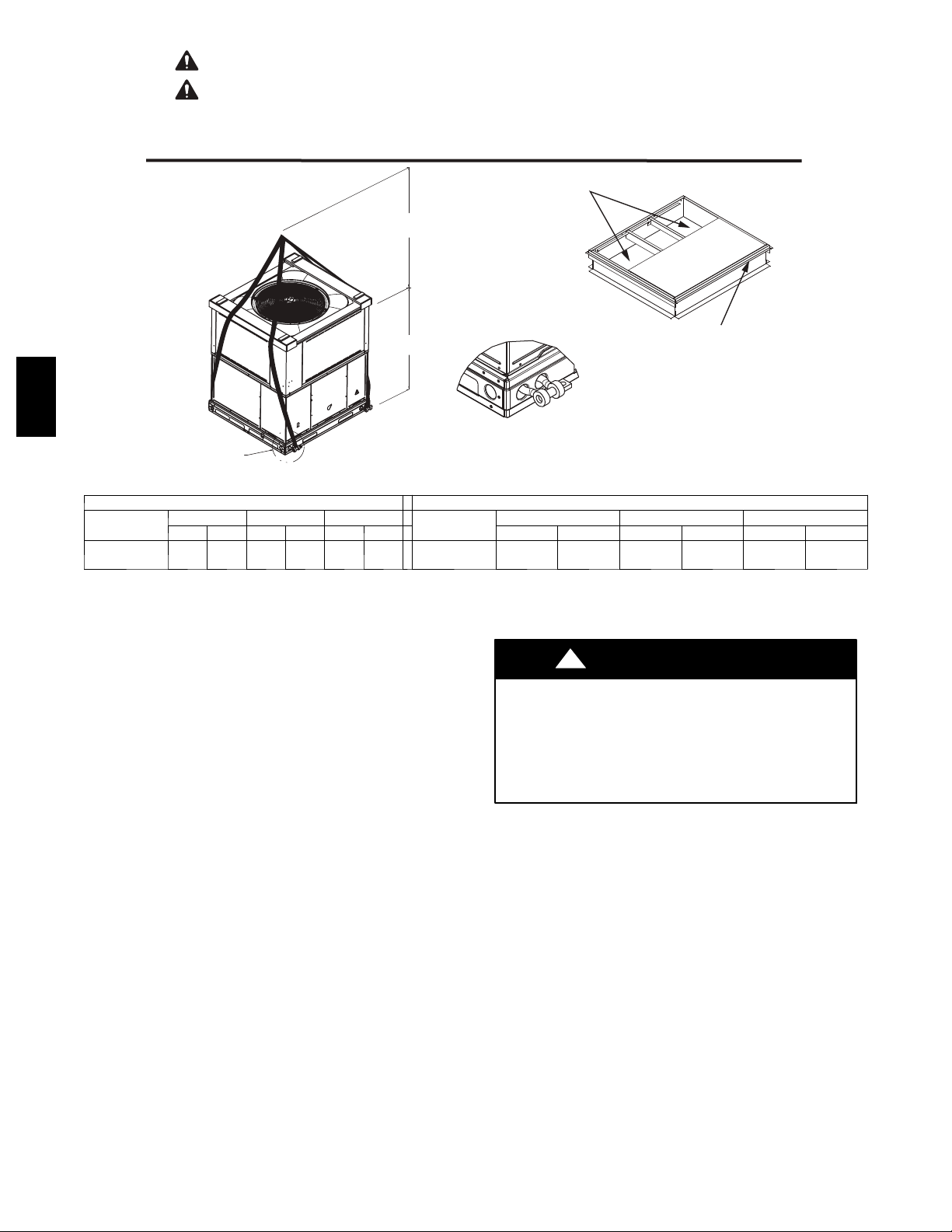
Fig. 5 -- 48EZ--A Suggested Rigging
Step 5 — Rig and Place Unit
!
PERSONAL INJURY OR PROPERTY DAMAGE
HAZARD
Failure to follow this warning could result in personal
injury, death or property damage.
When installing the unit on a rooftop, be sure the roof will
support the additional weight.
Rigging and handling of this equipment can be hazardous for
many reasons due to the installation location (roofs, elevated
structures, etc.).
Only trained, qualified crane operators and ground support staff
should handle and install this equipment.
When working with this equipment, observe precautions in the
literature, on tags, stickers, and labels attached to the equipment,
and any other safety precautions that might apply.
Training for operators of the lifting equipment should include, but
not be limited to, the following:
1. Application of the lifter to the load, and adjustment of the
lifts to adapt to various sizes or kinds of loads.
2. Instruction in any special operation or precaution.
3. Condition of the load as it relates to operation of the lifting
kit, such as balance, temperature, etc.
Follow all applicable safety codes. Wear safety shoes and work
gloves.
SEAL STRIP MUST BE IN
PLACE BEFORE PLACING
UNIT ON ROOF CURB
BANDE SCELLANT DOIT ÊTRE
EN PLACE AVANT DE PLACER
L'UNITÉ SUR LA BASE DE TOIT
50CY502286 2.0
WARNING
A09051
6
Inspection
Prior to initial use, and at monthly intervals, all rigging shackles,
clevis pins, and straps should be visually inspected for any
damage, evidence of wear, structural deformation, or cracks.
Particular attention should be paid to excessive wear at hoist
hooking points and load support areas. Materials showing any kind
of wear in these areas must not be used and should be discarded.
!
WARNING
UNIT FALLING HAZARD
Failure to follow this warning could result in personal
injury or death.
Never stand beneath rigged units or lift over people.
!
WARNING
PROPERTY DAMAGE HAZARD
Failure to follow this warning could result in personal
injury/death or property damage.
When straps are taut, the clevis should be a minimum of 36
in. (914 mm) above the unit top cover.
Rigging/Lifting of Unit (See Fig. 5)
Lifting holes are provided in base rails as shown in Fig. 2 and 3.
1. Leave top shipping skid on the unit for use as a spreaderbar
to prevent the rigging straps from damaging the unit. If the
skid is not available, use a spreader bar of sufficient length
to protect the unit from damage.
2. Attach shackles, clevis pins, and straps to the base rails of
the unit. Be sure materials are rated to hold the weight of the
unit (See Fig. 5).
3. Attach a clevis of sufficient strength in the middle of the
straps. Adjust the clevis location to ensure unit is lifted level
with the ground.
After the unit is placed on the roof curb or mounting pad, remove
the top skid.
Step 6 — Connect Condensate Drain
NOTE: When installing condensate drain connection be sure to
comply with local codes and restrictions.
Model 48EZ--A disposes of condensate water through a 3/4 in.
NPT fitting which exits through the compressor access panel (See
Fig. 2 and 3 for location).
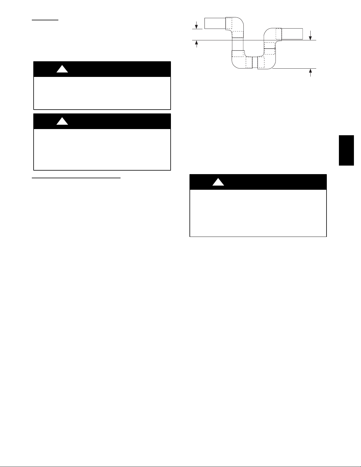
Condensate water can be drained directly onto the roof in rooftop
installations (where permitted) or onto a gravel apron in ground
level installations. Install a field--supplied condensate trap at end
of condensateconnection to ensure proper drainage. Make sure that
the outlet of the trap is at least 1 in. (25 mm) lower than the
drain--pan condensate connection to prevent the pan from
overflowing (See Fig. 6). Prime the trap with water. When using a
gravel apron, make sure it slopes away from the unit.
If the installation requires draining the condensate water away
from the unit, install a 2--in. (51 mm) trap at the condensate
connection to ensure proper drainage (See Fig. 6). Make sure that
the outlet of the trap is at least 1 in. (25 mm) lower than the
drain--pan condensate connection. This prevents the pan from
overflowing.
Prime the trap with water. Connect a drain tube -- using a minimum
of 3/4--in. PVC or 3/4--in. copper pipe (all field--supplied) -- at the
outlet end of the 2--in. (51 mm) trap. Do not undersize the tube.
Pitch the drain tube downward at a slope of at least 1--in. (25 mm)
for every 10 ft (3 m) of horizontal run. Be sure to check the drain
tube for leaks.
TRAP
OUTLET
1-in. (25 mm) min.
2-in. (51 mm) min.
A09052
Fig. 6 -- Condensate Trap
Step 7 — Install Flue Hood
The flue assembly is secured and shipped in the return air duct.
Remove duct cover to locate the assembly (See Fig. 8 and 9).
NOTE: Dedicated low NOx models MUST be installed in
California Air Quality Management Districts where a Low NOx
rule exists.
These models meet the California maximum oxides of nitrogen
(NOx) emissions requirements of 40 nanograms/joule or less as
shipped from the factory.
NOTE: Low NOx requirements apply only to natural gas
installations.
!
WARNING
CARBON MONOXIDE POISONING HAZARD
Failure to follow this warning could result in personal
injury or death.
The venting system is designed to ensure proper venting.
The flue hood assembly must be installed as indicted in this
section of the unit installation instructions.
Install the flue hood as follows:
1. This installation must conform with local building codes
and with the National Fuel Gas Code (NFGC) NFPA 54 /
ANSI Z223.1, (in Canada, CAN/CGA B149.1, and
B149.2) latest revision. Refer to Provincial and local
plumbing or wastewater codes and other applicable local
codes.
2. Remove flue hood from shipping location (inside the return
section of the blower compartment--see Fig. 8 & 9). Remove the return duct cover to locate the flue hood. Place
flue hood assembly over flue panel. Orient screw holes in
flue hood with holes in the flue panel.
3. Secure flue hood to flue panel by inserting a single screw on
the top flange and the bottom flange of the hood.
Step 8 — Install Gas Piping
The gas supply pipe enters the unit through the access hole
provided. The gas connection to the unit is made to the 1/2--in.
(12.7 mm) FPT gas inlet on the gas valve.
Install a gas supply line that runs to the heating section. Refer to
Table 2 and the NFGC for gas pipe sizing. Do not use cast--iron
pipe. It is recommended that a black iron pipe is used. Check the
local utility for recommendations concerning existing lines. Size
gas supply piping for 0.5 IN. W.C. maximum pressure drop. Never
use pipe smaller than the 1/2--in. (12.7 mm) FPT gas inlet on the
unit gas valve.
For natural gas applications, the gas pressure at unit gas connection
must not be less than 4.0 IN. W.C. or greater than 13 IN. W.C.
while the unit is operating. For propane applications, the gas
pressure must not be less than 11.0 IN. W.C. or greater than 13 IN.
W.C. at the unit connection.
48EZ --A
7
A 1/8--in. (3.2 mm) NPT plugged tapping, accessible for test gauge
connection, must be installed immediately upstream of the gas
supply connection to the gas valve.
When installing the gas supply line, observe local codes pertaining
to gas pipe installations. Refer to the NFGC NFPA 54/ANSI
Z223.1 latest edition (in Canada, CAN/CGA B149.1).
NOTE: In the state of Massachusetts:
1. Gas supply connections MUST be performed by a licensed
plumber or gas fitter.
2. When flexible connectors are used, the maximum length
shall not exceed 36 in. (915 mm).
3. When lever handle type manual equipment shutoff valves
are used, they shall be T--handle valves.
4. The use of copper tubing for gas piping is NOT approved
by the state of Massachusetts.
In the absence of local building codes, adhere to the following
pertinent recommendations:
1. Avoid low spots in long runs of pipe. Grade all pipe 1/4 in.
(6.35 mm) for every 15 ft (4.6 m) of length to prevent traps.
Grade all horizontal runs downward to risers. Use risers to
connect to heating section and to meter.
48EZ --A
2. Protect all segments of piping system against physical and
thermal damage. Support all piping with appropriate straps,
hangers, etc. Use a minimum of one hanger every 6 ft (1.8
m). For pipe sizes larger than 1/2 in., (12.7 mm) follow
recommendations of national codes.
3. Apply joint compound (pipe dope) sparingly and only to
male threads of joint when making pipe connections. Use
only pipe dope that is resistant to action of liquefied
petroleum gases as specified by local and/or national codes.
Never use Teflon tape.
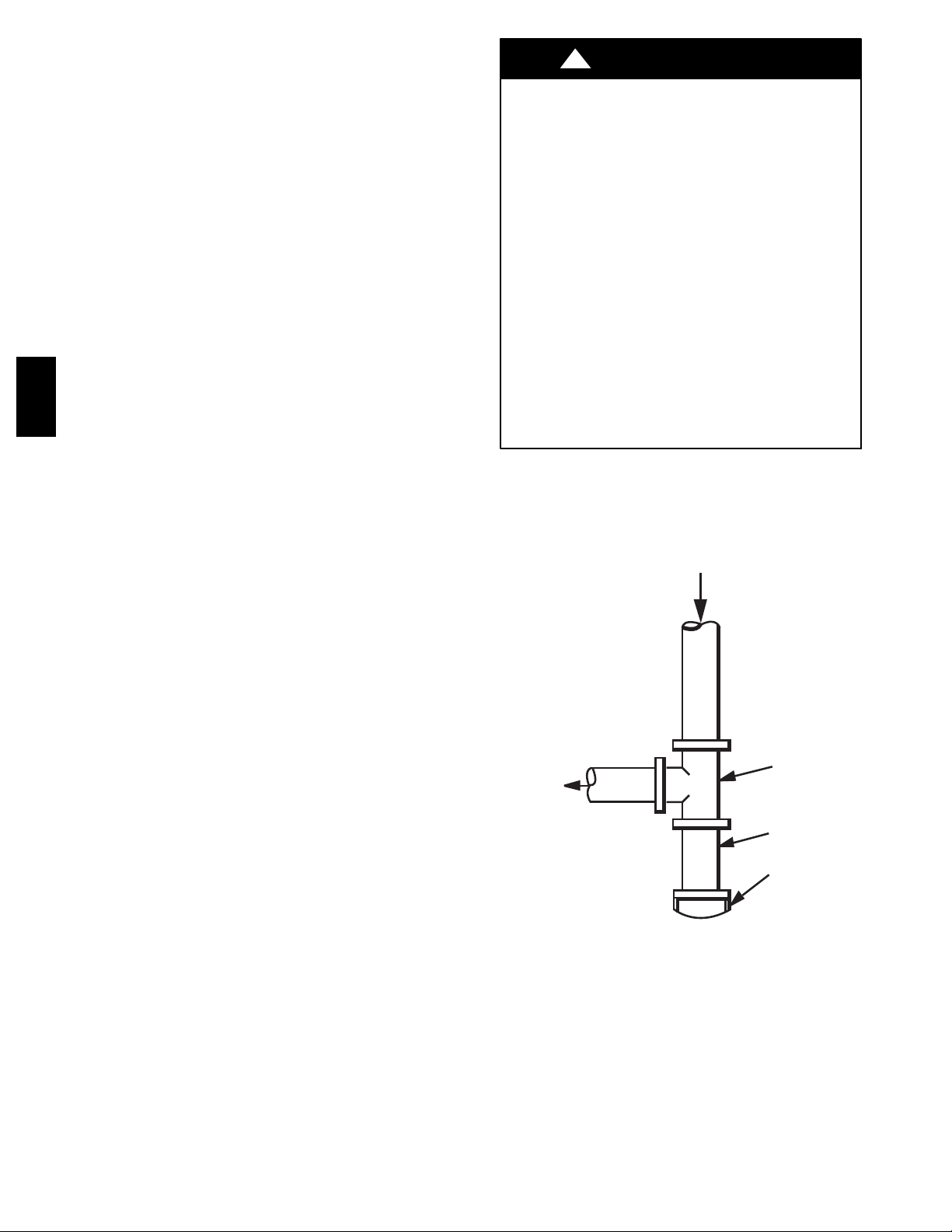
4. Install sediment trap in riser leading to heating section (See
Fig. 7). This drip leg functions as a trap for dirt and
condensate.
5. Install an accessible, external, manual main shutoff valve in
gas supply pipe within 6 ft (1.8 m) of heating section.
6. Install ground--joint union close to heating section between
unit manual shutoff and external manual main shut--off
valve.
7. Pressure test all gas piping in accordance with local and
national plumbing and gas codes before connecting piping
to unit.
NOTE: Pressure test the gas supply system after the gas supply
piping is connected to the gas valve. The supply piping must be
disconnected from the gas valve during the testing of the piping
systems when test pressure is in excess of 0.5 psig. Pressure test the
gas supply piping system at pressures equal to or less than 0.5 psig.
The unit heating section must be isolated from the gas piping
system by closing the external main manual shutoff valve and
slightly opening the ground--joint union.
!
WARNING
FIRE OR EXPLOSION HAZARD
Failure to follow this warning could result in personal injury,
death and/or property damage.
--Connect gas pipe to unit using a backup wrench to avoid
damaging gas controls.
--Never purge a gas line into a combustion chamber. Never
test for gas leaks with an open flame. Use a commercially
available soap solution made specifically for the detection of
leaks to check all connections.
--Use proper length of pipe to avoid stress on gas control
manifold.
--If a flexible connector is required or allowed by authority
having jurisdiction, black iron pipe shall be installed at
furnace gas valve and extend a minimum of 2 in. (51 mm)
outside furnace casing.
--If codes allow a flexible connector, always use a new
connector. Do not use a connector which has previously
serviced another gas appliance.
8. Check for gas leaks at the field--installed and
factory--installed gas lines after all piping connections have
been completed. Use a commercially available soap solution
made specifically for the detection of leaks (or method
specified by local codes and/or regulations).
IN
TEE
OUT
NIPPLE
CAP
C99020
Fig. 7 -- Sediment Trap
8
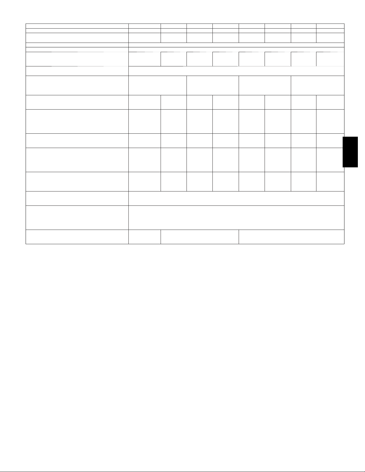
Table 1 – Physical Data -- Unit 48EZ--A
UNIT SIZE 48EZ ---A 24040 24060 30040 30060 36060 36090 42060 42090
NOMINAL C APACITY --- ton 2 2 2 --- 1 / 2 2 --- 1 / 2 3 3 3 --- 1 / 2 3 --- 1 / 2
SHIPPING WEIGHT ---lb.
COMPRESSORS Scroll
Quantity 1
REFRIGERANT (R --- 410A)
Quantity --- lb
REFRIGERANT METERING
Nominal Cooling Airflow---(CFM)
Natural Gas Qty...Drill Size (Factory Installed)
Propane GasQty...Drill Size
HIGH --- PRESSURE SWITCH
LOW---PRESSURE SWITCH
RETURN--- AIR FILTERS † }
*Based on altitude of 0 to 2000 ft (0 ---610 m).
{Required filter sizes shown are based on the larger of the ARI (Air Conditioning and Refrigeration Institute) rated cooling airflow or the heating airflow velocity of
300 ft/minute for high ---capacity type. Air filter pressure drop for non ---standard filters must not exceed 0.08 IN. W.C.
} If using accessory filter rack refer to filter rack installation instructions for correct filter size and quantity.
DEVICE
OUTDOOR ORIFICE
in. (qty)
(mm)
OUTDOOR COIL
Rows...Fins/in.
F a c e A r e a --- s q f t
OUTDOOR FAN
Nominal Cfm
Diameter--- in.
Motor Hp (Rpm)
INDOOR COIL
Rows...Fins/in.
F a c e A r e a --- s q f t
INDOOR BLOWER
S i z e --- i n .
M o t o r --- h p
FURNACE SECTION*
Burner Orifice
( p s i g ) C u t --- o u t
Reset (Auto)
L O S S --- O F --- C H A R G E /
(Liquid Line) (psig)
C u t --- o u t
Reset (auto)
Throwaway (in.)
(kg)
(kg)
(mm)
(mm)
(mm)
359
163
8.3
3.8
0.032 (2)
2...21
11.9
2000
24
610
1/5 (810)
3...17
3.7
800
10x10
254x254
1/2
2...44
2...55
20x20x1
508x508x25
.81
359
163
8.3
3.8
2...21
11.9
2000
24
610
1/5 (810)
3...17
3.7
800
10x10
254x254
1/2
2...38
2...53
373
169
10.2
4.6
0.035 (2)
2...21
11.9
2700
24
610
1/5 (810)
3...17
3.7
1000
10x10
254x254
1/2
2...44
2...55
20x24x1
508x610x25
373
169
10.2
4.6
I n do o r --- T X V, O u t door --- A cc u r a t e r
.89
2...21
11.9
2700
24
610
1/5 (810)
3...17
3.7
1000
10x10
254x254
1/2
2...38
2...53
650 +/---15
420 +/---25
2 0 + / --- 5
45 +/---10
379
172
7.9
3.6
2...21
11.9
2700
24
610
1/5 (810)
3...17
3.7
1200
11x10
279x254
3/4
2...38
2...53
0.037 (2)
.94
379
172
7.9
3.6
2...21
11.9
2700
24
610
1/5 (810)
3...17
3.7
1200
11x10
279x254
3/4
3...38
3...53
610x762x25
24x30x1
461
209
10.0
4.5
0.038 (Left)
0.040(Right)
2...21
13.6
3100
26
660
1/5 (810)
3...17
4.7
1400
11x10
279x254
3/4
2...38
2...53
.97/1.02
1/5 (810)
279x254
461
209
10.0
4.5
2...21
13.6
3100
26
660
3...17
4.7
1400
11x10
3/4
3...38
3...53
48EZ --A
9
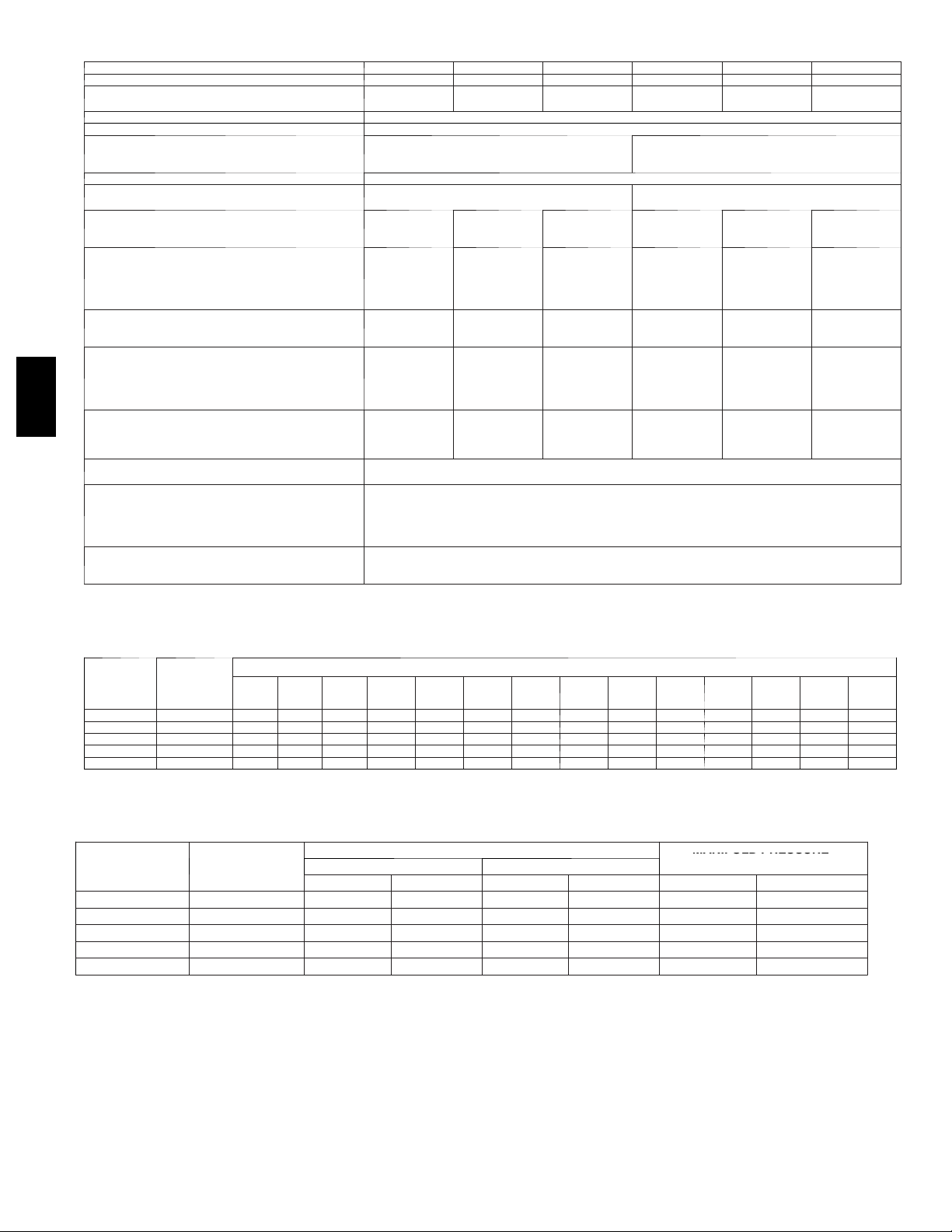
Table 1 -- Physical Data -- Unit 48EZ--A (Cont’d)
NUMBER
OF
MANIFOLD
PRES
SURE
ORIFICES
UNIT SIZE 48EZ ---A 48090 48115 48130 60090 60115 60130
NOMINAL C APACITY --- ton 4 4 4 5 5 5
OPERATING WEIGHT --- lb
COMPRESSORS Scroll
Quantity 1
REFRIGERANT (R --- 410A)
Quantity --- lb
REFRIGERANT METERING DEVICE TXV
OUTDOOR ORIFICE ---in. (qty)
OUTDOOR COIL
Rows...Fins --- in.
F a c e A r e a --- s q f t
OUTDOOR FAN
Nominal Cfm
Diameter--- in.
M o t o r H p --- R p m
INDOOR COIL
Rows...Fins --- in.
F a c e A r e a --- s q f t
INDOOR BLOWER
Nominal Cooling Airflow---(CFM)
48EZ --A
Natural Gas Qty...Drill Size (Factory Installed)
*Based on altitude of 0 to 2000 ft (0 ---610 m).
{Required filter sizes shown are based on the larger of the ARI (Air Conditioning and Refrigeration Institute) rated cooling airflow or the heating airflow velocity of
300 ft/minute for high ---capacity type. Air filter pressure drop for non ---standard filters must not exceed 0.08 IN. W.C.
} If using accessory filter rack refer to filter rack installation instructions for correct filter size and quantity.
Propane GasQty...Drill Size
HIGH --- PRESSURE SWITCH (psig) Cut --- out
LOW---PRESSURE SWITCH
S i z e --- i n .
M o t o r --- h p
FURNACE SECTION*
Burner Orifice
Reset (Auto)
L O S S --- O F --- C H A R G E /
(Liquid Line) (psig)
C u t --- o u t
Reset (auto)
RETURN--- AIR FILTERS †
Throwaway (in.)
(mm)
(kg)
(kg )
(mm)
(mm)
(mm)
482
219
2...21
13.6
3100
26
660
1/5 (810)
3...17
4.7
1600
11x10
279x254
1.0
3...38
3...53
482
219
9.6
4.4
0.046 (2)
1.2
2...21
13.6
3100
26
660
1/5 (810)
3...17
4.7
1600
11x10
279x254
1.0
3...33
3...51
482
219
2...21
13.6
3100
26
660
1/5 (810)
3...17
4.7
1600
11x10
279x254
1.0
3...31
3...49
650 +/---15
420 +/---25
2 0 + / --- 5
45 +/---10
24x36x1
(610x914x25)
507
230
2...21
17.5
3500
26
660
1/5 (810)
3...17
5.7
1850
11x10
279x254
1.0
3...38
3...53
507
230
12.3
5.6
0.052 (2)
1.3
2...21
17.5
3500
26
660
1/5 (810)
3...17
5.7
1850
11x10
279x254
1.0
3...33
3...51
Table 2 – Maximum Gas Flow Capacity*
NOMINAL
IRON
PIPE,
SIZE (IN.)
1/2 .622 175 120 97 82 73 66 61 57 53 50 44 40 — —
3/4 .824 360 250 200 170 151 138 125 118 110 103 93 84 77 72
1 1.049 680 465 375 320 285 260 240 220 205 195 175 160 145 135
1 --- 1 / 4 1.380 1400 950 770 600 580 530 490 460 430 400 360 325 300 280
1 --- 1 / 2 1.610 2100 1460 1180 990 900 810 750 690 650 620 550 500 460 430
* Capacity of pipe in cu ft of gas per hr for gas pressure of 0.5 psig or less. Pressure drop of 0.5---IN. W.C. (based on a 0.60 specific gravity gas). Refer toTable2
and National Fire Protection Association NFPA 54/ANSI Z223.1.
† This length includes an ordinary number of fittings.
INTERNAL
DIAMETER
(IN.)
10
(3.1)20(6.1)30(9.1)40(12.2)50(15.2)60(18.3)70(21.3)80(24.4)90(27.4)
LENGTH OF PIPE, FT† (m)
100
(30.5)
125
(38.1)
(46.0)
150
175
(53.3)
507
230
2...21
17.5
3500
26
660
1/5 (810)
3...17
5.7
1850
11x10
279x254
1.0
3...31
3...49
200
(61.0)
Table 3 – Heating Inputs
HEATING INPUT
(BTUH)
GAS SUPPL Y PRESSURE (IN. W.C.)
Natural{ Propane*{
Min Max Min Max Natural{ Propane*†
40,000 2 4.0 13.0 11.0 13.0 3.2∼3.8 10.0∼11.0
60,000 2 4.0 13.0 11.0 13.0 3.2∼3.8 10.0∼11.0
90,000 3 4.0 13.0 11.0 13.0 3.2∼3.8 10.0∼11.0
115,000 3 4.0 13.0 11.0 13.0 3.2∼3.8 10.0∼11.0
130,000 3 4.0 13.0 11.0 13.0 3.2∼3.8 10.0∼11.0
*When a unit is converted to propane, different size or ifices must be used. See separate, natural --- to ---propane conversion kit instructions.
{Based on altitudes from sea level to 2000 ft (610 m) above sea level. In U.S.A. for al titudes above 2000 ft (610 m), reduce input rating 4 percent for each addi-
tional 1000 ft (305 m) above sea level. In Canada, from 2000 ft (610 m) above sea level to 4500 ft (1372 m) above sea level, dera te the unit 10 percent.
MANIFOLD PRESSURE
(IN. W.C.)
10
Step 9 — Install Duct Connections
The unit has duct flanges on the supply-- and return--air openings
on the side and bottom of the unit. For downshot applications, the
ductwork connects to the roof curb (See Fig. 2 and 3 for
connection sizes and locations).
Configuring Units for Downflow (Vertical) Discharge
!
ELECTRICAL SHOCK HAZARD
Failure to follow this warning could result in personal injury
or death.
Before installing or servicing system, always turn off main
power to system and install lockout tag. There may bemore
than one disconnect switch.
1. Open all electrical disconnects before starting any service
work.
2. Remove horizontal (metal) duct covers to access vertical
(downflow) discharge duct knockouts in unit basepan. (See
Fig. 8.)
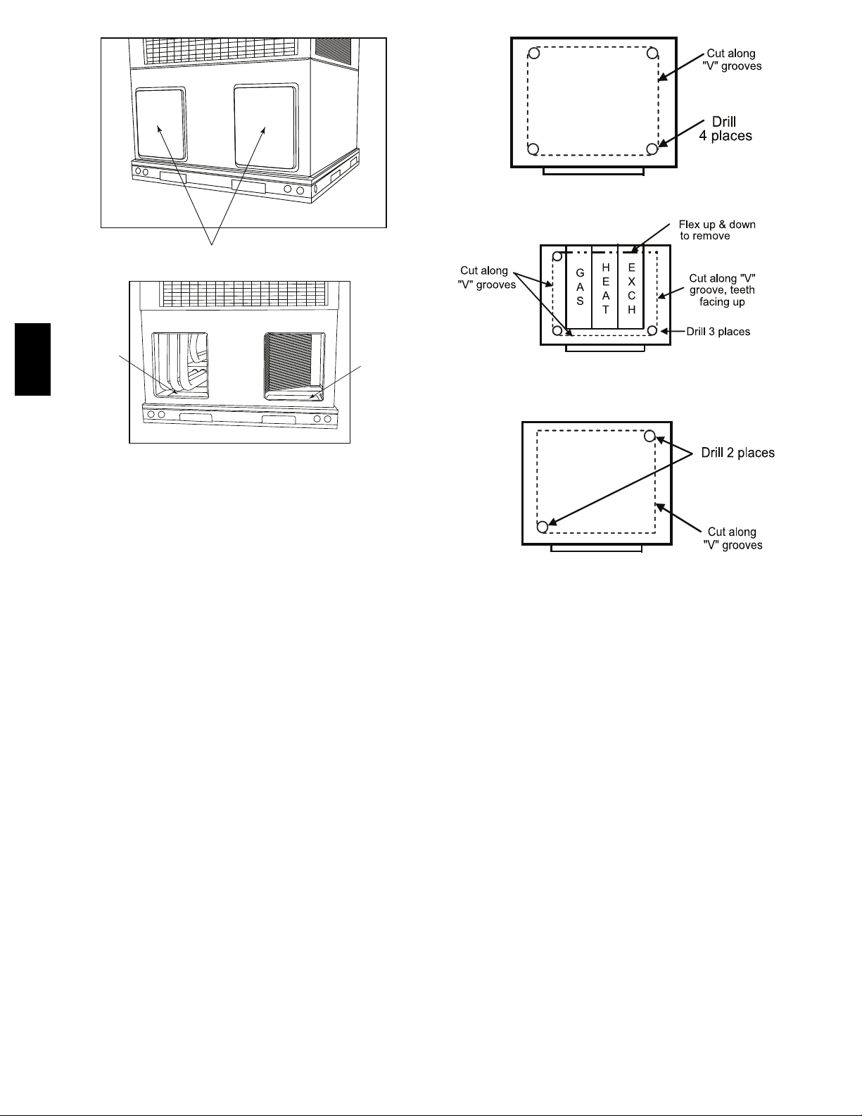
3. Using Fig. 9 as a guide, proceed to cut out the downflow
duct panels.
4. Drill 1/2 in. (13 mm) diameter or larger holes in all four
corners of duct panels.
NOTE: On large chassis units remove sheet metal shields on
panels by using a screw driver to shear off retainers and discard.
5. On left and side supply duct opening side with keyhole or
single bladed hacksaw cut out panel along “V” groove.
6. On right side, with keyhole or single blade hacksaw, with
teeth facing up and starting from the front and moving to
the rear, cut along “V” groove.
7. Now with three sides cut, flex panel up and down to re-
move.
8. Replace side access panel and duct cover.
9. After completing unit conversion, perform all safety checks
and power up unit.
Alternate Method
1. Open all electrical disconnects and install lockout tag before
starting any service work.
2. Remove horizontal (metal) ductcovers to access vertical
(downflow) discharge duct knockouts in unit basepan. (See
Fig. 8.)
3. Leave top shipping crate on unit during this method.
4. Tip unit over on the front side (access panels) so the bottom
of the base pan is accessible.
5. Drill two holes diagonally opposed, of suitable size to ac-
commodate jigsaw or reciprocating saw. (See Fig. 9.)
NOTE: On large chassis units remove sheet metal shields on
panels by using a screw driver to shear off retainers and discard.
WARNING
!
CAUTION
PROPERTY DAMAGE HAZARD
Failure to follow this caution may result in property damage.
Collect ALL screws that were removed. Do not leave screws
on rooftop as permanent damage to the roof may occur.
6. Using a suitable saw cut along “V” groove and remove duct
panels.
7. Tip unit back onto its base and replace duct covers.
8. After completing unit conversion, perform all safety checks
and power up unit.
NOTE: The design and installation of the duct system must be in
accordance with the standards of the NFPA for installation of
nonresidence--type air conditioning and ventilating systems, NFPA
90A or residence--type, NFPA 90B; and/or local codes and
ordinances.
Adhere to the following criteria when selecting, sizing, and
installing the duct system:
1. Units are shipped for horizontal duct installation (by
removing duct covers).
2. Select and size ductwork, supply--air registers, and
return--air grilles according to American Society of Heating,
Refrigeration and Air Conditioning Engineers (ASHRAE)
recommendations.
3. Use flexible transition between rigid ductwork and unit to
prevent transmission of vibration. The transition may be
screwed or bolted to duct flanges. Use suitable gaskets to
ensure weather tight and airtight seal.
4. All units must have field--supplied filters or accessory filter
rack installed in the return--air side of the unit.
Recommended sizes for filters are shown in Table 1.
5. Size all ductwork for maximum required airflow (either
heating or cooling) for unit being installed. Avoid abrupt
duct size increases or decreases or performance may be
affected.
6. Adequately insulate and weatherproof all ductwork located
outdoors. Insulate ducts passing through unconditioned
space, and use vapor barrier in accordance with latest issue
of Sheet Metal and Air Conditioning Contractors National
Association (SMACNA) and Air Conditioning Contractors
of America (ACCA) minimum installation standards for
heating and air conditioning systems. Secure all ducts to
building structure.
7. Flash, weatherproof, and vibration--isolate all openings in
building structure in accordance with local codes and good
building practices.
48EZ --A
!
UNIT COMPONENT DAMAGE HAZARD
Failure to follow this caution may result in damage to the
unit being installed.
When cutting duct panels, do not contact or damage any
internal components (heat exchanger, electric heat). Do not
use a saw blade that protrudes more than 1 in. (25 mm) into
unit.
CAUTION
11
Return Duct Panels
Horizontal Duct Covers
A09061
Basepan
Downflow
(Vertical)
Supply
Knockout
48EZ --A
Basepan
Downflow
(Vertical)
Return
Knockout
A09060
Supply Duct Panels
Fig. 8 -- Supply and Return Duct Opening
Return & Supply Duct Panels from
Underside of Base (Alternate Method)
A09420
Fig. 9 -- Vertical (Downflow) Discharge Duct Knockouts
12
 Loading...